Page 1343 of 2389

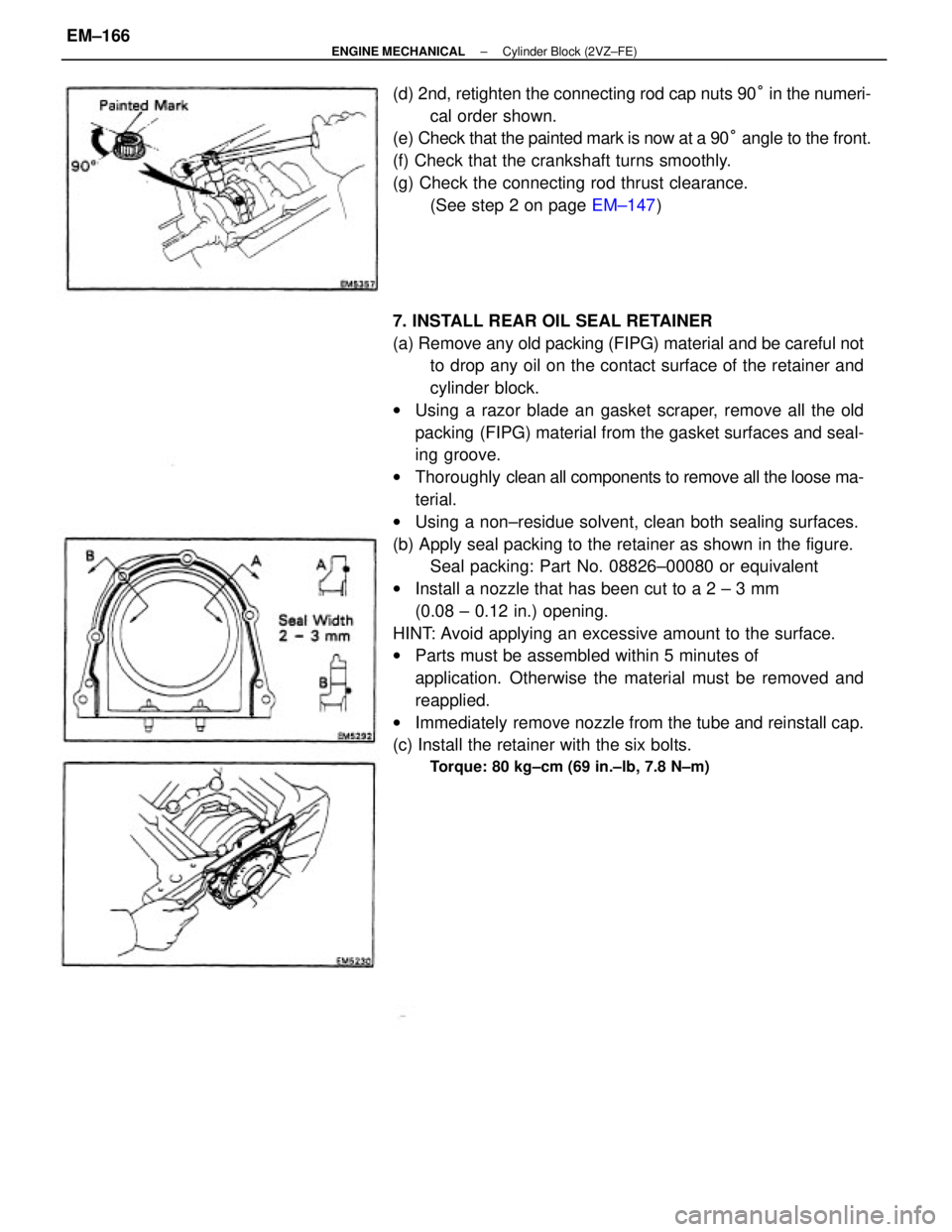
7. INSTALL REAR OIL SEAL RETAINER
(a) Remove any old packing (FIPG) material and be careful not
to drop any oil on the contact surface of the retainer and
cylinder block.
wUsing a razor blade an gasket scraper, remove all the old
packing (FIPG) material from the gasket surfaces and seal-
ing groove.
wThoroughly clean all components to remove all the loose ma-
terial.
wUsing a non±residue solvent, clean both sealing surfaces.
(b) Apply seal packing to the retainer as shown in the figure.
Seal packing: Part No. 08826±00080 or equivalent
wInstall a nozzle that has been cut to a 2 ± 3 mm
(0.08 ± 0.12 in.) opening.
HINT: Avoid applying an excessive amount to the surface.
wParts must be assembled within 5 minutes of
application. Otherwise the material must be removed and
reapplied.
wImmediately remove nozzle from the tube and reinstall cap.
(c) Install the retainer with the six bolts.
Torque: 80 kg±cm (69 in.±lb, 7.8 N±m)
(d) 2nd, retighten the connecting rod cap nuts 90° in the numeri-
cal order shown.
(e) Check that the painted mark is now at a 90° angle to the front.
(f) Check that the crankshaft turns smoothly.
(g) Check the connecting rod thrust clearance.
(See step 2 on page EM±147)
± ENGINE MECHANICALCylinder Block (2VZ±FE)EM±166
Page 1344 of 2389

2. INSTALL WATER BY±PASS PIPE
(a) Remove any old packing (FIPG) material and be careful not
to drop any oil on the contact surfaces of the bypass pipe
and cylinder block.
wUsing a razor blade and gasket scraper, remove all the old
packing (FIPG) material from the gasket surfaces and seal-
ing groove.
wThoroughly clean all components to remove all the loose
material.
wUsing a non±residue solvent, clean both sealing surfaces.
(b) Apply seal packing to the groove of the by±pass pipe.
Seal packing: Part No. 08826±00100 or equivalent
wInstall a nozzle that has been cut to a 2 ± 3 mm
(0.08 0.12 in.) opening.
HINT: Avoid applying an excessive amount to the surface.
wParts must be assembled within 5 minutes of application.
Otherwise the material must be removed and reapplied.
wImmediately remove nozzle from the tube and reinstall cap.
(c) Install the by±pass pipe with the two bolts and two nuts.
Torque: 85 kg±cm (74 in.±lb, 8.3 N±m)
POST ASSEMBLY
1. INSTALL NO. 2 IDLER PULLEY BRACKET
Install the pulley bracket with the three bolts. Torque the
bolts.
Torque: 380 kg±cm (27 ft±Ib, 37 N±m)
3. INSTALL KNOCK SENSOR
Using SST, install the knock sensor.
SST 09816±30010
Torque: 450 kg±cm (33 ft±lb, 44 N±m)
± ENGINE MECHANICALCylinder Block (2VZ±FE)EM±167
Page 1345 of 2389
4. INSTALL OIL FILTER (See page LU±7)
5. INSTALL OIL PUMP AND OIL PAN
(See page LU±14)
6. INSTALL WATER PUMP (See page CO±6)
7. INSTALL CYLINDER HEADS
(See pages EM±96 to 106)
8. INSTALL PULLEYS AND TIMING BELT
(See pages EM±42 to 47)
9. INSTALL DISTRIBUTOR (See page IG±19)
10. REMOVE ENGINE STAND
11. INSTALL REAR END PLATE
Install the end plate with the bolt.
Torque: 75 kg±cm (65 in.±Ib, 7.4 N±m)
12. (M/T)
INSTALL FLYWHEEL
(a) Apply adhesive to two or three threads of the mount bolt
end.
Adhesive: Part No. 08833±00070, THREE BOND
1324 or equivalent
13. (A/T)
INSTALL DRIVE PLATE (See procedure step 12)
Torque: 854 kg±cm (61 ft±Ib, 83 N±m)
14. (M/T)
INSTALL CLUTCH DISC AND COVER (b) Install the flywheel on the crankshaft.
(c) Install and uniformly tighten the eight mount bolts in
several passes, in the sequence shown.
Torque: 850 kg±cm (61 ft±Ib, 83 N±m)
± ENGINE MECHANICALCylinder Block (2VZ±FE)EM±168
Page 1347 of 2389

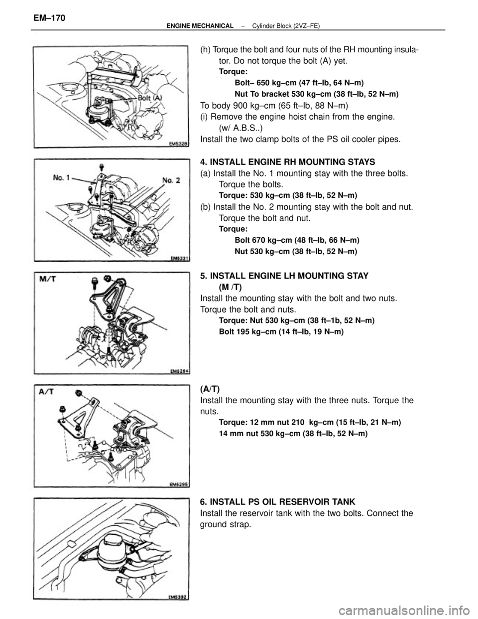
4. INSTALL ENGINE RH MOUNTING STAYS
(a) Install the No. 1 mounting stay with the three bolts.
Torque the bolts.
Torque: 530 kg±cm (38 ft±Ib, 52 N±m)
(b) Install the No. 2 mounting stay with the bolt and nut.
Torque the bolt and nut.
Torque:
Bolt 670 kg±cm (48 ft±Ib, 66 N±m)
Nut 530 kg±cm (38 ft±lb, 52 N±m)
(h) Torque the bolt and four nuts of the RH mounting insula-
tor. Do not torque the bolt (A) yet.
Torque:
Bolt± 650 kg±cm (47 ft±Ib, 64 N±m)
Nut To bracket 530 kg±cm (38 ft±Ib, 52 N±m)
To body 900 kg±cm (65 ft±Ib, 88 N±m)
(i) Remove the engine hoist chain from the engine.
(w/ A.B.S..)
Install the two clamp bolts of the PS oil cooler pipes.
5. INSTALL ENGINE LH MOUNTING STAY
(M /T)
Install the mounting stay with the bolt and two nuts.
Torque the bolt and nuts.
Torque: Nut 530 kg±cm (38 ft±1b, 52 N±m)
Bolt 195 kg±cm (14 ft±Ib, 19 N±m)
(A/T)
Install the mounting stay with the three nuts. Torque the
nuts.
Torque: 12 mm nut 210 kg±cm (15 ft±Ib, 21 N±m)
14 mm nut 530 kg±cm (38 ft±Ib, 52 N±m)
6. INSTALL PS OIL RESERVOIR TANK
Install the reservoir tank with the two bolts. Connect the
ground strap.
± ENGINE MECHANICALCylinder Block (2VZ±FE)EM±170
Page 1351 of 2389

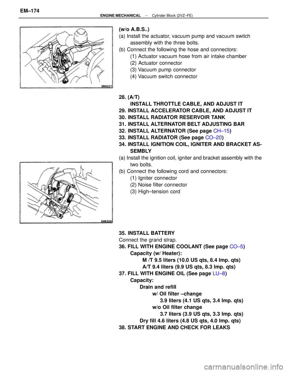
28. (A/T)
INSTALL THROTTLE CABLE, AND ADJUST IT
29. INSTALL ACCELERATOR CABLE, AND ADJUST IT
30. INSTALL RADIATOR RESERVOIR TANK
31. INSTALL ALTERNATOR BELT ADJUSTING BAR
32. INSTALL ALTERNATOR (See page CH±15)
33. INSTALL RADIATOR (See page CO±20)
34. INSTALL IGNITION COIL, IGNITER AND BRACKET AS-
SEMBLY
(a) Install the ignition coil, igniter and bracket assembly with the
two bolts.
(b) Connect the following cord and connectors:
(1) Igniter connector
(2) Noise filter connector
(3) High±tension cord
35. INSTALL BATTERY
Connect the grand strap.
36. FILL WITH ENGINE COOLANT (See page CO±5)
Capacity (w/ Heater):
M /T 9.5 liters (10.0 US qts, 8.4 Imp. qts)
A/T 9.4 liters (9.9 US qts, 8.3 Imp. qts)
37. FILL WITH ENGINE OIL (See page LU±8)
Capacity:
Drain and refill
w/ Oil filter ±change
3.9 liters (4.1 US qts, 3.4 Imp. qts)
w/o Oil filter change
3.7 liters (3.9 US qts, 3.3 Imp. qts)
Dry fill 4.6 liters (4.8 US qts, 4.0 Imp. qts)
38. START ENGINE AND CHECK FOR LEAKS (w/o A.B.S..)
(a) Install the actuator, vacuum pump and vacuum switch
assembly with the three bolts.
(b) Connect the following the hose and connectors:
(1) Actuator vacuum hose from air intake chamber
(2) Actuator connector
(3) Vacuum pump connector
(4) Vacuum switch connector
± ENGINE MECHANICALCylinder Block (2VZ±FE)EM±174
Page 1352 of 2389
39. PERFORM ENGINE ADJUSTMENT
(a) Adjust the alternator drive belt.
(See page CH±3)
Drive belt tension: New belt 175 + 5 Ib
Used belt 115 + 20 Ib
(b) Adjust PS pump drive belt.
Drive belt tension: New belt 125 + 25 Ib
Used belt 80 + 20 lb
(c) Adjust the ignition timing.
(See page IG±21 )
Ignition timing:
10°BTDC @ idle
(w/ Terminals TE1 and E1 connected)
(d) Adjust the valve clearance.
Valve clearance:
Intake 0.13 ± 0.23 mm (0. 005 ± 0.009 in.)
Exhaust 0.27 ± 0.37 mm l0.011 ± 0.015 in.)
40. INSTALL HOOD
41. PERFORM ROAD TEST
Check for abnormal noise, shock, slippage, correct shift
points and smooth operation.
42. RECHECK ENGINE COOLANT AND ENGINE OIL
LEVELS
± ENGINE MECHANICALCylinder Block (2VZ±FE)EM±175
Page 1370 of 2389
2. CONNECT STEERING KNUCKLE TO SHOCK
ABSORBER
NOTICE: Apply engine oil to the threads of the two bolts.
(a) Connect the steering knuckle to the shock absorber
lower bracket.
(b) Insert the bolts and align the matchmarks of the camber
adjusting cam.
(c) Torque the nuts.
Torque: 3,100 kg±cm (224 ft±Ib, 304 N±m)
3. CONNECT TIE ROD END TO STEERING KNUCKLE
Torque the castle nut and secure it with a new cotter pin.
Torque: 500 kg±cm (36 ft±Ib, 49 N±m)
INSTALLATION OF FRONT AXLE HUB
(See page FA ± 7)
1. INSTALL STEERING KNUCKLE TO LOWER
SUSPENSION ARM
install the steering knuckle to the lower suspension arm,
and temporarily install the nut.
4. TORQUE BALL JOINT TO LOWER ARM
Install and torque the castle nut and secure it with a new
cotter pin.
Torque: 1,250 kg±cm (90 ft±lb, 123 N±m)
5. INSTALL ROTOR DISC TO AXLE HUB
6. INSTALL DISC BRAKE CALIPER TO STEERING
KNUCKLE
Torque: 1,190 kg±cm (86 ft±Ib, 117 N±m)
± FRONT AXLE AND SUSPENSIONFront Axle HubFA±13
Page 1373 of 2389
REMOVAL OF FRONT DRIVE SHAFT
1. REMOVE COTTER PIN, LOCK NUT CUP AND LOCK NUT
(a) Remove the cotter pin and lock nut cap.
(b) Loosen the bearing lock nut while depressing the
brake pedal.
2. REMOVE ENGINE UNDER COVER
4. DRAIN OUT GEAR OIL FLUID
5. DISCONNECT TIE ROD END FROM STEERING
KNUCKLE
(a) Remove the cotter pin and nut from the steering
knuckle.
(b) Using SST, disconnect the tie rod end from the steer-
ing knuckle.
SST 09628±62011
NOTICE: The hub bearing could be damaged if it is
subjects to the vehicle weight, such as when moving
the vehicle with the drive shaft removed. Therefore, if
it is bearing first support it with SST.
SST 09608±16041 (09608±02020,09608±02040)
6. DISCONNECT STEERING KNUCKLE FROM LOWER
BALL JOINT
Remove the two bolts and disconnect the steering
knuckle from lower ball joint. 3. REMOVE FRONT FENDER APRON SEAL
± FRONT AXLE AND SUSPENSIONFront Drive Shaft (FWD SV21 )FA±16