1986 TOYOTA CAMRY V20 engine oil
[x] Cancel search: engine oilPage 1854 of 2389
![TOYOTA CAMRY V20 1986 Service Information 6. WARM UP ENGINE
Allow the engine to normal operating temperature.
7. CONNECT TACHOMETER AND TIMING LIGHT TO
ENGINE
Connect the tachometer test probe to terminal IG [±] of the
check connector.
NOTIC TOYOTA CAMRY V20 1986 Service Information 6. WARM UP ENGINE
Allow the engine to normal operating temperature.
7. CONNECT TACHOMETER AND TIMING LIGHT TO
ENGINE
Connect the tachometer test probe to terminal IG [±] of the
check connector.
NOTIC](/manual-img/14/57449/w960_57449-1853.png)
6. WARM UP ENGINE
Allow the engine to normal operating temperature.
7. CONNECT TACHOMETER AND TIMING LIGHT TO
ENGINE
Connect the tachometer test probe to terminal IG [±] of the
check connector.
NOTICE:
wNEVER allow the tachometer test probe to touch ground
as it could result in damage to the igniter
and/or ignition coil.
wAs some tachometers are not compatible with this igni-
tion system, we recommended that you confirm the
compatibility of your unit before use.
8. ADJUST IGNITION TIMING
(a) Check the idle speed.
Idle speed: 700
+ 50 rpm
(b) Using SST connect terminals TE1 and E1 of the check con-
nector.
SST 09843±18020
(c) Using a timing light, check the ignition timing.
Ignition timing: 10°6TDC @ idle
(Transmission in N range)
(d) Loosen the two hold±down bolts, and adjust by turning the
distributor.
(e) Tighten the hold±down bolts, and recheck the ignition timing.
Torque: 185 kg±cm (13 ft±Ib, 18 N±m)
9. FURTHER CHECK IGNITION TIMING
Ignition timing: 10°BTDC @ idle
(Transmission in N range)
HINT: The timing mark moves in a range between 13°
and 27°.
10. DISCONNECT TACHOMETER AND TIMING LIGHT
FROM ENGINE (f) Remove SST.
SST 09843±18020
± IGNITION SYSTEMDistributor (2VZ±FE)IG±21
Page 1858 of 2389
GENERAL REPAIR INSTRUCTIONS
1. Use fender seat and floor covers to keep the vehicle clean
and prevent damage.
2. During disassembly, keep parts in the appropriate order to
facilitate reassembly.
3. Observe the following:
(a) Before performing electrical work, disconnect the neg-
ative cable from the battery terminal.
(b) If it is necessary to disconnect the battery for inspection
or repair, always disconnect the cable from the nega-
tive H terminal which is grounded to the vehicle body.
(c) To prevent damage to the battery terminal post, loosen
the terminal nut and raise the cable straight up
without twisting or prying it.
(d) Clean the battery terminal posts and cable terminals
with a shop rag.
o not scrape them with a file or other
abrasive objects.
(e) Install the cable terminal to the battery post with
the nut loose, and tighten the nut after installation. Do
not use a hammer to tap the terminal onto the post.
(f) Be sure the cover for the positive (+) terminal is properly
in place.
4. Check hose and wiring connectors to make sure that they are
secure and correct.
5. Non±reusable parts
(a) Always replace cotter pins, gaskets, 0±rings and oil
seals etc. with new ones.
(b) Non±reusable parts are indicated in the component il-
lustrations by the ºrº symbol.
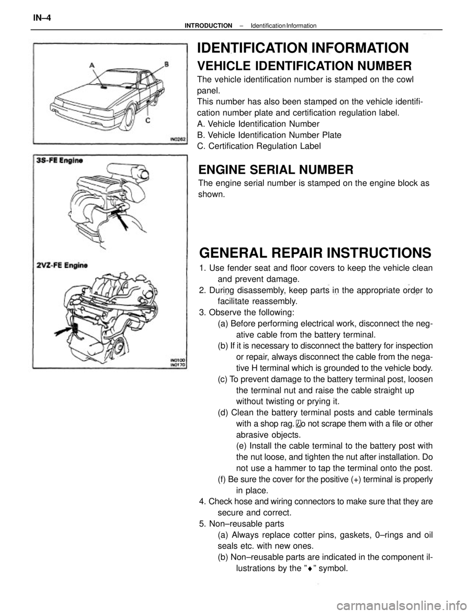
IDENTIFICATION INFORMATION
VEHICLE IDENTIFICATION NUMBER
The vehicle identification number is stamped on the cowl
panel.
This number has also been stamped on the vehicle identifi-
cation number plate and certification regulation label.
A. Vehicle Identification Number
B. Vehicle Identification Number Plate
C. Certification Regulation Label
ENGINE SERIAL NUMBER
The engine serial number is stamped on the engine block as
shown.
± INTRODUCTIONIdentification InformationIN±4
Page 1859 of 2389
GENERAL REPAIR INSTRUCTIONS
1. Use fender seat and floor covers to keep the vehicle clean
and prevent damage.
2. During disassembly, keep parts in the appropriate order to
facilitate reassembly.
3. Observe the following:
(a) Before performing electrical work, disconnect the neg-
ative cable from the battery terminal.
(b) If it is necessary to disconnect the battery for inspection
or repair, always disconnect the cable from the nega-
tive H terminal which is grounded to the vehicle body.
(c) To prevent damage to the battery terminal post, loosen
the terminal nut and raise the cable straight up
without twisting or prying it.
(d) Clean the battery terminal posts and cable terminals
with a shop rag.
o not scrape them with a file or other
abrasive objects.
(e) Install the cable terminal to the battery post with
the nut loose, and tighten the nut after installation. Do
not use a hammer to tap the terminal onto the post.
(f) Be sure the cover for the positive (+) terminal is properly
in place.
4. Check hose and wiring connectors to make sure that they are
secure and correct.
5. Non±reusable parts
(a) Always replace cotter pins, gaskets, 0±rings and oil
seals etc. with new ones.
(b) Non±reusable parts are indicated in the component il-
lustrations by the ºrº symbol.
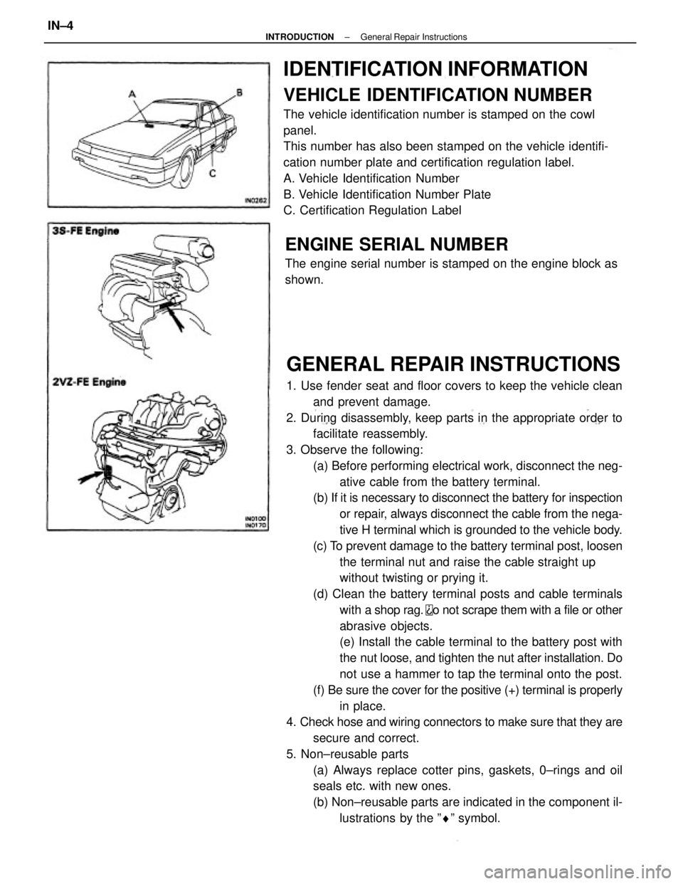
IDENTIFICATION INFORMATION
VEHICLE IDENTIFICATION NUMBER
The vehicle identification number is stamped on the cowl
panel.
This number has also been stamped on the vehicle identifi-
cation number plate and certification regulation label.
A. Vehicle Identification Number
B. Vehicle Identification Number Plate
C. Certification Regulation Label
ENGINE SERIAL NUMBER
The engine serial number is stamped on the engine block as
shown.
± INTRODUCTIONGeneral Repair InstructionsIN±4
Page 1861 of 2389
PRECAUTIONS FOR VEHICLES EQUIPPED WITH A
CATALYTIC CONVERTER
CAUTION: If large amounts of unburned gasoline flow into the converter, it may overheat
and create a fire hazard. To prevent this, observe the following precautions and
explain them to your customer.
1. Use only unleaded gasoline.
2. Avoid prolonged idling.
Avoid running the engine at idle speed for more than 20
minutes.
3. Avoid spark jump test.
(a) Spark jump test only when absolutely necessary. Perform this test as rapidly as pos-
sible.
(b) While testing, never race the engine.
4. Avoid prolonged engine compression measurement.
Engine compression tests must be made as rapidly as possible.
5. Do not run engine when fuel tank is nearly empty.
This may cause the engine to misfire and create an extra
load on the converter.
6. Avoid coasting with ignition turned off and prolonged braking.
7. Do not dispose of used catalyst along with parts contaminated with gasoline or oil.(f) When steam cleaning an engine, protect the distribu-
tor, air filter and VCV from water.
(g) Never use an impact wrench to remove or install tem-
perature switches or temperature sensors.
(h) When checking continuity at the wire connector, insert
the tester probe carefully to prevent terminals from
bending.
(i) When using a vacuum gauge, never force the hose
onto a connector that is too large. Use a step±down
adapter instead. Once the hose has been stretched,
it may leak.
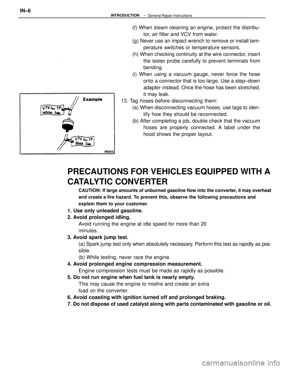
13. Tag hoses before disconnecting them:
(a) When disconnecting vacuum hoses, use tags to iden-
tify how they should be reconnected.
(b) After completing a job, double check that the vacuum
hoses are properly connected. A label under the
hood shows the proper layout.
± INTRODUCTIONIN±6General Repair Instructions
Page 1862 of 2389
PRECAUTIONS FOR VEHICLES EQUIPPED WITH A
CATALYTIC CONVERTER
CAUTION: If large amounts of unburned gasoline flow into the converter, it may overheat
and create a fire hazard. To prevent this, observe the following precautions and
explain them to your customer.
1. Use only unleaded gasoline.
2. Avoid prolonged idling.
Avoid running the engine at idle speed for more than 20
minutes.
3. Avoid spark jump test.
(a) Spark jump test only when absolutely necessary. Perform this test as rapidly as pos-
sible.
(b) While testing, never race the engine.
4. Avoid prolonged engine compression measurement.
Engine compression tests must be made as rapidly as possible.
5. Do not run engine when fuel tank is nearly empty.
This may cause the engine to misfire and create an extra
load on the converter.
6. Avoid coasting with ignition turned off and prolonged braking.
7. Do not dispose of used catalyst along with parts contaminated with gasoline or oil.(f) When steam cleaning an engine, protect the distribu-
tor, air filter and VCV from water.
(g) Never use an impact wrench to remove or install tem-
perature switches or temperature sensors.
(h) When checking continuity at the wire connector, insert
the tester probe carefully to prevent terminals from
bending.
(i) When using a vacuum gauge, never force the hose
onto a connector that is too large. Use a step±down
adapter instead. Once the hose has been stretched,
it may leak.
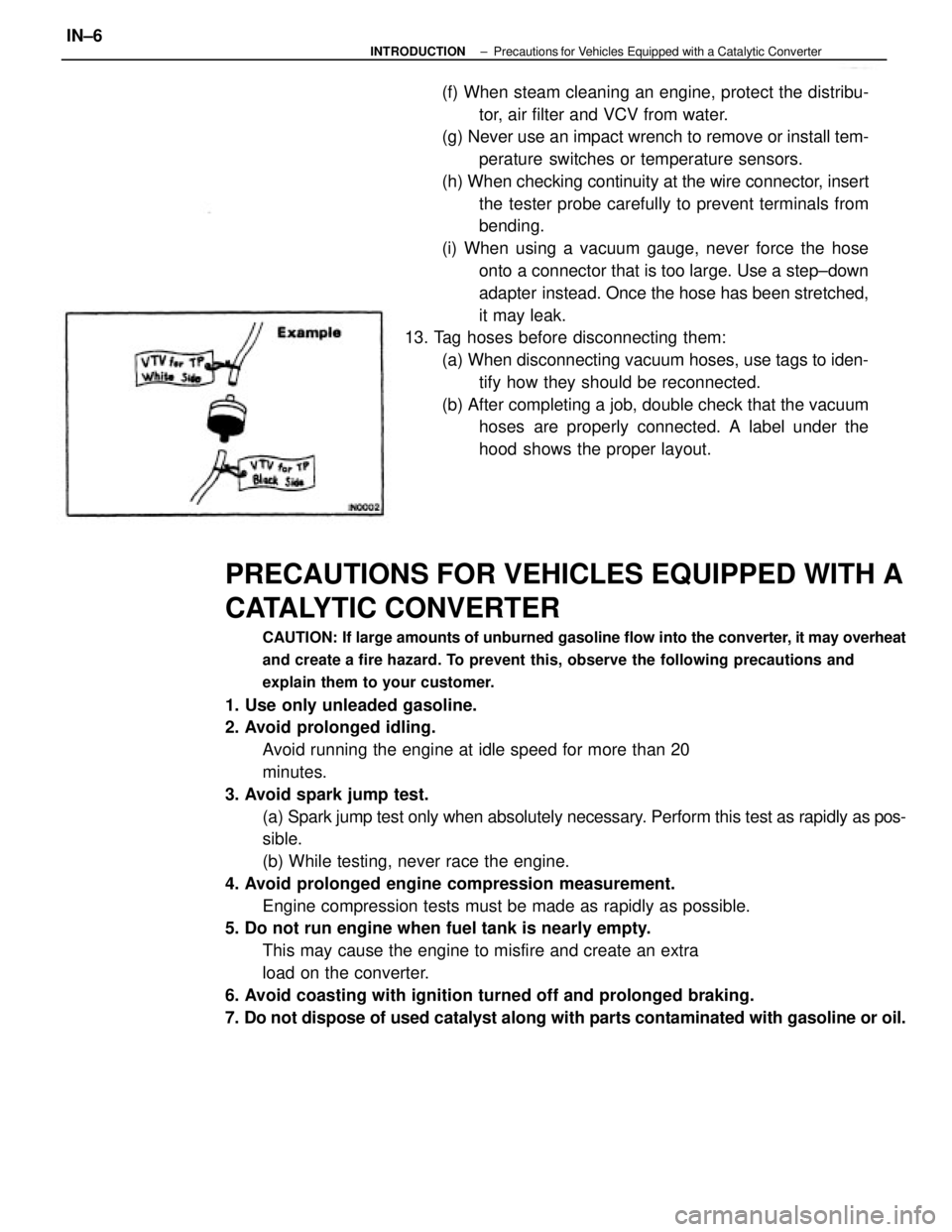
13. Tag hoses before disconnecting them:
(a) When disconnecting vacuum hoses, use tags to iden-
tify how they should be reconnected.
(b) After completing a job, double check that the vacuum
hoses are properly connected. A label under the
hood shows the proper layout.
± INTRODUCTIONPrecautions for Vehicles Equipped with a Catalytic ConverterIN±6
Page 1889 of 2389
A pressure feeding lubrication system has been adopted to supply oil to the moving parts of this engine.
The lubrication system consists of an oil pan, oil pump, oil filter and other external parts which supply oil
to the moving parts in the engine block The oil circuit is shown in the illustration at the top of the pre-
vious page. Oil from the oil pan is pumped up by the oil pump. After it passes through the oil filter, it is
fed through the various oil holes in the crankshaft and cylinder block. After passing through the cylinder
block and performing its lubricating function, the oil is returned by gravity to the oil pan. A dipstick on the
center left side of the cylinder block is provided to check the oil level.
OIL PUMP
The oil pump pumps up oil from the oil pan and sends it under pressure to the various parts of the en-
gine.
An oil strainer is mounted in front of the inlet to the oil pump. The oil pump itself is a trochoid±type
pump, inside of which is a drive rotor and a driven rotor. 'When the drive rotor rotates, the driven rotor
rotates in the same direction, and since the axis of the driven rotor shaft is different from the center of
the driven rotor, the space between the two rotors is changed as they rotate. Oil is drawn in when the
space is wide and is discharged when the space in narrow.
OIL PRESSURE REGULATOR (RELIEF VALVE)
At high engine speeds, the engine oil supplied by the oil pump exceeds the capacity of the engine to
utilize it.
For that reason, the oil pressure regulator works to prevent an oversupply of oil. During normal oil sup-
ply, a coil spring and valve keep the by±pass closed, but when too much oil is being fed, the pressure
become extremely high, overpowering the force of the spring and opening the valves. This allows the
excess oil to flow through the valve and return to the oil pan.
OIL FILTER
The oil filter is a full flow type filter with a built±in paper filter element, Particles of metal from wear, air-
born dirt, carbon and other impurities can get in the oil during use and could cause accelerated wear or
seizing if allowed to circulate through the engine. The oil filter, integrated into the oil line, removes these
impurities as the oil passes through it. The filter is mounted outside the engine to simplify replacement of
the filter element.
A relief valve is also included ahead of the filter element to relieve the high oil pressure in case the filter
element becomes clogged with impurities. The relief valve opens when the oil pressure overpowers the
force of the spring. Oil passing through the relief valve by±passes the oil filter and flows directly into the
main oil hole in the engine.
± LUBRICATION SYSTEMDescriptionLU±4
Page 1890 of 2389
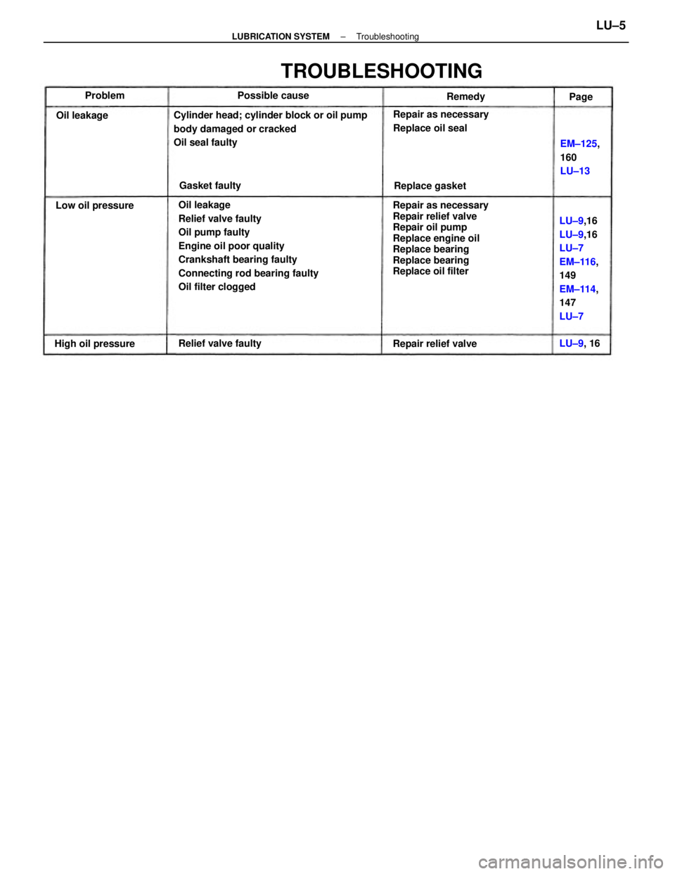
Oil leakage
Relief valve faulty
Oil pump faulty
Engine oil poor quality
Crankshaft bearing faulty
Connecting rod bearing faulty
Oil filter cloggedRepair as necessary
Repair relief valve
Repair oil pump
Replace engine oil
Replace bearing
Replace bearing
Replace oil filter Cylinder head; cylinder block or oil pump
body damaged or cracked
Oil seal faulty
LU±9,16
LU±9,16
LU±7
EM±116,
149
EM±114,
147
LU±7
TROUBLESHOOTING
Repair as necessary
Replace oil seal
EM±125,
160
LU±13
Relief valve faulty
Repair relief valve High oil pressureLow oil pressureReplace gasket Possible cause
Gasket faulty Oil leakageRemedy
LU±9, 16 Problem
Page
± LUBRICATION SYSTEMTroubleshootingLU±5
Page 1891 of 2389
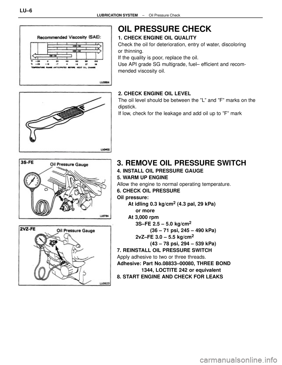
3. REMOVE OIL PRESSURE SWITCH
4. INSTALL OIL PRESSURE GAUGE
5. WARM UP ENGINE
Allow the engine to normal operating temperature.
6. CHECK OIL PRESSURE
Oil pressure:
At idling 0.3 kg/cm
2 (4.3 pal, 29 kPa)
or more
At 3,000 rpm
3S±FE 2.5 ± 5.0 kg/cm
2
(36 ± 71 psi, 245 ± 490 kPa)
2vZ±FE 3.0 ± 5.5 kg/cm
2
(43 ± 78 psi, 294 ± 539 kPa)
7. REINSTALL OIL PRESSURE SWITCH
Apply adhesive to two or three threads.
Adhesive: Part No.08833±00080, THREE BOND
1344, LOCTITE 242 or equivalent
8. START ENGINE AND CHECK FOR LEAKS
OIL PRESSURE CHECK
1. CHECK ENGINE OIL QUALITY
Check the oil for deterioration, entry of water, discoloring
or thinning.
If the quality is poor, replace the oil.
Use API grade SG multigrade, fuel± efficient and recom-
mended viscosity oil.
2. CHECK ENGINE OIL LEVEL
The oil level should be between the ºLº and ºFº marks on the
dipstick.
If low, check for the leakage and add oil up to ºFº mark
± LUBRICATION SYSTEMOil Pressure CheckLU±6