Page 2248 of 2389
Shift and select lever X Transmission case
Lock bolt x Transmission case
Engine front mounting X Transaxle
Stiffener plate
Engine rear end plate
Engine mounting left bracket x Transaxle
Transfer right case x Actuator bracket
Transaxle assembly x Engine
Input shaft _
3rd and 4th gear journal diameter
5th gear journal diameter
Runout
Output shaft
Roller bearing journal diameter
1 st and 2nd gear journal diameter
Runout
Gear thrust clearance
MANUAL TRANSAXLE (E52)
Specifications
Shift fork to hub sleeve clearance
Synchronizer ring to gear clearane
Output shaft bearing preload (at starting)
Torque Specifications (Cont'd)
Gear oil clearance
1 st and 4thPart tightened
Reverse idler 2nd and 3rd
5th
± SERVICE SPECIFICATIONSManual Transaxle (E52)A±11
Page 2252 of 2389
Transaxle X Engine 12 mm bolt
10 mm bolt
Transaxle X Engine front mounting
Insulator x Engine front mounting
Transaxle X Stiffener plate
Transaxle X Engine mounting left stay
Engine left mounting x Left stay
Engine mounting bracket X Body bracket
Transaxle x Rear end plate
Transaxle x Case protector
Lower arm x Body
Stabilizer bar x Body
Drive shaft X Side gear shaft
Ball joint X Steering knuckle
Tie rod end x Steering knuckle
Drive shaft x Axle hub
Center member x Body
Center member X Engine mounting
Lower crossmember X Body
Clutch release cylinder x Transaxleoil cooler tube x Elbow
Selecting bellcrank set bolt
Transaxle X Engine
Specifications (Cont'd)
Part tightened
± SERVICE SPECIFICATIONSManual Transaxle (E52)A±15
Page 2253 of 2389
Line pressure (wheel locked)
Engine idling
At stall (Throttle valve fully opened)
Engine stall revolution
Time lag
Engine idle speed (A/C OFF)
Throttle cable adjustment (Throttle valve fully opened)
* O/D main switch OFF
NOTE:
(1) In the 2 and L ranges, all stages lock±up is OFF.
(2) In the following cases, the lock±up will be released regardless of the lock±up pattern.
wWhen the throttle is completely closed.
wWhen the brake light switch is ON.
Body clearance
Tip clearance
Side clearance
Pump body bushing inside diameter
Stator shaft bushing inside diameter
AUTOMATIC TRANSAXLE (A140E)
Specifications
Throttle valve fully open [ ] Fully closed
Piston stroke
Piston rod lengthThrottle valve opening 5 %
Second
coast brake
km/h (mph) Shift
schedule
Lock±up
point
Lock±up OFFkm/h (mph)
Lock±up ON NORM
P'WR NORM
PWR
Oil pumpD range
D range 2 range
L range
NORMNORM
O/D O/D
PWRPWR
2nd 3rd
2nd3rd
± SERVICE SPECIFICATIONSAutomatic Tiransaxle Al 40E)A±16
Page 2256 of 2389
Drive plate x Crank shaft
Torque converter X Drive plate
Oil pump x Transaxle case
Oil pump body X Stator shaft
Second coast brake band guide
Upper valve body x Lower valve body
Valve body
Accumulator cover
Oil strainer
Oil pan
Oil pan drain plug
Cooler pipe union nut
Testing plug
Parking lock pawl bracket
Overdrive case x Transaxle case
Neutral start switch bolt
Neutral start switch nutSide bearing adjusting shim thickness
(cont'd)
Specifications (Cont'd)
Torque Specifications
Transaxle case x Engine Differential
(cont'd)
Part tightened
± SERVICE SPECIFICATIONSAutomatic Transaxle (Al 40E)A±19
Page 2257 of 2389

At stall
(Throttle valve fully opened)
Engine stall revolution
Time lag N range ±
N range ±
Engine idling speed (A/C OFF)
Throttle cable adjustment (Throttle valve fully opened)
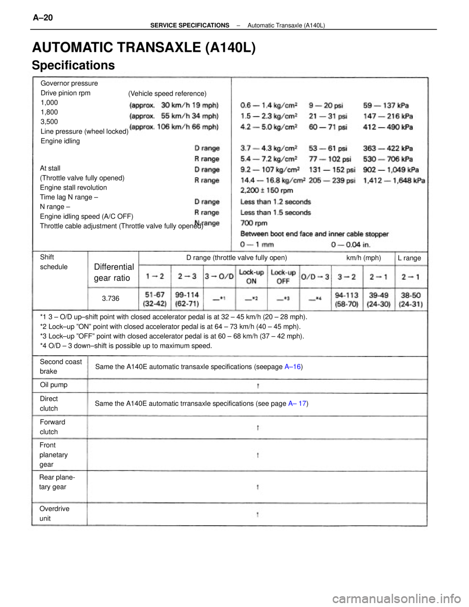
*1 3 ± O/D up±shift point with closed accelerator pedal is at 32 ± 45 km/h (20 ± 28 mph).
*2 Lock±up ºONº point with closed accelerator pedal is at 64 ± 73 km/h (40 ± 45 mph).
*3 Lock±up ºOFFº point with closed accelerator pedal is at 60 ± 68 km/h (37 ± 42 mph).
*4 O/D ± 3 down±shift is possible up to maximum speed.Governor pressure
Drive pinion rpm
1,000
1,800
3,500
Line pressure (wheel locked)
Engine idling
AUTOMATIC TRANSAXLE (A140L)
Specifications
Same the A140E automatic transaxle specifications (seepage A±16)
Same the A140E automatic trransaxle specifications (see page A± 17) D range (throttle valve fully open) (Vehicle speed reference)
Rear plane-
tary gearFront
planetary
gear
Differential
gear ratio
Second coast
brake
Overdrive
unitShift
schedule
Forward
clutchkm/h (mph)
Direct
clutchOil pumpL range
3.736
± SERVICE SPECIFICATIONSAutomatic Transaxle (A140L)A±20
Page 2259 of 2389
Line pressure (wheel locked)
Engine idling
At stall
Engine stall revolution
Time lag N range ±
N range ±
Engine idle speed (A/C OFF)
Throttle cable adjustment (Throttle valve fully opened)
Body clearance
Tip clearance
Side clearance
Pump body bushing inside diameter
Stator shaft bushing inside diameter
Front side
Rear side
AUTOMATIC TRANSAXLE (A540E)
Specifications
Between boot end face and inner cable stopper
Throttle valve fully open [Fu lly closed]
Piston stroke
Piston rod lengthThrottle valve opening 5%
Second
coast brake
* O/D switch OFF Shift
schedule
Lock±up
pointkm/h (mph)
Lock±up OFFkm/h (mph)
Lock±up ON NORM
PWR
NORM
PWR
Oil pumpD range
D range2 range
L rangeNORM
NORM
PW RPWR
± SERVICE SPECIFICATIONSAutomatic Transaxle (A540E)A±22
Page 2323 of 2389

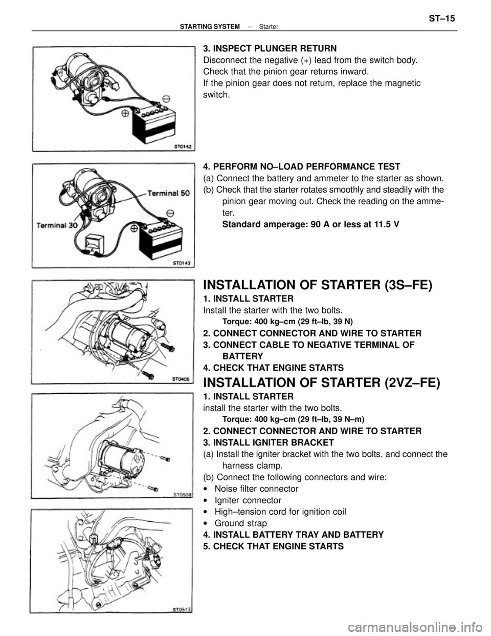
INSTALLATION OF STARTER (3S±FE)
1. INSTALL STARTER
Install the starter with the two bolts.
Torque: 400 kg±cm (29 ft±Ib, 39 N)
2. CONNECT CONNECTOR AND WIRE TO STARTER
3. CONNECT CABLE TO NEGATIVE TERMINAL OF
BATTERY
4. CHECK THAT ENGINE STARTS
INSTALLATION OF STARTER (2VZ±FE)
1. INSTALL STARTER
install the starter with the two bolts.
Torque: 400 kg±cm (29 ft±Ib, 39 N±m)
2. CONNECT CONNECTOR AND WIRE TO STARTER
3. INSTALL IGNITER BRACKET
(a) Install the igniter bracket with the two bolts, and connect the
harness clamp.
(b) Connect the following connectors and wire:
wNoise filter connector
wIgniter connector
wHigh±tension cord for ignition coil
wGround strap
4. INSTALL BATTERY TRAY AND BATTERY
5. CHECK THAT ENGINE STARTS 4. PERFORM NO±LOAD PERFORMANCE TEST
(a) Connect the battery and ammeter to the starter as shown.
(b) Check that the starter rotates smoothly and steadily with the
pinion gear moving out. Check the reading on the amme-
ter.
Standard amperage: 90 A or less at 11.5 V 3. INSPECT PLUNGER RETURN
Disconnect the negative (+) lead from the switch body.
Check that the pinion gear returns inward.
If the pinion gear does not return, replace the magnetic
switch.
± STARTING SYSTEMStarterST±15
Page 2351 of 2389

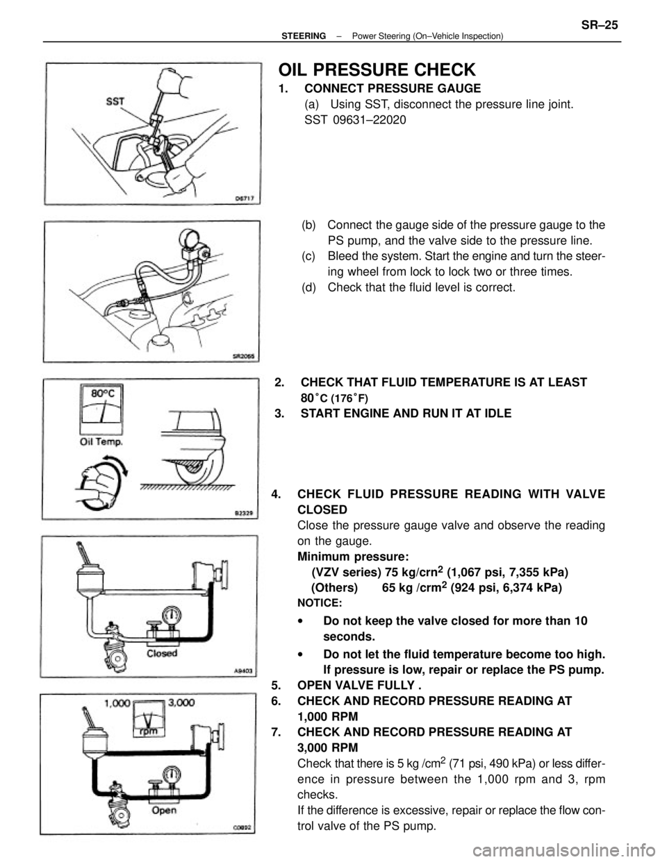
4. CHECK FLUID PRESSURE READING WITH VALVE
CLOSED
Close the pressure gauge valve and observe the reading
on the gauge.
Minimum pressure:
(VZV series) 75 kg/crn
2 (1,067 psi, 7,355 kPa)
(Others) 65 kg /crm
2 (924 psi, 6,374 kPa)
NOTICE:
wDo not keep the valve closed for more than 10
seconds.
wDo not let the fluid temperature become too high.
If pressure is low, repair or replace the PS pump.
5. OPEN VALVE FULLY .
6. CHECK AND RECORD PRESSURE READING AT
1,000 RPM
7. CHECK AND RECORD PRESSURE READING AT
3,000 RPM
Check that there is 5 kg /cm
2 (71 psi, 490 kPa) or less differ-
ence in pressure between the 1,000 rpm and 3, rpm
checks.
If the difference is excessive, repair or replace the flow con-
trol valve of the PS pump.(b) Connect the gauge side of the pressure gauge to the
PS pump, and the valve side to the pressure line.
(c) Bleed the system. Start the engine and turn the steer-
ing wheel from lock to lock two or three times.
(d) Check that the fluid level is correct.
OIL PRESSURE CHECK
1. CONNECT PRESSURE GAUGE
(a) Using SST, disconnect the pressure line joint.
SST 09631±22020
2. CHECK THAT FLUID TEMPERATURE IS AT LEAST
80
°C (176°F)
3. START ENGINE AND RUN IT AT IDLE
± STEERINGPower Steering (On±Vehicle Inspection)SR±25