Page 1283 of 2389
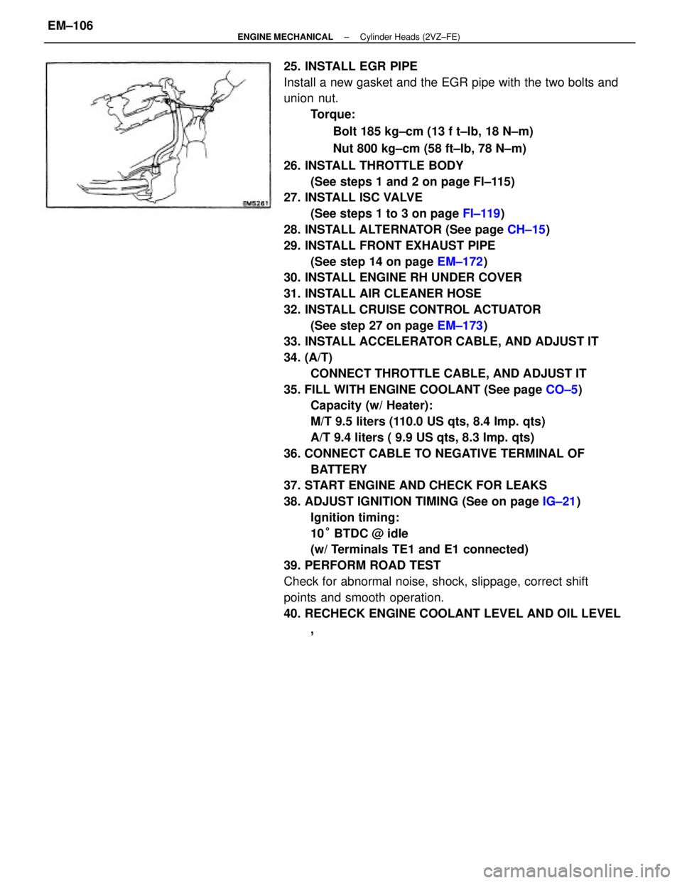
25. INSTALL EGR PIPE
Install a new gasket and the EGR pipe with the two bolts and
union nut.
Torque:
Bolt 185 kg±cm (13 f t±lb, 18 N±m)
Nut 800 kg±cm (58 ft±Ib, 78 N±m)
26. INSTALL THROTTLE BODY
(See steps 1 and 2 on page Fl±115)
27. INSTALL ISC VALVE
(See steps 1 to 3 on page FI±119)
28. INSTALL ALTERNATOR (See page CH±15)
29. INSTALL FRONT EXHAUST PIPE
(See step 14 on page EM±172)
30. INSTALL ENGINE RH UNDER COVER
31. INSTALL AIR CLEANER HOSE
32. INSTALL CRUISE CONTROL ACTUATOR
(See step 27 on page EM±173)
33. INSTALL ACCELERATOR CABLE, AND ADJUST IT
34. (A/T)
CONNECT THROTTLE CABLE, AND ADJUST IT
35. FILL WITH ENGINE COOLANT (See page CO±5)
Capacity (w/ Heater):
M/T 9.5 liters (110.0 US qts, 8.4 Imp. qts)
A/T 9.4 liters ( 9.9 US qts, 8.3 Imp. qts)
36. CONNECT CABLE TO NEGATIVE TERMINAL OF
BATTERY
37. START ENGINE AND CHECK FOR LEAKS
38. ADJUST IGNITION TIMING (See on page IG±21)
Ignition timing:
10° BTDC @ idle
(w/ Terminals TE1 and E1 connected)
39. PERFORM ROAD TEST
Check for abnormal noise, shock, slippage, correct shift
points and smooth operation.
40. RECHECK ENGINE COOLANT LEVEL AND OIL LEVEL
,
± ENGINE MECHANICALCylinder Heads (2VZ±FE)EM±106
Page 1286 of 2389
15. DISCONNECT HOSES
(a) Two heater water by±pass hoses
(b) Two fuel hoses
NOTICE: Catch leaking fuel in a container.
(c) Brake booster vacuum hose
(d) A/C control valve vacuum hoses
(e) Charcoal canister vacuum hose
16. DISCONNECT WIRES AND CONNECTORS
(a) Check connector
(b) Ground straps from LH fender apron
(e) Connectors from relay box
(d) Engine room wire connector
17. RAISE VEHICLE
NOTICE: Be sure the vehicle is securely supported.
18. REMOVE ENGINE UNDER COVERS
19. DRAIN ENGINE OIL (See page LU±7)
20. REMOVE SUSPENSION LOWER CROSSMEMBER
Remove the four bolts, two nuts and crossmember.
21. REMOVE DRIVE SHAFTS
22. (4WD) .
REMOVE PROPELLER SHAFT
23. (4WD)
REMOVE DEFECTOR FROM TRANSFER EXTENSION
HOUSING
24. REMOVE PS PUMP WITHOUT DISCONNECTING
HOSES
HINT: Put aside the pump and suspend it to the cowl with a
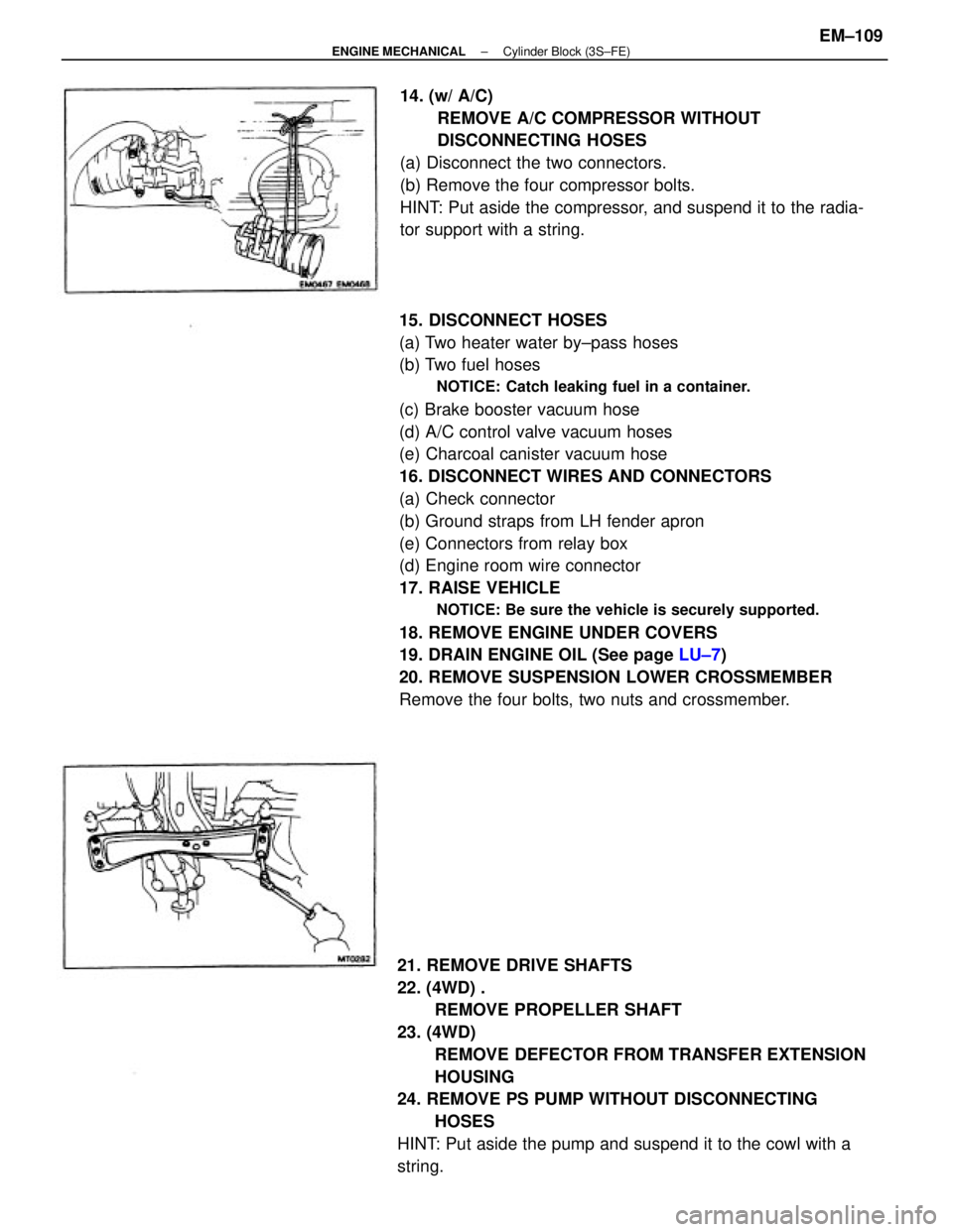
string.14. (w/ A/C)
REMOVE A/C COMPRESSOR WITHOUT
DISCONNECTING HOSES
(a) Disconnect the two connectors.
(b) Remove the four compressor bolts.
HINT: Put aside the compressor, and suspend it to the radia-
tor support with a string.
± ENGINE MECHANICALCylinder Block (3S±FE)EM±109
Page 1287 of 2389
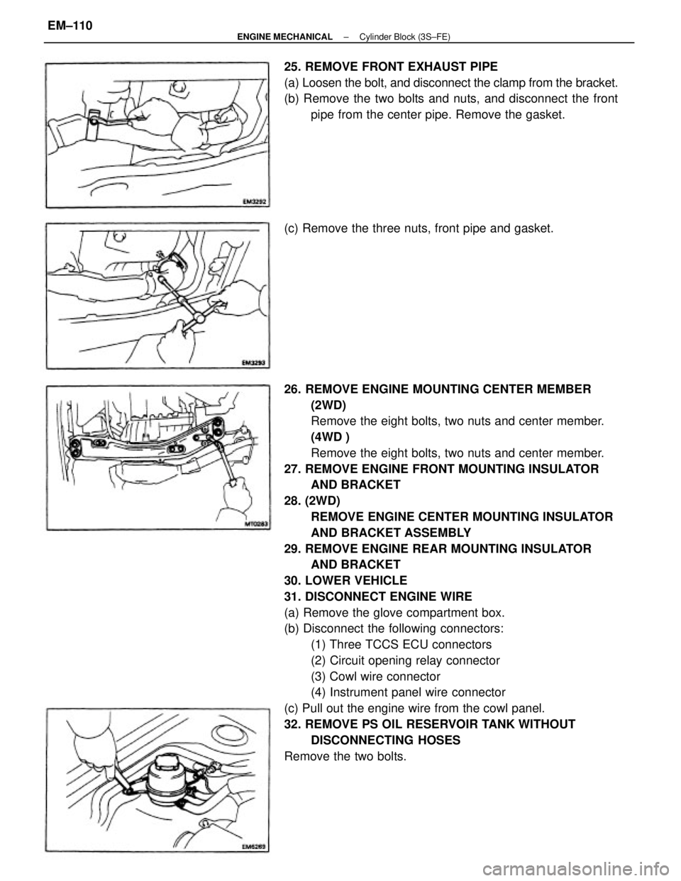
26. REMOVE ENGINE MOUNTING CENTER MEMBER
(2WD)
Remove the eight bolts, two nuts and center member.
(4WD )
Remove the eight bolts, two nuts and center member.
27. REMOVE ENGINE FRONT MOUNTING INSULATOR
AND BRACKET
28. (2WD)
REMOVE ENGINE CENTER MOUNTING INSULATOR
AND BRACKET ASSEMBLY
29. REMOVE ENGINE REAR MOUNTING INSULATOR
AND BRACKET
30. LOWER VEHICLE
31. DISCONNECT ENGINE WIRE
(a) Remove the glove compartment box.
(b) Disconnect the following connectors:
(1) Three TCCS ECU connectors
(2) Circuit opening relay connector
(3) Cowl wire connector
(4) Instrument panel wire connector
(c) Pull out the engine wire from the cowl panel.
32. REMOVE PS OIL RESERVOIR TANK WITHOUT
DISCONNECTING HOSES
Remove the two bolts. 25. REMOVE FRONT EXHAUST PIPE
(a) Loosen the bolt, and disconnect the clamp from the bracket.
(b) Remove the two bolts and nuts, and disconnect the front
pipe from the center pipe. Remove the gasket.
(c) Remove the three nuts, front pipe and gasket.
± ENGINE MECHANICALCylinder Block (3S±FE)EM±110
Page 1290 of 2389
PREPARATION FOR DISASSEMBLY
1. ( M /T)
REMOVE CLUTCH COVER AND DISC
2. ( M /T)
REMOVE FLYWHEEL
3. 1A/T)
REMOVE DRIVE PLATE
4. REMOVE REAR END PLATE
5. INSTALL ENGINE TO ENGINE STAND FOR
DISASSEMBLY
6. REMOVE ALTERNATOR (See page CH±6)
7 REMOVE DISTRIBUTOR (See page IG±13)
8. REMOVE TIMING BELT AND PULLEYS
(See page EM±23)
9. REMOVE CYLINDER HEAD (See page EM±48)
10. REMOVE WATER PUMP (See page CO±6)
11. REMOVE OIL PAN AND OIL PUMP
(See page LU±9)
± ENGINE MECHANICALCylinder Block (3S±FE)EM±113
Page 1291 of 2389
2. CHECK CONNECTING ROD THRUST CLEARANCE
Using a dial indicator, measure the thrust clearance while
moving the connecting rod back and forth.
Standard thrust clearance: 0.160 ± 0.312 mm
(0.0063 ± 0.0123 in.)
Maximum thrust clearance: 0.35 mm (0.0138 in.)
If the thrust clearance is greater than maximum replace the
connecting rod assembly. If necessary, replace the crank-
shaft.
3. REMOVE CONNECTING ROD CAPS AND CHECK OIL
CLEARANCE
(a) Using a punch or numbering stamp, place the match±
marks on the connecting rod and cap to ensure correct
reassembly.
(c) Using a plastic±faced hammer, lightly tap the connect-
ing rod bolts and lift off the connecting rod cap.
HINT: Keep the lower bearing inserted with the connect-
ing cap.
DISASSEMBLY OF CYLINDER BLOCK
(See page EM±107)
1. REMOVE REAR OIL SEAL RETAINER
Remove the six bolts, retainer and gasket.
(b) Remove the connecting rod cap nuts.
± ENGINE MECHANICALCylinder Block (3S±FE)EM±114
Page 1292 of 2389
(i) Remove the connecting rod cap.
(j) Measure the Plastigage at widest point.
Standard oil clearance:
STD 0.024 ± 0.055 mm
(0.0009 ± 0.0022 in.)
U/S 0.25 0.023 ± 0.069 mm
(0.0009 ± 0.0027 in.)
Maximum oil clearance: 0.08 mm (0.0031 in.)
If the oil clearance is greater than maximum, replace
the bearings. If necessary, replace the crankshaft. (e) Clean crank pin and bearing.
(f) Check the crank pin and bearing for pitting and
scratches.
If the crank pin or bearing are damaged, replace the
bearings.
If necessary, replace the crankshaft.
(h) Install the connecting rod cap.
(See step 6 on page EM±129)
Torque: 500 kg±cm (36 ft±lb. 49 N±m)
HINT: Do not turn the crankshaft.(d) Cover the connecting rod bolts with a short piece of
hose to protect the crankshaft from damage.
(g) Lay a strip of Plastigage across the crank pin.
± ENGINE MECHANICALCylinder Block (3S±FE)EM±115
Page 1293 of 2389
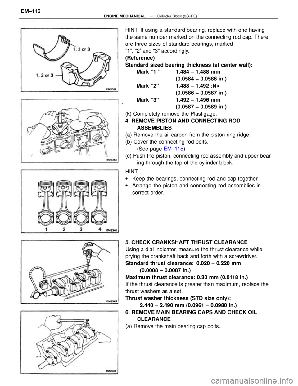
HINT: If using a standard bearing, replace with one having
the same number marked on the connecting rod cap. There
are three sizes of standard bearings, marked
º1º, º2' and ª3º accordingly.
(Reference)
Standard sized bearing thickness (at center wall):
Mark º1 º 1.484 ± 1.488 mm
(0.0584 ± 0.0586 in.)
Mark º2º 1.488 ± 1.492 :N»
(0.0586 ± 0.0587 in.)
Mark º3º 1.492 ± 1.496 mm
(0.0587 ± 0.0589 in.)
(k) Completely remove the Plastigage.
4. REMOVE PISTON AND CONNECTING ROD
ASSEMBLIES
(a) Remove the ail carbon from the piston ring ridge.
(b) Cover the connecting rod bolts.
(See page EM±115)
(c) Push the piston, connecting rod assembly and upper bear-
ing through the top of the cylinder block.
5. CHECK CRANKSHAFT THRUST CLEARANCE
Using a dial indicator, measure the thrust clearance while
prying the crankshaft back and forth with a screwdriver.
Standard thrust clearance: 0.020 ± 0.220 mm
(0.0008 ± 0.0087 in.)
Maximum thrust clearance: 0.30 mm (0.0118 in.)
If the thrust clearance is greater than maximum, replace the
thrust washers as a set.
Thrust washer thickness (STD size only):
2.440 ± 2.490 mm (0.0961 ± 0.0980 in.)
6. REMOVE MAIN BEARING CAPS AND CHECK OIL
CLEARANCE
(a) Remove the main bearing cap bolts. HINT:
wKeep the bearings, connecting rod and cap together.
wArrange the piston and connecting rod assemblies in
correct order.
± ENGINE MECHANICALCylinder Block (3S±FE)EM±116
Page 1294 of 2389
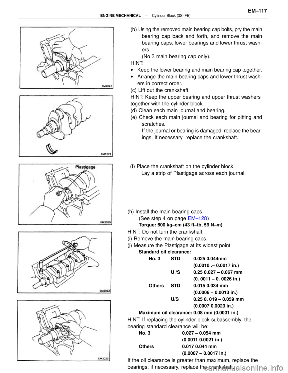
(h) Install the main bearing caps.
(See step 4 on page EM±128)
Torque: 600 kg±cm (43 ft±tb, 59 N±m)
HINT: Do not turn the crankshaft
(i) Remove the main bearing caps.
(j) Measure the Plastigage at its widest point.
Standard oil clearance:
No. 3 STD 0.025 0.044mm
(0.0010 .± 0.0017 in.)
U /S 0.25 0.027 ± 0.067 mm
(0. 0011 ± 0. 0026 in.)
Others STD 0.015 0.034 mm
(0.0006 ± 0.0013 in.)
U/S 0.25 0. 019 ± 0.059 mm
(0.0007 0.0023 in.)
Maximum oil clearance: 0.08 mm (0.0031 in.)
HINT: If replacing the cylinder block subassembly, the
bearing standard clearance will be:
No. 3 0.027 ± 0.054 mm
(0.0011 0.0021 in.)
Others 0.017 0.044 mm
(0.0007 ± 0.0017 in.)
If the oil clearance is greater than maximum, replace the
bearings, if necessary, replace the crankshaft.(b) Using the removed main bearing cap bolts, pry the main
bearing cap back and forth, and remove the main
bearing caps, lower bearings and lower thrust wash-
ers
(No.3 main bearing cap only).
HINT:
wKeep the lower bearing and main bearing cap together.
wArrange the main bearing caps and lower thrust wash-
ers in correct order.
(c) Lift out the crankshaft.
HINT: Keep the upper bearing and upper thrust washers
together with the cylinder block.
(d) Clean each main journal and bearing.
(e) Check each main journal and bearing for pitting and
scratches.
If the journal or bearing is damaged, replace the bear-
ings. If necessary, replace the crankshaft.
(f) Place the crankshaft on the cylinder block.
Lay a strip of Plastigage across each journal.
± ENGINE MECHANICALCylinder Block (3S±FE)EM±117