Page 1221 of 2389
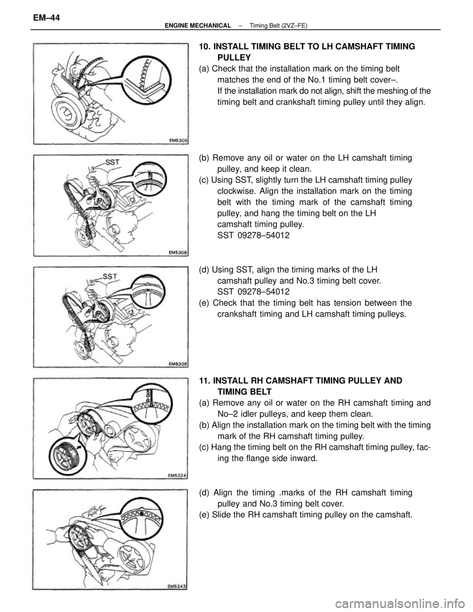
11. INSTALL RH CAMSHAFT TIMING PULLEY AND
TIMING BELT
(a) Remove any oil or water on the RH camshaft timing and
No±2 idler pulleys, and keep them clean.
(b) Align the installation mark on the timing belt with the timing
mark of the RH camshaft timing pulley.
(c) Hang the timing belt on the RH camshaft timing pulley, fac-
ing the flange side inward. (b) Remove any oil or water on the LH camshaft timing
pulley, and keep it clean.
(c) Using SST, slightly turn the LH camshaft timing pulley
clockwise. Align the installation mark on the timing
belt with the timing mark of the camshaft timing
pulley, and hang the timing belt on the LH
camshaft timing pulley.
SST 09278±54012 10. INSTALL TIMING BELT TO LH CAMSHAFT TIMING
PULLEY
(a) Check that the installation mark on the timing belt
matches the end of the No.1 timing belt cover±.
If the installation mark do not align, shift the meshing of the
timing belt and crankshaft timing pulley until they align.
(d) Using SST, align the timing marks of the LH
camshaft pulley and No.3 timing belt cover.
SST 09278±54012
(e) Check that the timing belt has tension between the
crankshaft timing and LH camshaft timing pulleys.
(d) Align the timing .marks of the RH camshaft timing
pulley and No.3 timing belt cover.
(e) Slide the RH camshaft timing pulley on the camshaft.
± ENGINE MECHANICALTiming Belt (2VZ±FE)EM±44
Page 1224 of 2389
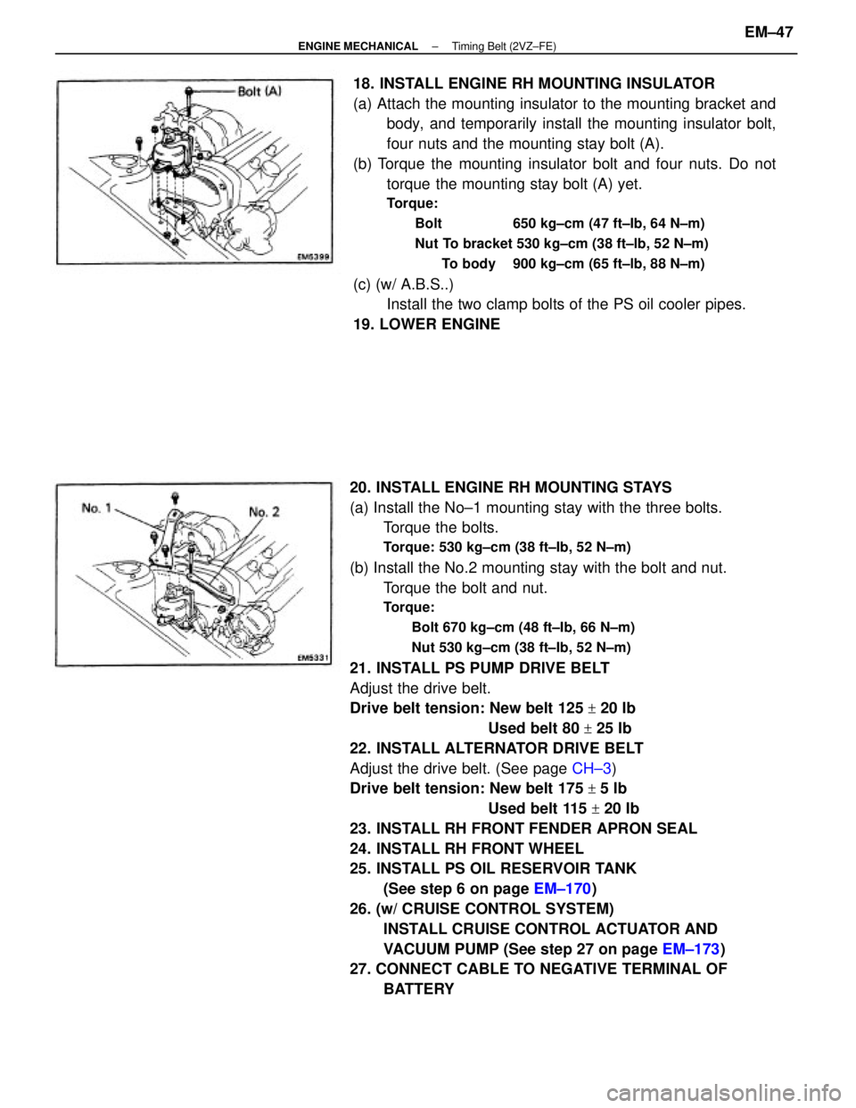
20. INSTALL ENGINE RH MOUNTING STAYS
(a) Install the No±1 mounting stay with the three bolts.
Torque the bolts.
Torque: 530 kg±cm (38 ft±Ib, 52 N±m)
(b) Install the No.2 mounting stay with the bolt and nut.
Torque the bolt and nut.
Torque:
Bolt 670 kg±cm (48 ft±Ib, 66 N±m)
Nut 530 kg±cm (38 ft±Ib, 52 N±m)
21. INSTALL PS PUMP DRIVE BELT
Adjust the drive belt.
Drive belt tension: New belt 125
+ 20 Ib
Used belt 80
+ 25 Ib
22. INSTALL ALTERNATOR DRIVE BELT
Adjust the drive belt. (See page CH±3)
Drive belt tension: New belt 175
+ 5 Ib
Used belt 115
+ 20 Ib
23. INSTALL RH FRONT FENDER APRON SEAL
24. INSTALL RH FRONT WHEEL
25. INSTALL PS OIL RESERVOIR TANK
(See step 6 on page EM±170)
26. (w/ CRUISE CONTROL SYSTEM)
INSTALL CRUISE CONTROL ACTUATOR AND
VACUUM PUMP (See step 27 on page EM±173)
27. CONNECT CABLE TO NEGATIVE TERMINAL OF
BATTERY 18. INSTALL ENGINE RH MOUNTING INSULATOR
(a) Attach the mounting insulator to the mounting bracket and
body, and temporarily install the mounting insulator bolt,
four nuts and the mounting stay bolt (A).
(b) Torque the mounting insulator bolt and four nuts. Do not
torque the mounting stay bolt (A) yet.
Torque:
Bolt 650 kg±cm (47 ft±Ib, 64 N±m)
Nut To bracket 530 kg±cm (38 ft±lb, 52 N±m)
To body 900 kg±cm (65 ft±lb, 88 N±m)
(c) (w/ A.B.S..)
Install the two clamp bolts of the PS oil cooler pipes.
19. LOWER ENGINE
± ENGINE MECHANICALTiming Belt (2VZ±FE)EM±47
Page 1226 of 2389
REMOVAL OF CYLINDER HEAD
(See page EM±48)
1. DISCONNECT CABLE FROM NEGATIVE TERMINAL
OF BATTERY
2. DRAIN ENGINE COOLANT (See page CO±4)
3. (A/T)
DISCONNECT THROTTLE CABLE AND BRACKET FROM
THROTTLE BODY
4. DISCONNECT ACCELERATOR CABLE AND BRACKET
FROM THROTTLE BODY AND AIR INTAKE CHAMBER
5. REMOVE CRUISE CONTROL ACTUATOR
(See step 9 on page EM±108)
6. REMOVE AIR CLEANER HOSE
7. REMOVE ALTERNATOR (See page CH±6)
8. REMOVE OIL PRESSURE SWITCH, ENGINE HANGERS
AND ALTERNATOR UPPER BRACKET
9. RAISE VEHICLE
NOTICE: Be sure the vehicle is securely supported.
10. REMOVE RH FRONT WHEEL
11. REMOVE ENGINE RH UNDER COVER
12. REMOVE SUSPENSION LOWER CROSSMEMBER
(See step 20 on page EM±109)
13. DISCONNECT FRONT EXHAUST PIPE FROM
CATALYTIC CONVERTER
(See step 25 on page EM±110)
14. REMOVE EXHAUST MANIFOLD AND CATALYTIC
CONVERTER ASSEMBLY
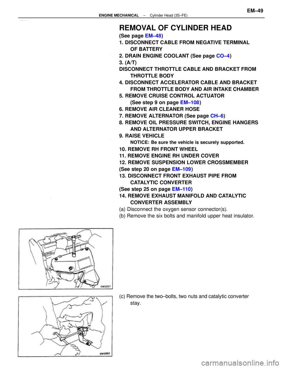
(a) Disconnect the oxygen sensor connector(s).
(b) Remove the six bolts and manifold upper heat insulator.
(c) Remove the two±bolts, two nuts and catalytic converter
stay.
± ENGINE MECHANICALCylinder Head (3S±FE)EM±49
Page 1229 of 2389
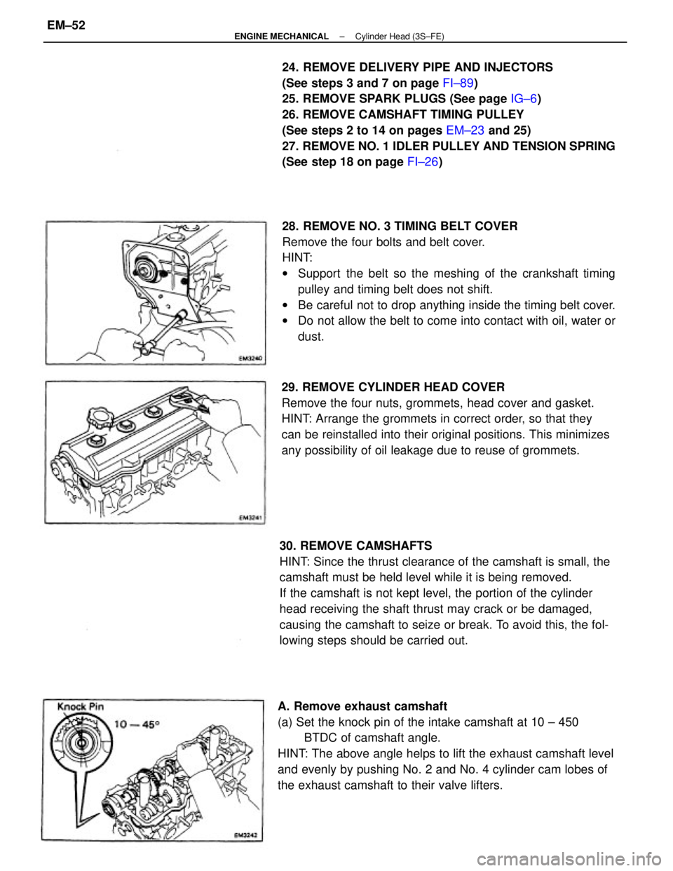
28. REMOVE NO. 3 TIMING BELT COVER
Remove the four bolts and belt cover.
HINT:
wSupport the belt so the meshing of the crankshaft timing
pulley and timing belt does not shift.
wBe careful not to drop anything inside the timing belt cover.
wDo not allow the belt to come into contact with oil, water or
dust. 24. REMOVE DELIVERY PIPE AND INJECTORS
(See steps 3 and 7 on page FI±89)
25. REMOVE SPARK PLUGS (See page IG±6)
26. REMOVE CAMSHAFT TIMING PULLEY
(See steps 2 to 14 on pages EM±23 and 25)
27. REMOVE NO. 1 IDLER PULLEY AND TENSION SPRING
(See step 18 on page FI±26)
30. REMOVE CAMSHAFTS
HINT: Since the thrust clearance of the camshaft is small, the
camshaft must be held level while it is being removed.
If the camshaft is not kept level, the portion of the cylinder
head receiving the shaft thrust may crack or be damaged,
causing the camshaft to seize or break. To avoid this, the fol-
lowing steps should be carried out.
A. Remove exhaust camshaft
(a) Set the knock pin of the intake camshaft at 10 ± 450
BTDC of camshaft angle.
HINT: The above angle helps to lift the exhaust camshaft level
and evenly by pushing No. 2 and No. 4 cylinder cam lobes of
the exhaust camshaft to their valve lifters.29. REMOVE CYLINDER HEAD COVER
Remove the four nuts, grommets, head cover and gasket.
HINT: Arrange the grommets in correct order, so that they
can be reinstalled into their original positions. This minimizes
any possibility of oil leakage due to reuse of grommets.
± ENGINE MECHANICALCylinder Head (3S±FE)EM±52
Page 1231 of 2389
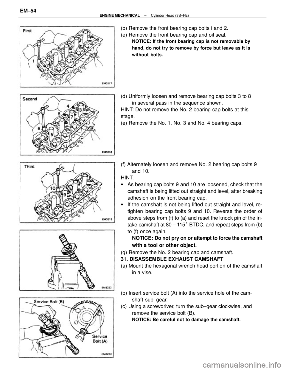
(f) Alternately loosen and remove No. 2 bearing cap bolts 9
and 10.
HINT:
wAs bearing cap bolts 9 and 10 are loosened, check that the
camshaft is being lifted out straight and level, after breaking
adhesion on the front bearing cap.
wIf the camshaft is not being lifted out straight and level, re-
tighten bearing cap bolts 9 and 10. Reverse the order of
above steps from (f) to (a) and reset the knock pin of the in-
take camshaft at 80 ± 115° BTDC, and repeat steps from (b)
to (f) once again.
NOTICE: Do not pry on or attempt to force the camshaft
with a tool or other object.
(g) Remove the No. 2 bearing cap and camshaft.
31. DISASSEMBLE EXHAUST CAMSHAFT
(a) Mount the hexagonal wrench head portion of the camshaft
in a vise.
(b) Insert service bolt (A) into the service hole of the cam-
shaft sub±gear.
(c) Using a screwdriver, turn the sub±gear clockwise, and
remove the service bolt (B).
NOTICE: Be careful not to damage the camshaft.
(d) Uniformly loosen and remove bearing cap bolts 3 to 8
in several pass in the sequence shown.
HINT: Do not remove the No. 2 bearing cap bolts at this
stage.
(e) Remove the No. 1, No. 3 and No. 4 bearing caps. (b) Remove the front bearing cap bolts i and 2.
(e) Remove the front bearing cap and oil seal.
NOTICE: If the front bearing cap is not removable by
hand, do not try to remove by force but leave as it is
without bolts.
± ENGINE MECHANICALCylinder Head (3S±FE)EM±54
Page 1233 of 2389
2. REMOVE VALVES
(a) Using SST, compress the valve spring and remove the two
keepers.
SST 09202±70010
(b) Remove the spring retainer, valve spring, valve and spring
seat.
DISASSEMBLY OF CYLINDER HEAD
(See page EM±47)
1. REMOVE VALVE LIFTERS AND SHIMS
HINT: Arrange the valves, valve springs, spring seats
and spring retainers in correct order. HINT: Arrange the valve lifters and shims in correct or-
der.
(c) Using needle±nose pliers, remove the oil seal.
± ENGINE MECHANICALCylinder Head (3S±FE)EM±56
Page 1234 of 2389
INSPECTION, CLEANING AND REPAIR OF
CYLINDER HEAD COMPONENTS
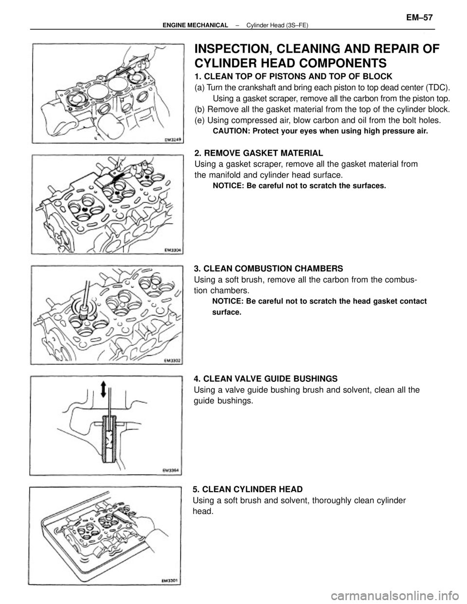
1. CLEAN TOP OF PISTONS AND TOP OF BLOCK
(a) Turn the crankshaft and bring each piston to top dead center (TDC).
Using a gasket scraper, remove all the carbon from the piston top.
(b) Remove all the gasket material from the top of the cylinder block.
(e) Using compressed air, blow carbon and oil from the bolt holes.
CAUTION: Protect your eyes when using high pressure air.
2. REMOVE GASKET MATERIAL
Using a gasket scraper, remove all the gasket material from
the manifold and cylinder head surface.
NOTICE: Be careful not to scratch the surfaces.
3. CLEAN COMBUSTION CHAMBERS
Using a soft brush, remove all the carbon from the combus-
tion chambers.
NOTICE: Be careful not to scratch the head gasket contact
surface.
4. CLEAN VALVE GUIDE BUSHINGS
Using a valve guide bushing brush and solvent, clean all the
guide bushings.
5. CLEAN CYLINDER HEAD
Using a soft brush and solvent, thoroughly clean cylinder
head.
± ENGINE MECHANICALCylinder Head (3S±FE)EM±57
Page 1236 of 2389
(b) Using a micrometer, measure the diameter of the valve
stem.
Valve stem diameter:
Intake 5.970 ± 5.985mm
(0.2350 ± 0.2356 in.)
Exhaust 5.965 ± 5.980 mm
(0.2348 ± 0.2354 in.)
(c) Subtract the valve stem diameter measurement from
the guide bushing inside diameter measurement.
Standard oil clearance:
Intake 0.025 ± 0.060 mm
(0.0010 ± 0.0024 in.)
Exhaust 0.030 ± 0.065 mm
(0.0012 ± 0.0026 in.)
Maximum oil clearance:
Intake 0.08 mm (0.0031 in.)
Exhaust 0.10 mm (0.0039 in.)
If the clearance is greater than maximum, replace the
valve and guide bushing.
10. IF NECESSARY, REPLACE VALVE GUIDE BUSHINGS
(a) Gradually heat the cylinder head to 80 ±100
°C (176±
212°F).
(b) Using SST and a hammer, tap out the guide bushing.
SST 09201 ±700 10
(c) Using a caliper gauge, measure the bushing bore di-
ameter of the cylinder head.
± ENGINE MECHANICALCylinder Head (3S±FE)EM±59