Page 1199 of 2389

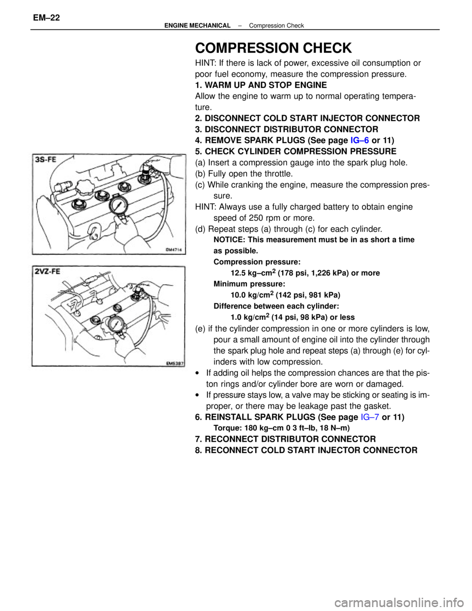
COMPRESSION CHECK
HINT: If there is lack of power, excessive oil consumption or
poor fuel economy, measure the compression pressure.
1. WARM UP AND STOP ENGINE
Allow the engine to warm up to normal operating tempera-
ture.
2. DISCONNECT COLD START INJECTOR CONNECTOR
3. DISCONNECT DISTRIBUTOR CONNECTOR
4. REMOVE SPARK PLUGS (See page IG±6 or 11)
5. CHECK CYLINDER COMPRESSION PRESSURE
(a) Insert a compression gauge into the spark plug hole.
(b) Fully open the throttle.
(c) While cranking the engine, measure the compression pres-
sure.
HINT: Always use a fully charged battery to obtain engine
speed of 250 rpm or more.
(d) Repeat steps (a) through (c) for each cylinder.
NOTICE: This measurement must be in as short a time
as possible.
Compression pressure:
12.5 kg±cm
2 (178 psi, 1,226 kPa) or more
Minimum pressure:
10.0 kg/cm
2 (142 psi, 981 kPa)
Difference between each cylinder:
1.0 kg/cm
2 (14 psi, 98 kPa) or less
(e) if the cylinder compression in one or more cylinders is low,
pour a small amount of engine oil into the cylinder through
the spark plug hole and repeat steps (a) through (e) for cyl-
inders with low compression.
wIf adding oil helps the compression chances are that the pis-
ton rings and/or cylinder bore are worn or damaged.
wIf pressure stays low, a valve may be sticking or seating is im-
proper, or there may be leakage past the gasket.
6. REINSTALL SPARK PLUGS (See page IG±7 or 11)
Torque: 180 kg±cm 0 3 ft±Ib, 18 N±m)
7. RECONNECT DISTRIBUTOR CONNECTOR
8. RECONNECT COLD START INJECTOR CONNECTOR
± ENGINE MECHANICALCompression CheckEM±22
Page 1204 of 2389
INSPECTION OF TIMING BELT COMPONENTS
1. INSPECT TIMING BELT
NOTICE:
wDo not bend, twist or turn the timing belt inside out.
wDo not allow the timing belt to come into contact with
oil, water or steam.
wDo not utilize timing belt tension when installing or
removing the mount bolt of the camshaft timing pulley.
If there are any defects as shown in the figures, check
the following points:
(a) Premature parting
wCheck for proper installation.
wCheck the timing cover gasket for damage and proper
installation. 21. REMOVE CRANKSHAFT TIMING PULLEY
If the pulley cannot be removed by hand, use two screwdriv-
ers.
HINT: Position shop rags as shown to prevent damage.
22. REMOVE OIL PUMP PULLEY
Using SST, remove the nut and pulley.
SST 09616±30011
(b) If the belt teeth are cracked or damaged, check to see
if either the camshaft, water pump is locked.
EM3338
± ENGINE MECHANICALTiming Belt (3S±FE)EM±27
Page 1206 of 2389

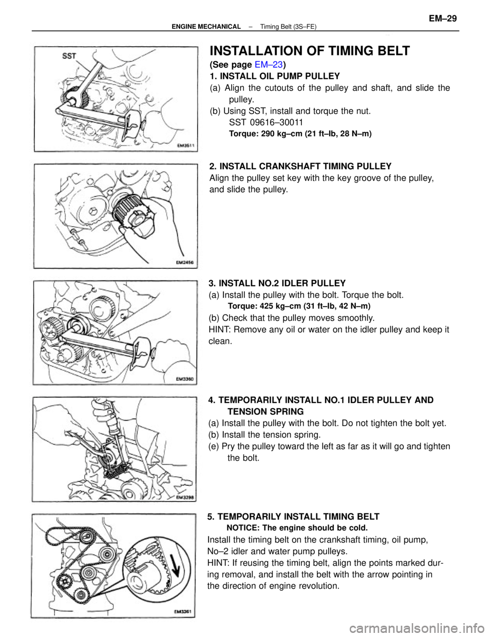
INSTALLATION OF TIMING BELT
(See page EM±23)
1. INSTALL OIL PUMP PULLEY
(a) Align the cutouts of the pulley and shaft, and slide the
pulley.
(b) Using SST, install and torque the nut.
SST 09616±30011
Torque: 290 kg±cm (21 ft±Ib, 28 N±m)
4. TEMPORARILY INSTALL NO.1 IDLER PULLEY AND
TENSION SPRING
(a) Install the pulley with the bolt. Do not tighten the bolt yet.
(b) Install the tension spring.
(e) Pry the pulley toward the left as far as it will go and tighten
the bolt.
5. TEMPORARILY INSTALL TIMING BELT
NOTICE: The engine should be cold.
Install the timing belt on the crankshaft timing, oil pump,
No±2 idler and water pump pulleys.
HINT: If reusing the timing belt, align the points marked dur-
ing removal, and install the belt with the arrow pointing in
the direction of engine revolution.3. INSTALL NO.2 IDLER PULLEY
(a) Install the pulley with the bolt. Torque the bolt.
Torque: 425 kg±cm (31 ft±Ib, 42 N±m)
(b) Check that the pulley moves smoothly.
HINT: Remove any oil or water on the idler pulley and keep it
clean.2. INSTALL CRANKSHAFT TIMING PULLEY
Align the pulley set key with the key groove of the pulley,
and slide the pulley.
± ENGINE MECHANICALTiming Belt (3S±FE)EM±29
Page 1211 of 2389
REMOVAL OF TIMING BELT
1. DISCONNECT CABLE FROM NEGATIVE TERMINAL
OF BATTERY
2. (w/ CRUISE CONTROL SYSTEM)
REMOVE CRUISE CONTROL ACTUATOR AND
VACUUM PUMP
(See step 14 on page EM±140 or 141)
3. REMOVE PS OIL RESERVOIR TANK WITHOUT
DISCONNECTING HOSES
(See step 35 on page EM±144)
4. REMOVE RH FRONT WHEEL
5. REMOVE ALTERNATOR DRIVE BELT
6. REMOVE RH FENDER APRON SEAL
7. REMOVE PS DRIVE BELT
TIMING BELT (2VZ±FE)
COMPONENTS
± ENGINE MECHANICALTiming Belt (2VZ±FE)EM±34
Page 1212 of 2389

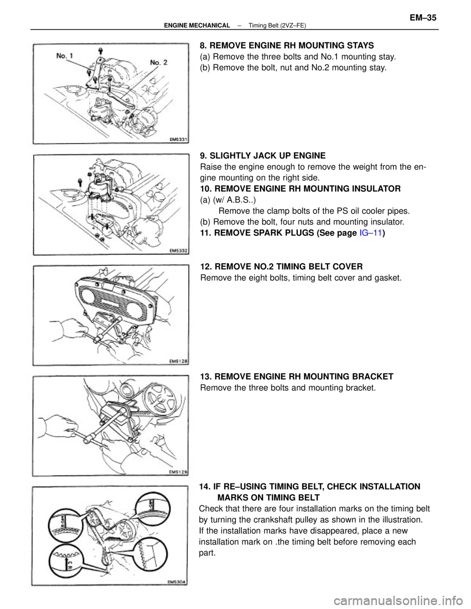
9. SLIGHTLY JACK UP ENGINE
Raise the engine enough to remove the weight from the en-
gine mounting on the right side.
10. REMOVE ENGINE RH MOUNTING INSULATOR
(a) (w/ A.B.S..)
Remove the clamp bolts of the PS oil cooler pipes.
(b) Remove the bolt, four nuts and mounting insulator.
11. REMOVE SPARK PLUGS (See page IG±11)
14. IF RE±USING TIMING BELT, CHECK INSTALLATION
MARKS ON TIMING BELT
Check that there are four installation marks on the timing belt
by turning the crankshaft pulley as shown in the illustration.
If the installation marks have disappeared, place a new
installation mark on .the timing belt before removing each
part.8. REMOVE ENGINE RH MOUNTING STAYS
(a) Remove the three bolts and No.1 mounting stay.
(b) Remove the bolt, nut and No.2 mounting stay.
12. REMOVE NO.2 TIMING BELT COVER
Remove the eight bolts, timing belt cover and gasket.
13. REMOVE ENGINE RH MOUNTING BRACKET
Remove the three bolts and mounting bracket.
± ENGINE MECHANICALTiming Belt (2VZ±FE)EM±35
Page 1217 of 2389
INSPECTION OF TIMING BELT
COMPONENTS
1. INSPECT TIMING BELT
NOTICE:
wDo not bend, twist or turn the timing belt inside out.
wDo not allow the timing belt to come into contact
with oil, water or steam.
wDo not utilize timing belt tension when installing or removing
the mount bolt of the camshaft timing pulley.
If there are any defects as shown in the figures, check the
following points:
(a) Premature parting
wCheck for proper installation.
wCheck the timing cover gasket for damage and proper instal-
lation.
(c) If there are cracks or noticeable wear on the belt face,
check to see if there are nicks on the side of the idler
pulley lock and water pump.
(d) If there is wear or damage on only one side of the belt,
check the belt guide 'and the alignment of each
pulley. (b) If the belt teeth are cracked or damaged, check to see
if either camshaft is locked.
± ENGINE MECHANICALTiming Belt (2VZ±FE)EM±40
Page 1218 of 2389
3. INSPECT TIMING BELT TENSIONER
(a) Visually check tensioner for oil leakage.
HINT: If there is only the faintest trace of oil on the seal on
the push rod side, the tensioner is all right.
If leakage is found, replace the tensioner. (e) If there is noticeable wear on the belt teeth, check tim-
ing cover for damage and check for correct gasket
installation. Check for foreign material on the pulley
teeth.
If necessary, replace the timing belt.
(c) Measure the protrusion of the push rod from the hous-
ing end.
Protrusion: 10.5 ± 11.5 mm (0.413 ± 0.453 in.)
If the protrusion is not as specified, replace the ten-
sioner. (b) Hold the tensioner with both hands and push the push
rod strongly against the floor or wall to check that it
doesn't move.
If the push rod moves, replace the tensioner. 2. INSPECT IDLER PULLEYS
Check the turning smoothness of the idler pulley.
If necessary, replace the idler pulley.
± ENGINE MECHANICALTiming Belt (2VZ±FE)EM±41
Page 1219 of 2389

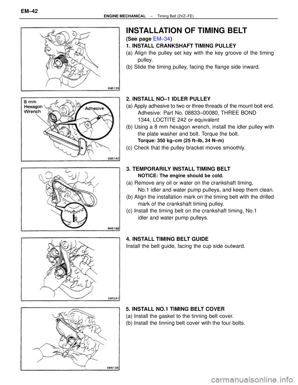
2. INSTALL NO±1 IDLER PULLEY
(a) Apply adhesive to two or three threads of the mount bolt end.
Adhesive: Part No. 08833±00080, THREE BOND
1344, LOCTITE 242 or equivalent
(b) Using a 8 mm hexagon wrench, install the idler pulley with
the plate washer and bolt. Torque the bolt.
Torque: 350 kg±cm (25 ft±Ib, 34 N±m)
(c) Check that the pulley bracket moves smoothly.
3. TEMPORARILY INSTALL TIMING BELT
NOTICE: The engine should be cold.
(a) Remove any oil or water on the crankshaft timing,
No.1 idler and water pump pulleys, and keep them clean.
(b) Align the installation mark on the timing belt with the drilled
mark of the crankshaft timing pulley.
(c) Install the timing belt on the crankshaft timing, No.1
idler and water pump pulleys.
INSTALLATION OF TIMING BELT
(See page EM±34)
1. INSTALL CRANKSHAFT TIMING PULLEY
(a) Align the pulley set key with the key groove of the timing
pulley.
(b) Slide the timing pulley, facing the flange side inward.
5. INSTALL NO.1 TIMING BELT COVER
(a) Install the gasket to the tinning belt cover.
(b) Install the tinning belt cover with the four bolts.4. INSTALL TIMING BELT GUIDE
Install the belt guide, facing the cup side outward.
± ENGINE MECHANICALTiming Belt (2VZ±FE)EM±42