Page 1249 of 2389
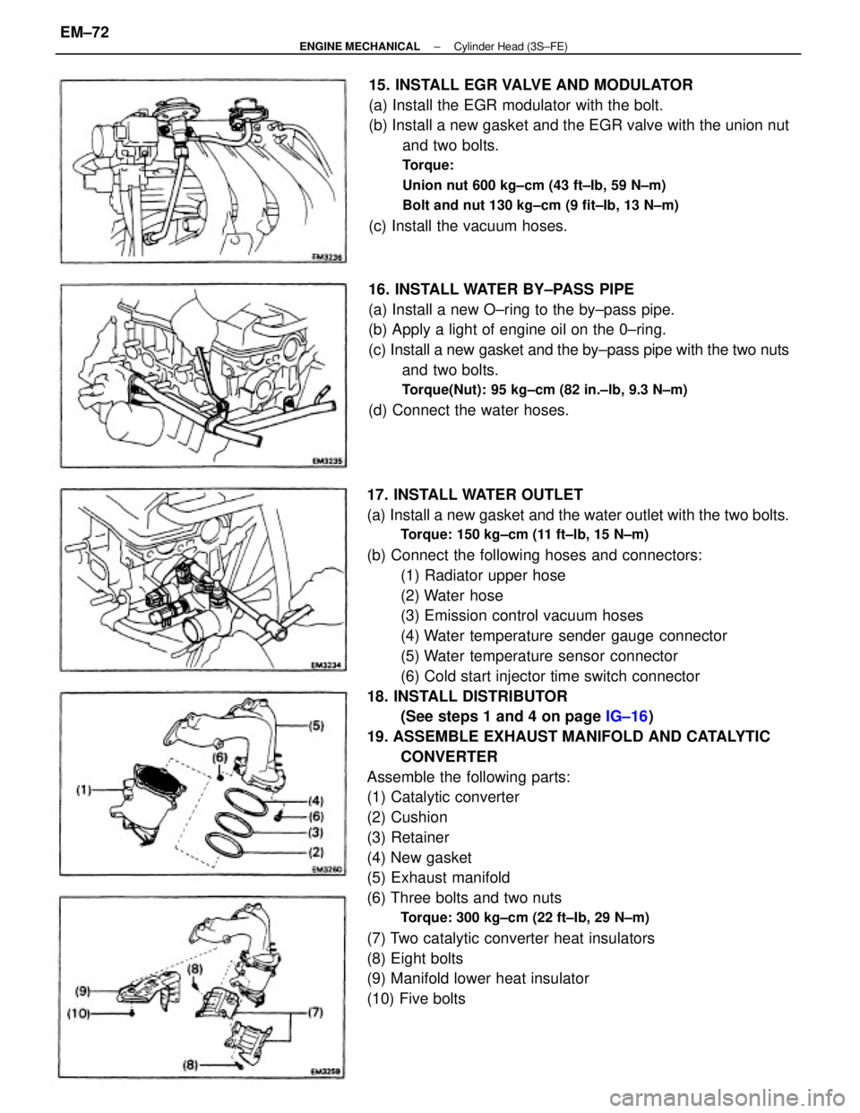
17. INSTALL WATER OUTLET
(a) Install a new gasket and the water outlet with the two bolts.
Torque: 150 kg±cm (11 ft±lb, 15 N±m)
(b) Connect the following hoses and connectors:
(1) Radiator upper hose
(2) Water hose
(3) Emission control vacuum hoses
(4) Water temperature sender gauge connector
(5) Water temperature sensor connector
(6) Cold start injector time switch connector
18. INSTALL DISTRIBUTOR
(See steps 1 and 4 on page IG±16)
19. ASSEMBLE EXHAUST MANIFOLD AND CATALYTIC
CONVERTER
Assemble the following parts:
(1) Catalytic converter
(2) Cushion
(3) Retainer
(4) New gasket
(5) Exhaust manifold
(6) Three bolts and two nuts
Torque: 300 kg±cm (22 ft±Ib, 29 N±m)
(7) Two catalytic converter heat insulators
(8) Eight bolts
(9) Manifold lower heat insulator
(10) Five bolts15. INSTALL EGR VALVE AND MODULATOR
(a) Install the EGR modulator with the bolt.
(b) Install a new gasket and the EGR valve with the union nut
and two bolts.
Torque:
Union nut 600 kg±cm (43 ft±Ib, 59 N±m)
Bolt and nut 130 kg±cm (9 fit±Ib, 13 N±m)
(c) Install the vacuum hoses.
16. INSTALL WATER BY±PASS PIPE
(a) Install a new O±ring to the by±pass pipe.
(b) Apply a light of engine oil on the 0±ring.
(c) Install a new gasket and the by±pass pipe with the two nuts
and two bolts.
Torque(Nut): 95 kg±cm (82 in.±lb, 9.3 N±m)
(d) Connect the water hoses.
± ENGINE MECHANICALCylinder Head (3S±FE)EM±72
Page 1251 of 2389
26. INSTALL OIL PRESSURE SWITCH, ENGINE HANGERS
AND ALTERNATOR BRACKET
Torque the bolts.
Torque: 500 kg±cm (37 ft±Ib, 48 N±m)
27. INSTALL ALTERNATOR (See page CH±14)
28. INSTALL AIR CLEANER HOSE
29. INSTALL CRUISE CONTROL ACTUATOR
(See step 26 on page EM±137)
30. INSTALL RADIATOR RESERVOIR TANK
31. INSTALL ACCELERATOR CABLE, AND ADJUST IT
32. (A/T)
CONNECT THROTTLE CABLE, AND ADJUST IT
33. FILL WITH ENGINE COOLANT (See page CO±5)
Capacity (w/ Heater):
M/T 6.4 liters (6.8 US qts, 5.6 Imp. qts)
A/T (2WD) 6.3 liters (6.7 US qts, 5.5 Imp. qts)
A/T (4WD) 6.8 liters (7.2 US qts, 6.0 Imp. qts)
34. CONNECT CABLE TO NEGATIVE TERMINAL OF
BATTERY
35. START ENGINE AND CHECK FOR LEAKS
36. PERFORM ENGINE ADJUSTMENT
(a) Adjust the valve clearance. (See page EM±11)
Valve clearance (Cold):
Intake 0.19 ± 0.29 mm (0.007 ± 0.011 in.)
Exhaust 0.28 ± 0.38 mm (0.011 ± 0.015 in.)
(b) Adjust the ignition timing.
(See steps 7 to 10 on pages IG±16 and 17)
Ignition timing:
10° BTDC @ idle
(w/ Terminals TE 1 and E 1 connected)
37. CHECK TOE±IN (See page FA±5)
38. PERFORM ROAD TEST
Check for abnormal noise, shock, slippage, correct shift
points and smooth operation.
39. RECHECK ENGINE COOLANT LEVEL AND OIL LEVEL
± ENGINE MECHANICALCylinder Head (3S±FE)EM±74
Page 1256 of 2389
31. REMOVE NO.3 TIMING BELT COVER
Remove the six bolts and timing belt cover.
NOTICE:
wSupport the belt so the meshing of the crankshaft
timing pulley and timing belt does not shift.
wBe careful not to drop anything inside the timing belt cover.
wDo not allow the belt to come into contact with oil, water or
dust. (b) Remove the six nuts, exhaust manifold and gasket.
29. REMOVE SPARK PLUGS (See page IG±11)
30. REMOVE TIMING BELT, CAMSHAFT TIMING
PULLEYS AND No.2 IDLER PULLEY
(See steps 3 to 19 on pages EM±34 to 37) 28. REMOVE LH EXHAUST MANIFOLD
(a) Remove the two nuts and heat insulator. (c) Remove the six nuts, exhaust manifold and gasket.
(d) Remove the bolt and inside heat insulator.
± ENGINE MECHANICALCylinder Heads (2VZ±FE)EM±79
Page 1258 of 2389
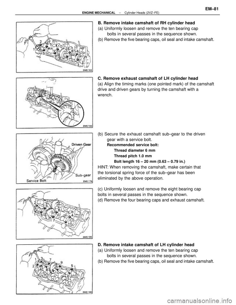
(b) Secure the exhaust camshaft sub±gear to the driven
gear with a service bolt.
Recommended service bolt:
Thread diameter 6 mm
Thread pitch 1.0 mm
Bolt length 16 ± 20 mm (0.63 ± 0.79 in.)
HINT: When removing the camshaft, make certain that
the torsional spring force of the sub±gear has been
eliminated by the above operation.
D. Remove intake camshaft of LH cylinder head
(a) Uniformly loosen and remove the ten bearing cap
bolts in several passes in the sequence shown.
(b) Remove the five bearing caps, oil seal and intake camshaft.B. Remove intake camshaft of RH cylinder head
(a) Uniformly loosen and remove the ten bearing cap
bolts in several passes in the sequence shown.
(b) Remove the five bearing caps, oil seal and intake camshaft.
C. Remove exhaust camshaft of LH cylinder head
(a) Align the timing marks (one pointed mark) of the camshaft
drive and driven gears by turning the camshaft with a
wrench.
(c) Uniformly loosen and remove the eight bearing cap
bolts in several passes in the sequence shown.
(d) Remove the four bearing caps and exhaust camshaft.
± ENGINE MECHANICALCylinder Heads (2VZ±FE)EM±81
Page 1261 of 2389
2. REMOVE VALVES
(a) Using SST, compress the valve spring and remove the two
keepers.
SST 09202±70010
(b) Remove the spring retainer, valve spring, valve and spring
seat.
DISASSEMBLY OF CYLINDER HEADS
(See page EM±75)
1 . REMOVE VALVE LIFTERS AND SHIMS
HINT: Arrange the valves, valve springs, spring seats
and spring retainers in correct order.
(c) Using needle±nose pliers, remove the oil seal. HINT: Arrange the valve lifters and shims in correct or-
der.
± ENGINE MECHANICALCylinder Heads (2VZ±FE)EM±84
Page 1262 of 2389
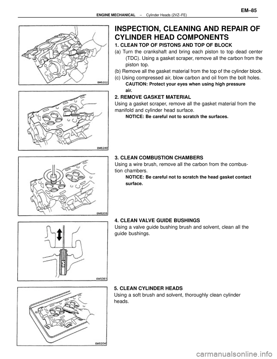
INSPECTION, CLEANING AND REPAIR OF
CYLINDER HEAD COMPONENTS
1. CLEAN TOP OF PISTONS AND TOP OF BLOCK
(a) Turn the crankshaft and bring each piston to top dead center
(TDC). Using a gasket scraper, remove all the carbon from the
piston top.
(b) Remove all the gasket material from the top of the cylinder block.
(c) Using compressed air, blow carbon and oil from the bolt holes.
CAUTION: Protect your eyes when using high pressure
air.
2. REMOVE GASKET MATERIAL
Using a gasket scraper, remove all the gasket material from the
manifold and cylinder head surface.
NOTICE: Be careful not to scratch the surfaces.
3. CLEAN COMBUSTION CHAMBERS
Using a wire brush, remove all the carbon from the combus-
tion chambers.
NOTICE: Be careful not to scratch the head gasket contact
surface.
4. CLEAN VALVE GUIDE BUSHINGS
Using a valve guide bushing brush and solvent, clean all the
guide bushings.
5. CLEAN CYLINDER HEADS
Using a soft brush and solvent, thoroughly clean cylinder
heads.
± ENGINE MECHANICALCylinder Heads (2VZ±FE)EM±85
Page 1264 of 2389
(b) Using a micrometer, measure the diameter of the valve
stem.
Valve stem diameter:
Intake 5.970 ± 5.985 mm
(0.2350 ± 0.2356 in.)
Exhaust 5.965 ± 5.980 mm
(0.2348 ± 0.2354 in.)
(c) Subtract the valve stem diameter measurement from
the guide bushing inside diameter measurement.
Standard oil clearance:
Intake 0.025 ± 0.060 mm
(0.0010 ± 0.0024 in.)
Exhaust 0.030 ± 0.065 mm
(0.0012 ± 0.0026 in.)
Maximum oil clearance:
Intake 0.08 mm (0.0031 in.)
Exhaust 0.10 mm (0.0039 in.)
If the clearance is greater than maximum, replace the
valve and guide bushing.
10. IF NECESSARY, REPLACE VALVE GUIDE BUSHINGS
(a) Insert an old valve wrapped with tape into the valve
guide bushing, and break off the valve guide bushing by
hitting it with a hammer.
NOTICE: Be careful not to damage the valve lifter hole.
(c) Using SST and a hammer, tap out the guide bushing.
SST 09201± 70010 (b) Gradually heat the cylinder head to 80 ±100
°C (176
± 212°F).
± ENGINE MECHANICALCylinder Heads (2VZ±FE)EM±87
Page 1268 of 2389
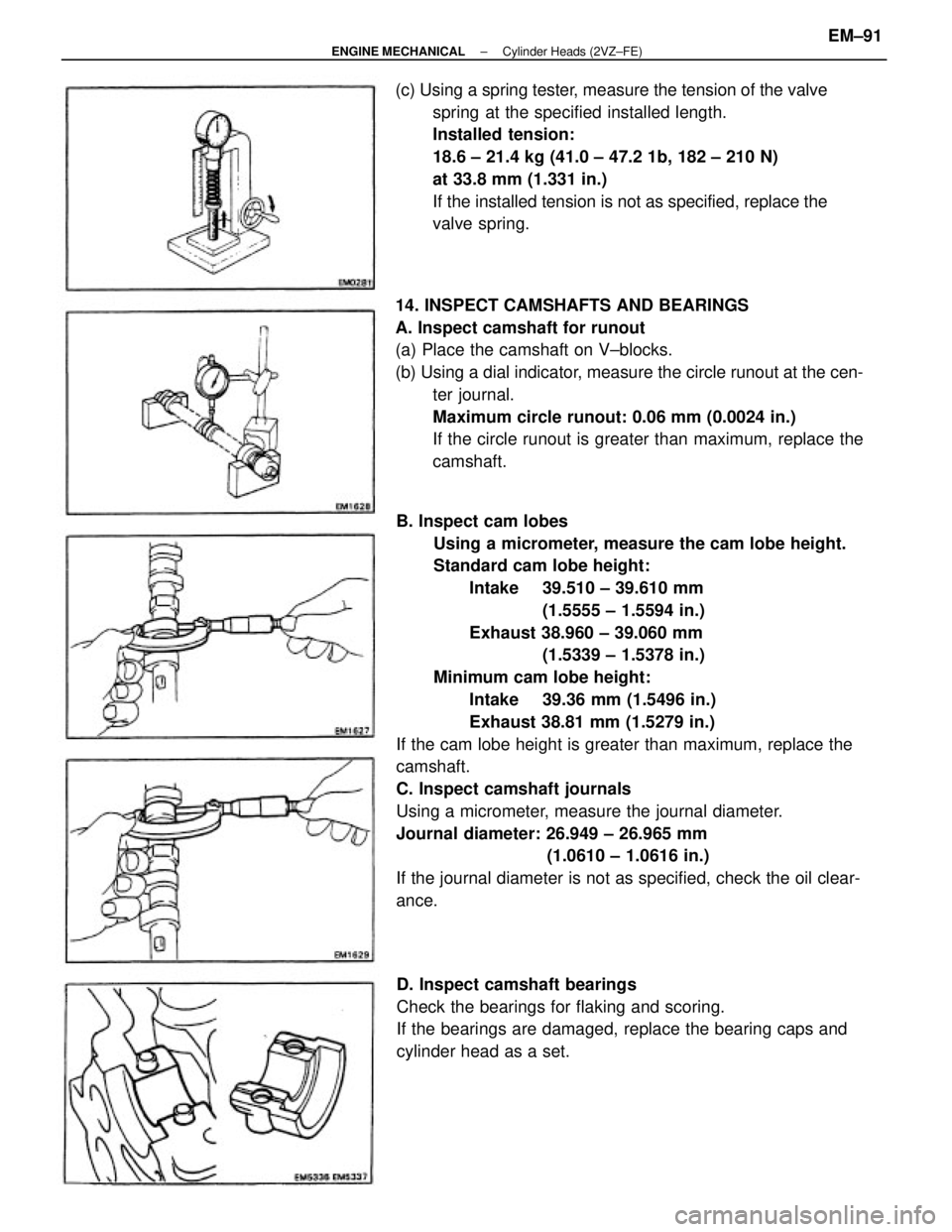
B. Inspect cam lobes
Using a micrometer, measure the cam lobe height.
Standard cam lobe height:
Intake 39.510 ± 39.610 mm
(1.5555 ± 1.5594 in.)
Exhaust 38.960 ± 39.060 mm
(1.5339 ± 1.5378 in.)
Minimum cam lobe height:
Intake 39.36 mm (1.5496 in.)
Exhaust 38.81 mm (1.5279 in.)
If the cam lobe height is greater than maximum, replace the
camshaft.
C. Inspect camshaft journals
Using a micrometer, measure the journal diameter.
Journal diameter: 26.949 ± 26.965 mm
(1.0610 ± 1.0616 in.)
If the journal diameter is not as specified, check the oil clear-
ance. 14. INSPECT CAMSHAFTS AND BEARINGS
A. Inspect camshaft for runout
(a) Place the camshaft on V±blocks.
(b) Using a dial indicator, measure the circle runout at the cen-
ter journal.
Maximum circle runout: 0.06 mm (0.0024 in.)
If the circle runout is greater than maximum, replace the
camshaft. (c) Using a spring tester, measure the tension of the valve
spring at the specified installed length.
Installed tension:
18.6 ± 21.4 kg (41.0 ± 47.2 1b, 182 ± 210 N)
at 33.8 mm (1.331 in.)
If the installed tension is not as specified, replace the
valve spring.
D. Inspect camshaft bearings
Check the bearings for flaking and scoring.
If the bearings are damaged, replace the bearing caps and
cylinder head as a set.
± ENGINE MECHANICALCylinder Heads (2VZ±FE)EM±91