1973 DATSUN B110 transmission oil
[x] Cancel search: transmission oilPage 331 of 513

ENGINE
Spark
plugs
Cap
mm
in
0
8
to
0
9
0
03110
0
035
Idle
CO
ldie
speed
Manual
transmission
rpm
rpm
1
5
to
5
800
1
5
to
5
650
in
D
position
Automatic
transmission
Dash
pot
Setting
engine
speed
rpm
1
900
to
2
000
Throttle
opener
at
sea
level
Setting
vacuwn
pressure
Manual
transmission
Automatic
transmission
Setting
engine
speed
no
load
Servo
diaphragm
full
stroke
rpm
mm
in
500
to
540
19
7
to
21
3
480
to
520
18
9
to
20
5
1
650
to
1
850
5
0
1969
mmHg
in
Hg
mmHg
in
Hg
Theono
switch
Temperature
rises
from
low
to
high
oC
0
F
above
5
41
Flow
guide
valve
Opera
ting
pressure
mmHg
in
Hg
10
0
4
TROUBLE
DIAGNOSES
AND
CORRECTIONS
Troubles
Possible
causes
Remedies
CANNOT
CRANK
ENGINE
OR
SLOW
CRANKING
Improper
grade
oiL
Replace
with
proper
grade
oiL
Discharged
battery
Charge
battery
Defective
battery
Replace
Loosen
fan
belt
Adjust
Trouble
in
charge
system
Inspect
charge
system
Wiring
connection
trouble
in
starting
circuit
Correct
Defective
starter
switch
Repair
or
replace
Defective
starter
motor
Repair
or
replace
ET
26
I
Page 373 of 513

ENGINE
MECHANICAL
SERVICE
DATA
AND
SPECIFICATIONS
GENERAL
SPECIFICATION
Cylinder
arrangement
4
in
line
Displacement
cc
cu
in
mm
in
1
171
71
5
73
x
70
2
874
x
2
756
Bore
and
stroke
Valve
arrangemen
t
Over
head
valve
Firing
order
I
3
4
2
Engine
idle
rpm
800
Manual
transmission
650in
D
Automatic
transmission
Compression
ratio
8
5
Oil
pressure
Hot
at
2
000
rpm
kgfcm2
Ibfsq
in
3
0
to
3
5
43
to
50
TIGHTENING
TORQUE
Unit
kg
m
ft
lb
Cylinder
head
bolts
Flywheel
bolts
5
5
to
6
0
40
to
43
3
2
to
3
8
23
to
28
6
5
to
7
5
47
to
54
5
0
to
6
0
36
to
43
4
0
to
4
8
29
to
35
0
4
to
0
6
2
9
to
4
3
l
l
to
I
7
8
0
to
12
0
9
to
I
4
6
5
to
10
15
to
16
108
to
116
Connecting
rod
nuts
Main
bearing
cap
bolts
Camshaft
gear
bolts
Oil
pan
bolts
Oil
pump
bolts
Oil
strainer
bolts
Crank
pulley
bolts
EM
33
Page 488 of 513
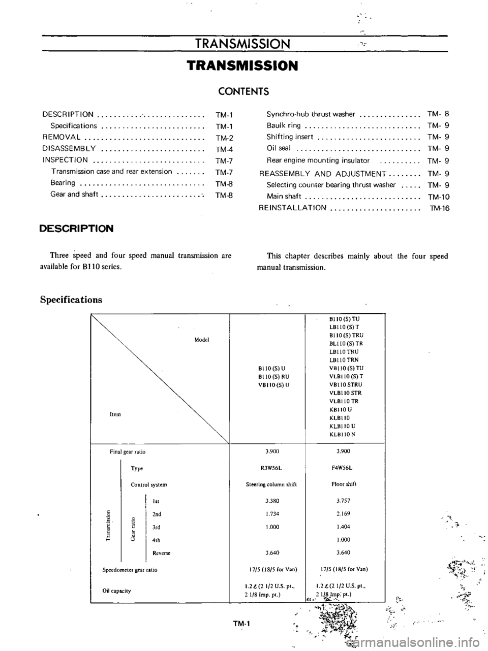
TRANSMISSION
TRANSMISSION
CONTENTS
DESCRIPTION
Specifications
REMOVAL
DISASSEMBLY
INSPECTION
Transmission
case
and
rear
extension
Bearing
Gear
and
shaft
TM
l
TM
l
TM
2
TM
4
TM
7
TM
7
TM
8
TM
8
DESCRIPTION
Three
speed
and
four
speed
manual
transmission
are
available
for
BJ
10
series
Specifications
Model
Item
Finalgear
atio
Type
Control
ystem
nd
J
d
4th
Rever
Speedometer
gear
aHo
Oil
apacity
TM
8
TM
9
TM
9
TM
9
TM
9
TM
9
TM
9
TM
l0
TM
16
Synchro
hub
thrust
washer
Baulk
ring
Shilting
insert
Oil
seal
Rear
engine
mounting
insulator
REASSEMBLY
AND
ADJUSTMENT
Selecting
counter
bearing
thrust
washer
Main
shaft
REINSTALLATION
This
chapter
describes
mainly
about
the
four
speed
manual
transmission
811O
5
U
8110
5
RU
VBIIO
S
U
3
900
R3W56L
Steering
olumn
shift
3
380
1
734
1
000
3
640
17
5
18
5
for
Van
I
2l
2
1
2
U
S
pl
1
8
Imp
pc
TM
l
BIIO
S
TU
LB110
S
T
BllO
5
TRU
DUlO
5
TR
L8110
TRU
L8110
TRN
VBllO
S
TU
VLBllO
5
T
VBllO
SIRU
VLBllO
SIR
VLBllO
TR
KBIIO
U
KLBllO
KLBllO
U
KLBI
O
N
3
900
F4W56L
Floor
shift
3
757
69
1
404
1
000
3
640
17
5
18
5
for
Van
i
r
i
1
2
t
2
1
2
U
S
pt
IJ8Imp
pt
l
OC
t
1
I
t
y
y
dt
k
J
t
i
r
Page 490 of 513
TRANSMISSION
I
Jack
up
the
vehicle
and
support
it
with
four
stands
If
available
recommend
a
hydraulic
hoist
or
open
pit
be
utilized
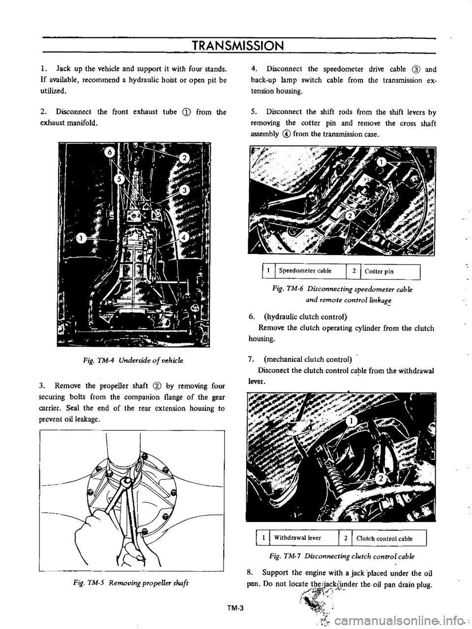
2
Disconnect
the
front
exhaust
tube
D
from
the
exhaust
manifold
Fig
TM
4
Underside
of
vehiJ
1e
3
Remove
the
propeller
shaft
@
by
removing
four
securing
bolts
from
the
companion
flange
of
the
gear
carrier
Seal
the
end
of
the
rear
extension
housing
to
prevent
oil
leakage
Fig
TM
5
Removing
propeller
haft
4
Disconnect
the
speedometer
drive
cable
ID
and
back
up
lamp
switch
cable
from
the
transmission
ex
tension
housing
s
Disconnect
the
shift
rods
from
the
shift
levers
by
removing
the
cotter
pin
and
remove
the
cross
shaft
assembly
@
from
the
transmission
case
r
J
f
f
1
I
Speedometer
cable
I
2
I
Cotter
pin
Fig
TM
6
Disconnecting
speedometer
cable
and
remote
controllinkag
6
hydraulic
clutch
control
Remove
the
clutch
operating
cylinder
from
the
clutch
housing
7
mechanical
clutch
control
Disconect
the
clutch
control
cable
from
the
withdrawal
lever
1
1
Withdrawal
lever
2
I
Clutch
control
cable
Fig
TM
7
Disconnecting
clutch
control
cable
8
Support
the
engine
with
ajack
placed
under
the
oil
pan
Do
not
loca
1
f
nder
the
oil
pan
drain
plug
I
i
l
TM
3
Page 491 of 513
CHASSIS
To
prevent
the
oil
pan
from
damaging
insert
a
wooden
block
between
the
pan
and
jack
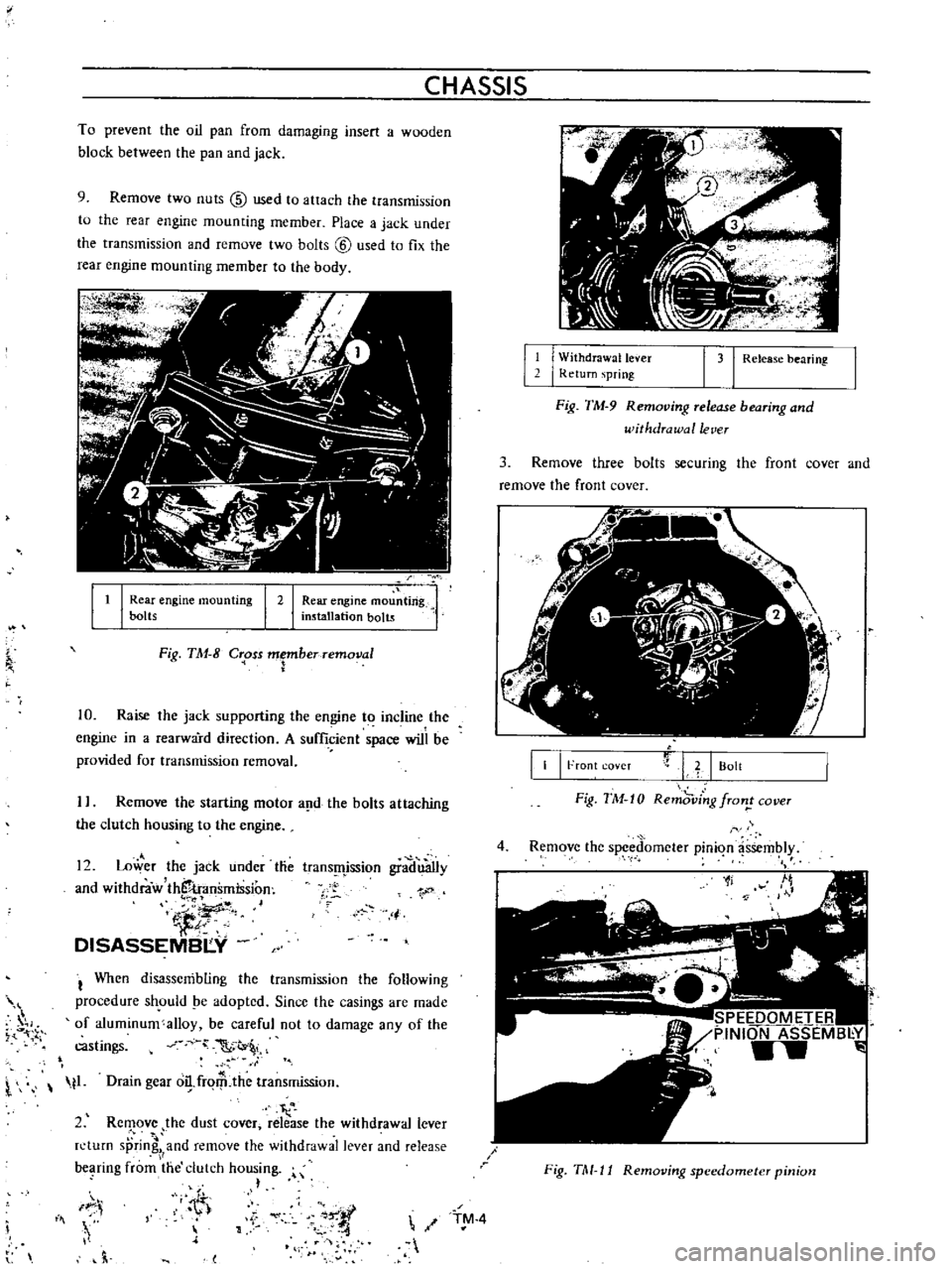
9
Remove
two
nuts
@
used
to
attach
the
transmission
to
the
rear
engine
mounting
member
Place
a
jack
under
the
transmission
and
remove
two
bolts
@
used
to
fix
the
rear
engine
mounting
member
to
the
body
It
I
Rear
engine
mou
ting
installation
bolts
I
Rear
engine
mounting
bolts
I
2
Fig
TM
8
C
oss
Fberremoval
10
Raise
the
jack
supporting
the
engine
to
incline
the
engine
in
a
rearward
direction
A
sufficient
space
will
be
provided
for
transmission
removal
I
Remove
the
starting
motor
a
d
the
bolts
attaching
the
clutch
housing
to
the
engine
12
Lower
the
jack
under
tlie
and
withdraw
thS
transmission
iJ
DISASSEMBI
Y
trans
fljssion
gradu3Ily
1
j
I
When
disassembling
the
transmission
the
following
procedure
sh
ould
pe
adopted
Since
the
casings
are
made
of
aluminum
alloy
be
careful
not
to
damage
any
of
the
castings
C
t
l
t1
Drain
gear
o
frqrP
the
transmission
I
2
Rc
ove
the
dust
cover
release
the
withdrawal
lever
n
turn
sprin
and
remove
the
withdrawal
lever
and
release
bC
lring
from
the
clutch
housing
h
IF
i
Iii
h
l
11
I
W
ithdrawallever
I
Return
spring
1
31
Release
bearing
Fig
TM
9
Removing
release
bearing
and
withdrawal
lever
3
Remove
three
bolts
securing
the
front
cover
and
remove
the
front
cover
II
I
Front
coveT
L
I
Bolt
Fig
TM
10
Remd
ving
fron
cover
4
Remove
the
spced
omcter
pinion
assembly
1f
SPEEDOMETER
PINION
ASSEMB
Y
w
Fig
TM
11
Removing
speedometer
pinion
TM
4
Page 494 of 513
TRANSMISSION
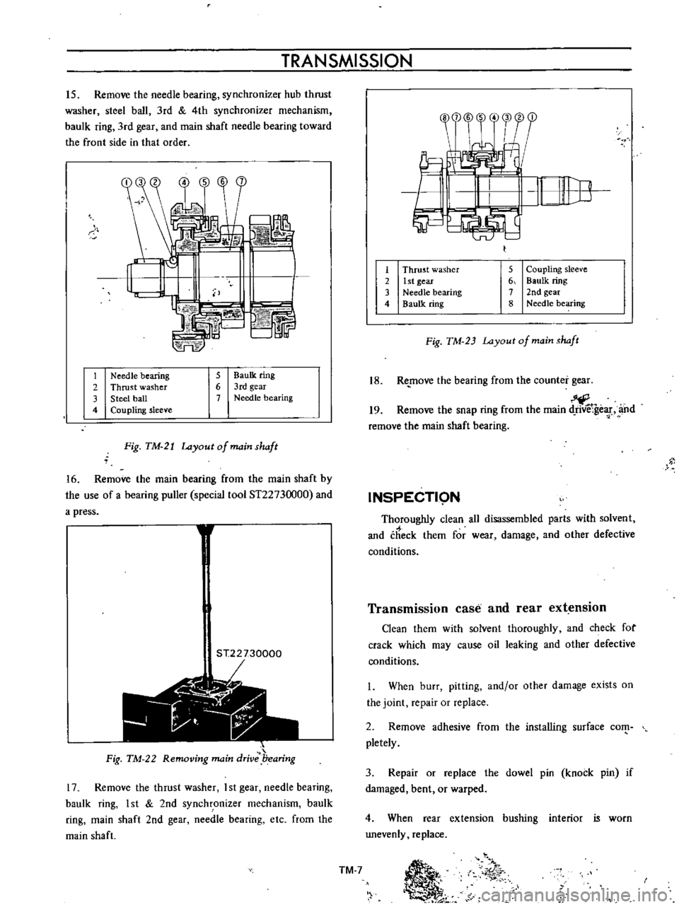
15
Remove
the
needle
bearing
synchronizer
hub
thrust
washer
steel
ball
3rd
4th
synchronizer
mechanism
baulk
ring
3rd
gear
and
main
shaft
needle
bearing
toward
the
front
side
in
that
order
S
b
L
74FE
r
1
Needle
bearing
2
Thrust
washer
3
Steel
ball
4
Coupling
sleeve
5
BauIk
ring
6
3rd
gear
7
Needle
bearing
Fig
TM
21
Layout
of
main
shaft
16
Remove
the
main
bearing
from
the
main
shaft
by
the
use
of
a
bearing
puller
special
tool
ST2273
000
and
a
press
1
ST22730000
r
1
t
Jii
Fig
TM
22
Removing
main
drive
l7earing
17
Remove
the
thrust
washer
I
st
gear
needle
bearing
baulk
ring
1st
2nd
synchronizer
mechanism
baulk
ring
main
shaft
2nd
gear
needle
bearing
etc
from
the
main
shaft
1
2
3
4
5
Coupling
sleeve
6
Baulk
ring
7
2nd
gear
8
Needle
bearing
Thrust
washer
1st
gear
Needle
bearing
Baulk
ring
Fig
TM
23
Layout
of
main
shaft
18
Re
move
the
bearing
from
the
counter
gear
19
Remove
the
snap
ring
from
the
main
ge
f
and
remove
the
main
shaft
bearing
INSPECTI9N
Thoroughly
clean
all
disassembled
parts
with
solvent
and
check
them
for
wear
damage
and
other
defective
conditions
Transmission
case
and
rear
extension
Clean
them
with
solvent
thoroughly
and
check
for
crack
which
may
cause
oil
leaking
and
other
defective
conditions
I
When
burr
pitting
and
or
other
damage
exists
on
the
joint
repair
or
replace
2
Remove
adhesive
from
the
installing
surface
com
pletely
3
Repair
or
replace
the
dowel
pin
knock
pin
if
damaged
bent
or
warped
4
When
rear
extension
bushing
interior
is
worn
unevenly
replace
TM
7
Ii
01
r
Page 496 of 513
TR
ANSMISSION
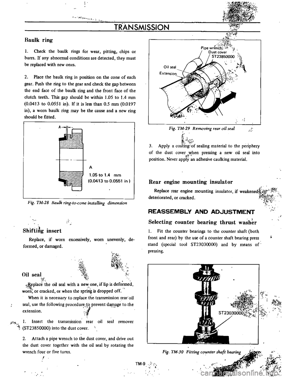
Baulk
ring
I
Check
the
baulk
rings
for
wear
pitting
chips
or
burrs
If
any
abnormal
conditions
are
detected
they
must
be
replaced
with
new
ones
2
Place
the
baulk
ring
in
position
on
the
cone
of
each
gear
Push
the
ring
to
the
gear
and
check
the
gap
between
the
end
face
of
the
bauIk
ring
and
the
front
face
of
the
clutch
teeth
This
gap
should
be
within
1
05
to
I
4
mm
0
0413
to
0
0551
in
If
it
is
less
than
0
5
mm
0
0197
in
a
worn
bauIk
ring
may
be
the
cause
and
a
new
ring
should
be
fitted
ii
V
ilillltII
l
A
1
05
to
1
4
mm
0
0413
to
0
0551
in
Fig
TM
28
ulk
ring
to
cone
installing
dimension
ShiftiAg
insert
Replace
if
worn
excessively
worn
unevenly
de
formed
or
damaged
Oil
seal
i
T
l
l
11
tT
Replace
the
oil
seal
with
a
new
one
if
lip
is
deformed
f
worn
or
cracked
or
when
the
spring
is
dropped
off
When
it
is
necessary
to
replace
the
transmission
rear
oil
seal
use
the
following
procedurecto
prevent
d
age
to
the
extension
l
1
Insert
the
transmission
rear
oil
seal
remover
ST23850000
into
the
dust
cover
2
Attach
a
pipe
wrench
to
the
dust
cover
and
drive
out
the
dust
cover
together
with
the
oil
seal
by
rotating
the
wrench
four
or
five
turns
I
Oil
seal
Extension
IJ
y
Fig
TM
29
Removing
rear
oil
seal
r
VI
1
3
Apply
a
coating
of
sealing
material
to
the
periphery
of
the
dust
cover
when
pressing
a
new
oil
seal
into
position
Never
apply
an
adhesive
caulking
material
Rear
engine
mounting
insulator
Replace
rear
engine
mounting
insulator
if
weakened
a
deteriorated
or
cracked
7i
1
rt
REASSEMBLY
AND
AD
JUSTMENT
Selecting
counter
bearing
thrust
washer
l
Fit
the
counter
bearings
to
the
counter
shaft
both
front
and
rear
by
the
use
of
a
counter
shaft
bearing
press
stand
special
tool
ST23030000
and
by
means
of
pressing
r
j
Itf
Fig
TM
JO
Fitting
counter
shaft
bearing
r
JJff
i
it
l
t
i
j
IlK
Ji
t
l
k
TM
9
Page 497 of 513
1
i
I
iF
r
i
I
7
2
r
CHASSIS
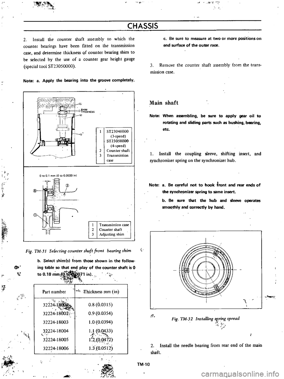
2
Install
the
counter
shaft
assembly
to
which
the
counter
bearings
have
been
fitted
on
the
transmission
case
and
determine
thickness
Qf
counter
bearing
shim
to
be
selected
by
the
use
of
a
counter
gear
height
gauge
special
tool
ST23050000
Note
a
Apply
the
bearing
into
the
groove
completely
ij
I
i
I
lyi
FIII
I
1
1
TI
t
J
I
IJt
k
u
lN
III
1
0
SHIM
PC
I
1
7
L
THICKNESS
t
ll
l
1n
J
J
2
ST23040000
3
speed
ST23050000
4
specd
Counter
shaft
Transmission
case
o
0
1
mm
0
0
0039
n
Ir
@
f
@
II
1
Transmission
case
2
Counter
shaft
3
Adjusting
shim
Fig
TM
31
Selecting
counter
slullt
front
bearing
shim
e
lZ
b
Select
shim
s
from
those
shown
in
the
follow
ing
table
so
that
end
play
of
the
counter
shaft
is
0
to
0
18
mm
O
7
1
in
f1l
ft
7
fI
1
Part
number
lli
ifhickness
mm
in
32224
1
32224
18002
32224
18003
32224
18004
32224
18005
32224
18006
0
8
0
0315
0
9
0
0354
1
0
0
0394
LI
0
0433
I
Uo
g
72
1
3
0
0512
I
t
c
Be
sure
to
measure
at
two
or
more
positions
on
end
surface
of
the
outer
race
3
Remove
the
counter
shaft
assembly
from
the
trans
mission
case
Main
shaft
Note
When
assembling
be
sure
to
apply
gear
oil
to
rotating
and
sliding
parts
such
as
bushing
b
ring
etc
Install
the
coupling
sleeve
shifting
insert
and
synchronizer
spring
on
the
synchronizer
hub
Note
a
Be
careful
not
to
hook
front
and
rear
ends
of
the
synchronizer
spring
to
same
insert
b
Be
sure
that
the
hub
and
sleeve
operates
smoothly
and
correctly
by
hand
I
I
Fig
TM
32
Installing
sp
ring
spread
T
2
Install
the
needle
bearing
from
rear
end
of
the
main
shaft
TM
l0