Page 64 of 513

CHASSIS
SERVICE
DATA
AND
SPECIFICATIONS
General
specifications
Torque
converter
Type
Stall
torque
ratio
Transmission
Type
Control
elements
Gear
ratio
Selector
positions
Oil
pump
Type
Number
of
pump
Oil
Capacity
Hydraulic
control
system
Lubrication
system
Cooling
system
Multiple
disc
clutch
Band
brake
Multiple
disc
brake
One
way
clutch
1st
lnd
3rd
Reverse
P
Park
R
Reverse
N
Neutral
D
Drive
1
lnd
lock
I
Lock
up
AT
60
Symmetrical3
element
I
stage
l
phase
torque
converter
coupling
2
0
I
3
speed
forward
and
one
speed
reverse
with
planetary
gear
train
1
I
I
I
2
458
1
458
1
000
2
182
The
transmission
is
placed
in
neutral
The
output
shaft
is
fixed
The
engine
can
be
started
Backward
running
The
transmission
is
in
neutral
The
engine
can
be
started
Up
or
downshifts
automatically
to
and
from
1st
lnd
and
top
Fixed
at
2nd
Fixed
at
low
or
downshifts
from
2nd
Internally
intermeslting
involute
gear
pump
Automatic
transmission
fluid
Dexron
type
5
5
liters
57
8
U
S
qts
47
8
Imp
qts
Approximately
1
7
liters
27
8
U
S
qts
2
3
8
Imp
qts
in
torque
converter
Controlled
by
detecting
the
negative
pressure
of
intake
manifold
and
the
revolution
speed
of
output
shaft
Forced
lubrication
by
an
oil
pwnp
Air
cooled
Page 66 of 513

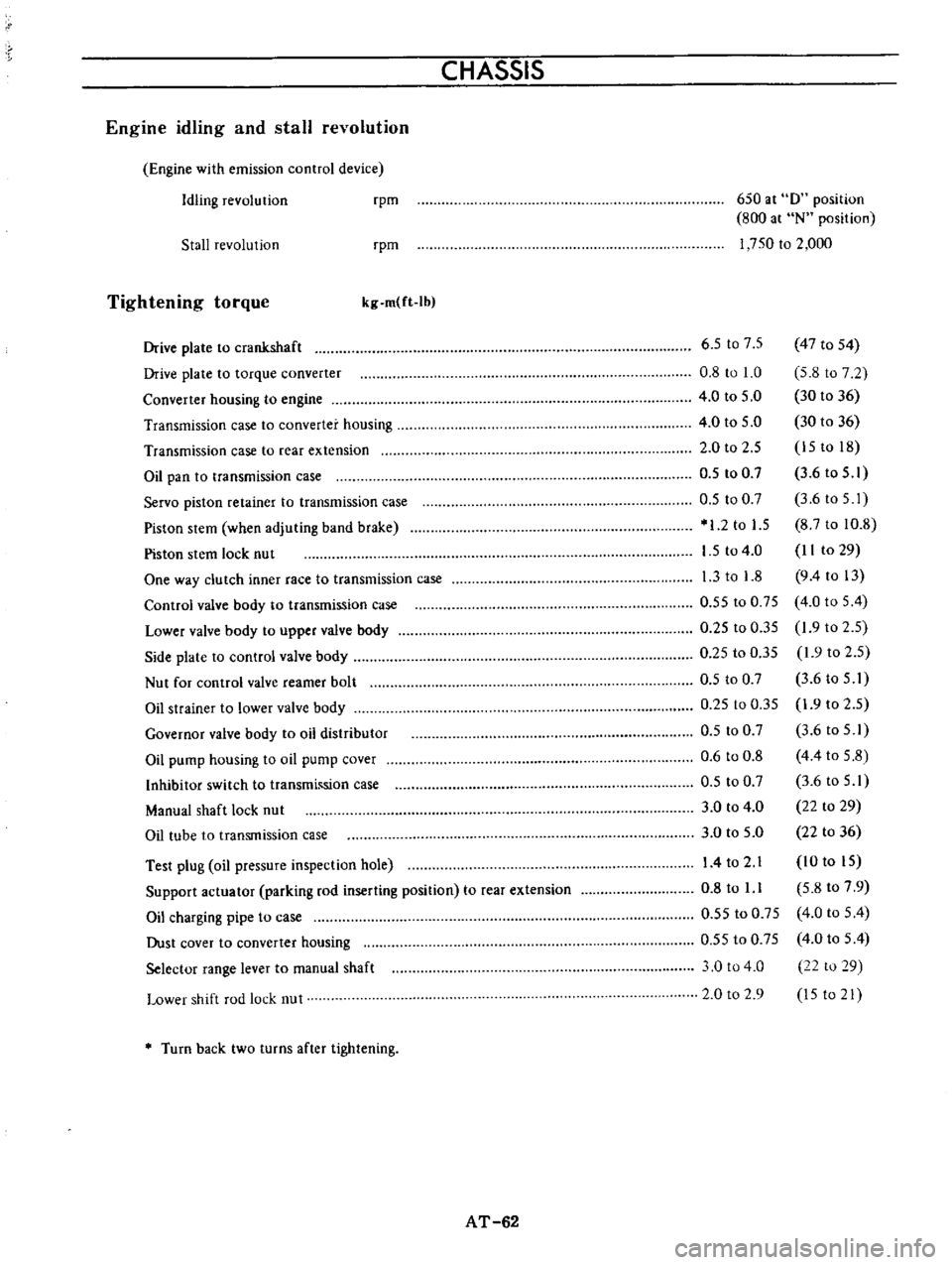
CHASSIS
Engine
idling
and
stall
revolution
Engine
with
emission
control
device
Idling
revolution
rpm
650
at
0
position
800
at
N
position
1
750
to
2
000
Stall
revolution
rpm
Tightening
torque
kg
m
ft
Ib
Test
plug
oil
pressure
inspection
hole
Support
actuator
parking
rod
inserting
position
to
rear
extension
Oil
charging
pipe
to
case
Dust
cover
to
converter
housing
Selector
range
lever
to
manual
shaft
Lower
shift
rod
lock
nut
6
5
t07
5
47
to
54
0
8
to
1
0
5
8
to
7
2
4
0
to
5
0
30
to
36
4
0
to
5
0
30
to
36
2
0
to
2
5
15
to
18
0
5
to
0
7
3
6
to
5
1
0
5
to
0
7
3
6toS
I
1
2
to
1
5
8
7
to
10
8
1
5
to
4
0
II
to
29
1
3
to
1
8
9
4
to
13
0
55
to
0
75
4
0
to
5
4
0
25
to
0
35
1
9
to
2
5
0
25
to
0
35
1
9
to
2
5
0
5
to
0
7
3
6
to
5
I
0
25
to
0
35
1
9
to
2
5
0
5
to
0
7
3
6
to
5
1
0
6
to
0
8
4
4
to
5
8
0
5
to
0
7
3
6
to
5
1
3
0
to
4
0
22
to
29
3
0
to
5
0
22
to
36
14
to
2
1
10
to
15
0
8
to
l
l
5
8
to
7
9
0
55
to
0
75
4
0
to
5
4
0
55
to
0
75
4
0
to
5
4
3
0
to
4
0
22
to
29
2
0
to
2
9
15
to
21
Drive
plate
to
crankshaft
Drive
plate
to
torque
converter
Converter
housing
to
engine
Transmission
case
to
converter
housing
Transmission
case
to
rear
extension
Oil
pan
to
transmission
case
Servo
piston
retainer
to
transmission
case
Piston
stem
when
adjuting
band
brake
Piston
stem
lock
nut
One
way
clutch
inner
race
to
transmission
case
Control
valve
body
to
transmission
case
Lower
valve
body
to
upper
valve
body
Side
plate
to
control
valve
body
Nut
for
control
valve
reamer
bolt
Oil
strainer
to
lower
valve
body
Governor
valve
body
to
oil
distributor
Oil
pump
housing
to
oil
pump
cover
Inhibitor
switch
to
transmh
sion
case
Manual
shaft
lock
nut
Oil
tube
to
transmission
case
Turn
back
two
turns
after
tightening
AT
62
Page 163 of 513

STEERING
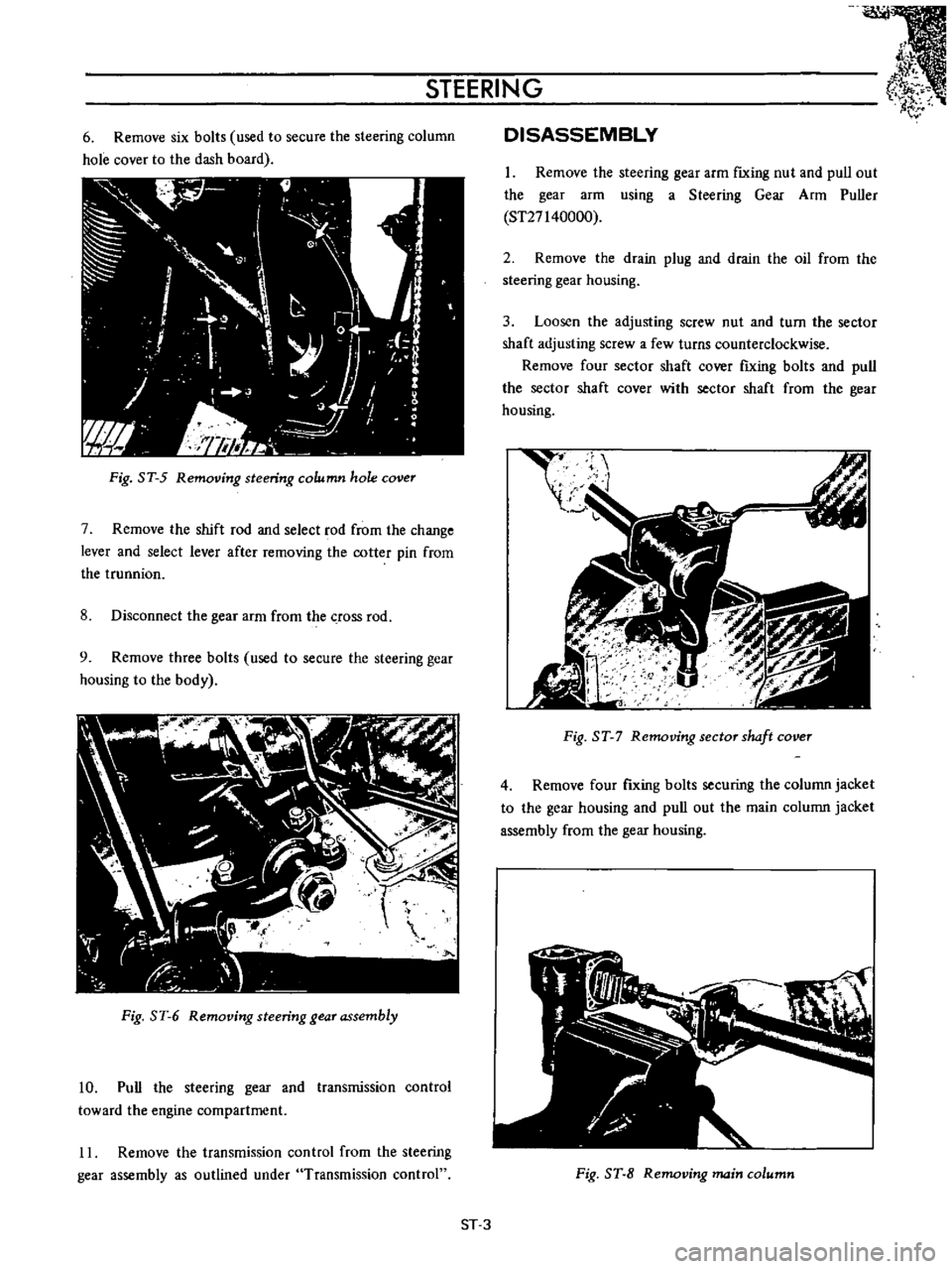
6
Remove
six
bolts
used
to
secure
the
steering
column
hole
cover
to
the
dash
board
Fig
ST
5
Removing
steering
column
hole
cover
7
Remove
the
shift
rod
and
select
rod
from
the
change
lever
and
select
lever
after
removing
the
cotter
pin
from
the
trunnion
8
Disconnect
the
gear
arm
from
the
crOSS
rod
9
Remove
three
bolts
used
to
secure
the
steering
gear
housing
to
the
body
Fig
ST
6
Removing
steering
gear
assembly
10
Pull
the
steering
gear
and
transmission
control
toward
the
engine
compartment
11
Remove
the
transmission
control
from
the
steering
gear
assembly
as
outlined
under
Transmission
control
DISASSEMBLY
1
Remove
the
steering
gear
arm
fIxing
nut
and
pull
out
the
gear
arm
using
a
Steering
Gear
Arm
Puller
ST27140000
2
Remove
the
drain
plug
and
drain
the
oil
from
the
steering
gear
housing
3
Loosen
the
adjusting
screw
nut
and
turn
the
sector
shaft
adjusting
screw
a
few
turns
counterclockwise
Remove
four
sector
shaft
cover
fIxing
bolts
and
pull
the
sector
shaft
cover
with
sector
shaft
from
the
gear
housing
t
I
gJ
I
I
Fig
ST
7
Removing
sector
shaft
cover
4
Remove
four
fIxing
bolts
securing
the
column
jacket
to
the
gear
housing
and
pull
out
the
main
column
jacket
assembly
from
the
gear
housing
Fig
ST
8
Removing
main
column
ST
3
Page 278 of 513
Tool
number
Tool
name
ST23850000
Transmission
rear
oil
seal
remover
ST23520000
Fork
rod
pin
punch
t
I
ST23620000
Fork
rod
guide
ST23820000
Adapter
setting
plate
ST22730000
Bearing
puller
SERVICE
EQUIPMENT
Figure
mm
inch
42
25
to
42
4
15
835
to
15
842
CJ
SE
6
Description
For
removing
the
transmission
rear
oil
seal
For
removal
of
the
fork
rod
retaining
pins
For
supporting
the
interlock
ball
when
installing
the
fork
rod
Setting
plate
of
the
transmission
gear
assembly
For
removing
the
transmission
main
counter
and
drive
shaft
bearings
S
M
reference
page
See
Fig
No
Fig
TM
29
Fig
TM
18
Fig
TM44
Fig
TM
47
Fig
PD
Il
Fig
TM
42
Fig
TM
15
Fig
TM
22
Page 279 of 513
SERVICE
EQUIPMENT
Automatic
transmission
tool
Tool
number
S
M
reference
Tool
name
Figure
Description
page
See
mm
inch
Fig
No
ST25050001
Oil
pressure
gauge
Use
for
checking
hydraulic
Fig
AT
112
set
Y
pressure
SE119
ST07870000
Transmission
case
Use
for
setting
transmission
Page
AT
37
stand
SE120
ST25850000
Sliding
hammers
Use
for
removing
oil
pump
Fig
AT
56
r
SE121
ST25420001
ST2542000
Clutch
spring
compressor
Use
for
assembling
or
disassem
bling
front
and
rear
clutch
Fig
AT
79
Fig
AT
86
SE122
sE
7
Page 301 of 513

GENERAL
INFORMATION
steering
wheel
should
be
secured
to
maintain
a
straight
ahead
position
TIE
DOWN
The
front
tie
down
hook
is
used
the
both
front
end
of
tension
rod
Do
not
apply
the
hook
at
the
center
of
tension
rod
or
suspension
member
The
rear
tie
down
hook
is
used
the
both
front
shackle
of
rear
spring
APPROXIMATE
REFILL
CAPACITY
Liter
U
S
A
measure
I
Imp
measure
Sedan
Fuel
tank
Coupe
with
heater
Cooling
system
without
heater
40
L
38
L
4
9
L
4
2
L
2
7
L
0
54
L
1
2
L
5
5
L
0
75
L
0
24
L
Oil
pan
Oilf1lter
Transmission
case
Manual
Automatic
Differential
case
Steering
gear
box
RECOMMENDED
GASOLINE
FUEL
Use
a
no
lead
or
low
lead
gasoline
with
a
minimum
octane
rating
of
87
the
average
of
the
Research
and
1O
gal
8Y
gal
10
gal
8
gal
5
v
qt
4
M
qt
4
Y
6
qt
3
Y
qt
2Ji
qt
2
qt
1
pt
I
pt
2
pt
2
pt
5Ji
qt
4
qt
1
pt
1
pt
pt
pi
Motor
Octane
Numbers
in
the
U
S
When
the
figure
is
based
on
the
Research
Octane
Number
use
a
gasoline
with
a
minimum
octane
rating
of
91
RON
in
Canada
RECOMMENDED
LUBRICANTS
GI
5
r
Page 302 of 513
GENERAL
INFORMATION
RECOMMENDED
LUBRICANT
SPECI
FICATIONS
Item
Gasoline
engine
oil
o
Transmission
and
steering
Differential
Automatic
TIM
fluid
Multipurpose
grease
Brake
and
clutch
fluid
Antifreeze
coolant
i
Specifications
SAE
Classification
SO
or
SE
API
G
L
4
API
GL
5
Type
DEXRON
NLGI2
DOT
3
Long
Life
Coolant
GI
6
Remarks
Furthermore
refer
to
SAE
recommended
viscosity
table
See
Page
GI
5
Lithium
soap
base
Page 306 of 513

EMISSION
CONTROL
AND
TUNE
UP
EMISSION
CONTROL
SYSTEM
AN
D
ENGINE
TUNE
UP
CONTENTS
BASIC
MECHANICAL
SYSTEM
ET
Checking
and
adjusting
dash
pot
Adjusting
intake
and
exhaust
valve
automatic
transmission
model
only
ET
9
clearances
ET
1
Checking
carburetor
return
spring
ET
9
Checking
and
adjustin9
drive
belt
ET
2
Checking
choke
mechanism
choke
valve
Retightening
cylinder
head
bolts
manifold
and
linkagel
ET
9
nuts
and
carburetor
securing
nuts
ET
2
Checking
anti
dieseling
solenoid
ET
9
Checking
engine
oil
ET
2
Replacing
fuel
filter
ET
10
Replacing
oil
filter
ET
3
Checking
fuel
lines
hoses
pipings
Changing
engine
coolant
L
L
C
ET
3
connections
etc
ET10
Checking
cooling
system
hoses
and
THROTTLE
OPENER
CONTROL
SYSTEM
ET
10
connections
ET
4
Checking
and
adjusting
throttle
opener
ET
13
Checking
vacuum
fittings
hoses
and
TRANSMISSION
CONTROLLED
VACUUM
connections
ET
4
ADVANCE
SYSTEM
ET
17
Checking
engine
compression
ET
4
Checking
electrical
advance
control
system
ET
19
Checking
exhaust
manifold
heat
control
AUTOMATIC
TEMPERATURE
CONTROL
AIR
valve
ET
5
CLEANER
A
T
C
AIR
CLEANER
ET
20
IGNITION
AND
FUEL
SYSTEM
ET
5
Replacing
carburetor
air
cleaner
filter
ET
20
Checking
battery
ET
5
Checking
hot
air
control
valve
ET
20
Checking
and
adjusting
ignition
timing
ET
5
CRANKCASE
EMISSION
CONTROL
Checking
or
replacing
distributor
breaker
SYSTEM
ET
22
point
condenser
and
spark
plugs
ET
6
Checking
or
replacing
PCV
valve
ET
23
Checking
distributor
ignition
wiring
and
Checking
ventilation
hoses
ET
23
ignition
coil
ET
7
EVAPORATIVE
EMISSION
CONTROL
Checking
distributor
cap
and
rotor
ET
7
SYSTEM
ET
23
Adjusting
carburetor
id
Ie
rpm
and
Checking
engine
compartment
hose
mixture
ratio
ET
8
connections
and
fuel
vapor
control
valves
ET
23
Checking
fuel
tank
vacuum
relief
valve
operation
ET
24
BASIC
MECHANICAL
SYSTEM
1
Start
engine
and
run
it
until
it
is
heated
to
operating
temperature
or
at
least
more
than
800C
I760F
of
engine
oil
temperature
then
stop
engine
Adjusting
intake
and
exhaust
valve
clearances
Valve
clearance
adjustment
should
be
made
while
engine
is
stationary
To
adjust
proceed
as
follows
2
Rotate
crankshaft
to
bring
No
1
cylinder
in
top
dead
center
on
its
compression
stroke
3
Remove
valve
rocker
cover
to
gain
access
to
valve
ET
1