1973 DATSUN B110 wheel
[x] Cancel search: wheelPage 96 of 513
CHASSIS
Reinstallation
Reinstall
the
wheel
bearing
in
reverse
sequence
of
removal
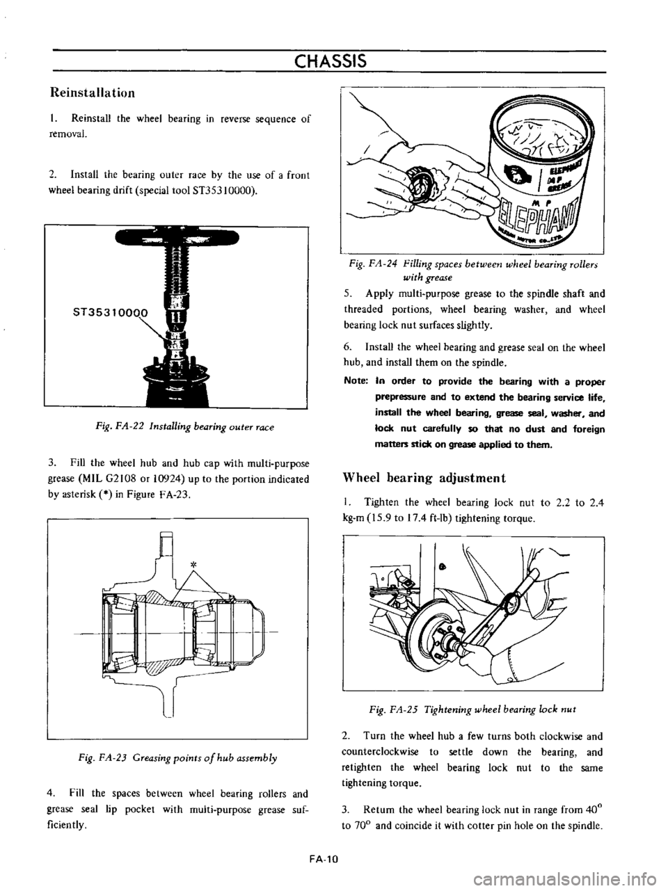
2
Install
the
bearing
outer
race
by
the
use
of
a
froot
wheel
bearing
drift
special
tool
ST353
10000
Fig
FA
22
Installing
bearing
outer
race
3
Fill
the
wheel
hub
and
hub
cap
with
multi
purpose
grease
MIL
G2108
or
10924
up
to
the
portion
indicated
by
asterisk
in
Figure
F
A
23
l
I
L
I
I
P
p
r
Fig
FA
23
Greasing
points
of
hub
assembly
4
Fill
the
spaces
between
wheel
bearing
rollers
and
grease
seal
lip
pocket
with
multi
purpose
grease
suf
ficiently
FA
10
Fig
FA
24
Filling
spaces
betweetJ
wheel
bearing
rollers
with
grease
5
Apply
multi
purpose
grease
to
the
spindle
shaft
and
threaded
portions
wheel
bearing
washer
and
wheel
bearing
lock
nut
surfaces
slightly
6
Install
the
wheei
bearing
and
grease
seal
on
the
wheel
hub
and
install
them
on
the
spindle
Note
In
order
to
provide
the
bearing
with
a
proper
prepressure
and
to
extend
the
bearing
service
life
install
the
wheel
bearing
grease
seal
washer
and
lock
nut
carefully
so
that
no
dust
and
foreign
matters
stick
on
grease
applied
to
them
Wheel
bearing
adjustment
I
Tighten
the
wheel
bearing
lock
nut
to
2
2
to
2
4
kg
m
15
9
to
174
ft
lb
tightening
torque
Fig
FA
25
Tightening
wheel
bearing
lock
nut
2
Turn
the
wheel
hub
a
few
turns
both
clockwise
and
counterclockwise
to
settle
down
the
bearing
and
retighten
the
wheel
bearing
lock
nut
to
the
same
tightening
torque
3
Return
the
wheel
bearing
lock
nut
in
range
from
400
to
700
and
coincide
it
with
cotter
pin
hole
on
the
spindle
Page 97 of 513
FRONT
AXLE
FRONT
SUSPENSION
t
t
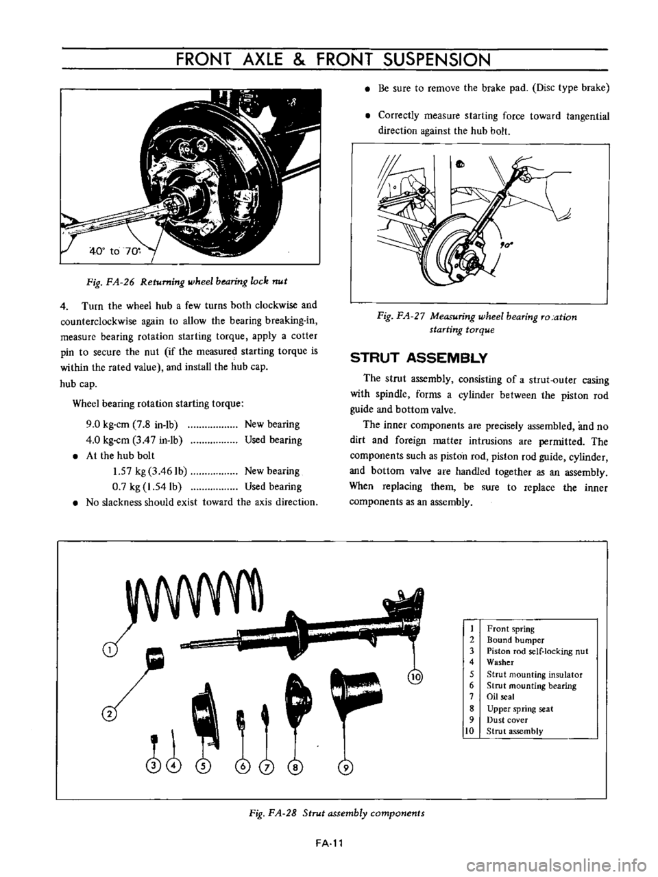
Fig
FA
26
Returning
wheel
bearing
lock
nut
4
Turn
the
wheel
hub
a
few
turns
both
clockwise
and
counterclockwise
again
to
allow
the
bearing
breaking
in
measure
bearing
rotation
starting
torque
apply
a
cotter
pin
to
secure
the
nut
if
the
measured
starting
torque
is
within
the
rated
value
and
install
the
hub
cap
hub
cap
Wheel
bearing
rotation
starting
torque
9
0
kg
cm
7
8
in
1b
4
0
kg
cm
3
4
7
in
1b
At
the
hub
bolt
1
57
kg
3
461b
New
bearing
0
7
kg
1
54lb
Used
bearing
No
slackness
should
exist
toward
the
axis
direction
New
bearing
Used
bearing
J
o
i
@
j
Be
sure
to
remove
the
brake
pad
Disc
type
brake
Correctly
measure
starting
force
toward
tangential
direction
against
the
hub
bolt
Fig
FA
27
Measuring
wheel
bearing
ro
ation
starting
torque
STRUT
ASSEMBLY
The
strut
assembly
consisting
of
a
strut
outer
casing
with
spindle
forms
a
cylinder
between
the
piston
rod
guide
and
bottom
valve
The
inner
components
are
precisely
assembled
and
no
dirt
and
foreign
matter
intrusions
are
permitted
The
components
such
as
piston
rod
piston
rod
guide
cylinder
and
bottom
valve
are
handled
together
as
an
assembly
When
replacing
them
be
sure
to
replace
the
inner
components
as
an
assembly
1
2
3
4
5
6
7
8
9
10
Front
spring
Bound
bumper
Piston
rod
self
locking
nut
Washer
Strut
mounting
insulator
Strut
mounting
bearing
Oil
seal
Upper
spring
seat
Dust
cover
Strut
assembly
Fig
FA
28
Strut
assembly
components
FA
l1
Page 98 of 513
fl
i
i
I
1
I
I
i
2
4
L
thi7
lrr
I
1
1
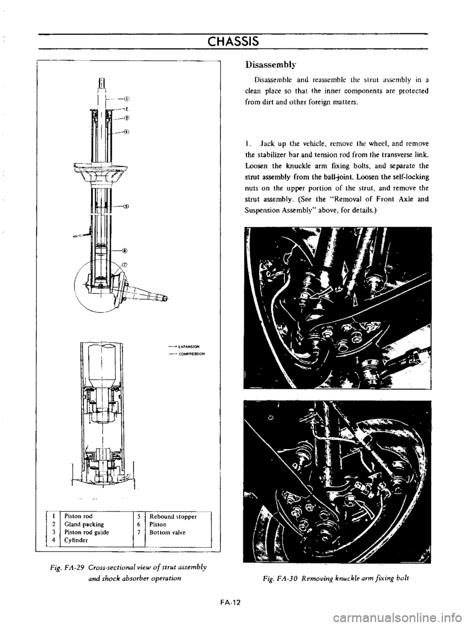
Piston
rod
2
Gland
packing
3
Piston
rod
guide
4
Cylinder
CHASSIS
ESSION
5
Rebound
stopper
6
Piston
7
Bottom
valve
Fig
FA
29
Cross
sectional
view
of
strut
assembly
and
shock
absorber
operation
Disassembly
Disassemble
and
reassemble
the
strut
assembly
in
a
clean
place
so
that
the
inner
components
are
protected
from
dirt
and
other
foreign
matters
Jack
up
the
vehicle
remove
the
wheel
and
remove
the
stabilizer
bar
and
tension
rod
from
the
transverse
link
Loosen
the
knuckle
arm
fIxing
bolts
and
separate
the
strut
assembly
from
the
ball
joint
Loosen
the
self
locking
nuts
on
the
upper
portion
of
the
strut
and
remove
the
strut
assembly
See
the
Removal
of
Front
Axle
and
Suspension
Assembly
above
for
details
Fig
FA
JO
Removitlg
ktluckle
arm
fixitlg
bolt
FA
12
Page 104 of 513
CHASSIS
r
I
El
0
3
to
1
0
mm
0
0118
to
0
0394
in
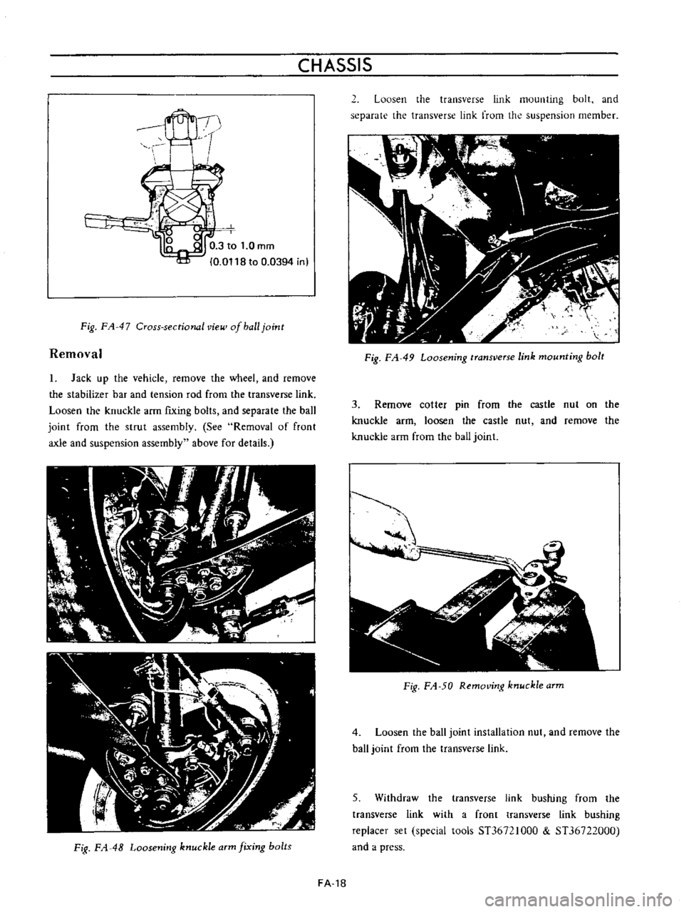
Fig
FA
47
Cross
sectional
vie
of
ball
joint
Removal
1
Jack
up
the
vehicle
remove
the
wheel
and
remove
the
stabilizer
bar
and
tension
rod
from
the
transverse
link
Loosen
the
knuckle
arm
fiXing
bolts
and
separate
the
ball
joint
from
the
strut
assembly
See
Removal
of
front
axle
and
suspension
assembly
above
for
details
Fig
FA
48
Loosening
knuckle
arm
fixing
bolts
2
Loosen
the
transverse
link
mounting
bolt
and
separate
the
transverse
link
from
the
suspension
member
Fig
FA
49
Loosening
transverse
link
mounting
bolt
3
Remove
cotter
pin
from
the
castle
nut
on
the
knuckle
arm
loosen
the
castle
nut
and
remove
the
knuckle
arm
from
the
ball
joint
J
iIP
A
i
Fig
FA
50
Removing
knuckle
arm
4
Loosen
the
ball
joint
installation
nut
and
remove
the
haJJ
joint
from
the
transverse
Jink
5
Withdraw
the
transverse
link
bushing
from
the
transverse
link
with
a
front
transverse
link
bushing
replacer
set
special
tools
ST36721000
ST36722000
and
a
press
FA
18
Page 107 of 513
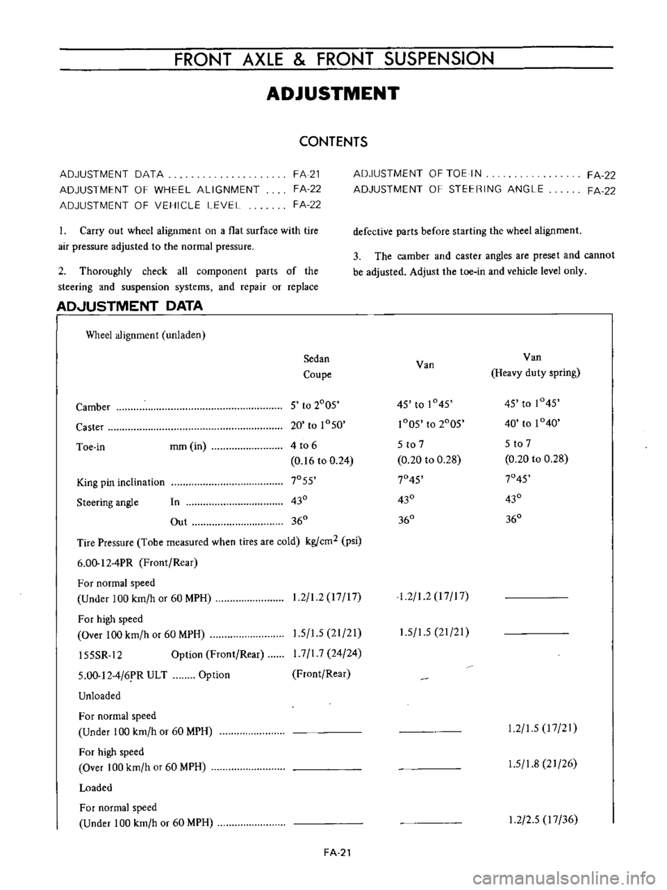
FRONT
AXLE
FRONT
SUSPENSION
ADJUSTMENT
CONTENTS
ADJUSTMENT
DATA
ADJUSTMENT
OF
WHEEL
ALIGNMENT
ADJUSTMENT
OF
VEHICLE
LEVEL
FA
21
FA
22
FA
22
1
Carry
out
wheel
alignment
on
a
flat
surface
with
tire
air
pressure
adjusted
to
the
normal
pressure
2
Thoroughly
check
all
component
parts
of
the
steering
and
suspension
systems
and
repair
or
replace
AD
JUSTMENT
DATA
I
Wheel
alignment
unladen
Sedan
Coupe
Camber
5
to
2005
Caster
20
to
1050
Toe
in
mm
in
4
to
6
0
16
to
0
24
King
pin
inclination
7055
Steering
angle
In
430
Out
360
Tire
Pressure
Tobe
measured
when
tires
are
cold
kgfcm2
psi
6
00
12
4PR
Front
Rear
For
normal
speed
Under
100
km
h
or
60
MPH
For
high
speed
Over
100
km
h
or
60
MPH
15SSR
12
Option
Front
Rear
1
2
1
2
17
17
1
5
1
5
21
21
I
7
I
7
24
24
Front
Rear
5
00
12
4
6
R
ULT
Unloaded
Option
For
normal
speed
Under
100
km
h
or
60
MPH
For
high
speed
Over
100
km
h
or
60
MPH
Loaded
For
normal
speed
Under
100
km
h
or
60
MPH
FA
21
ADJUSTMENT
OF
TOE
IN
ADJUSTMENT
OF
STEERING
ANGLE
FA
22
FA
22
defective
parts
before
starting
the
wheel
alignment
3
The
camber
and
caster
angles
are
preset
and
cannot
be
adjusted
Adjust
the
toe
in
and
vehicle
level
only
Van
Van
Heavy
duty
spring
45
to
1045
45
to
1045
1005
to
2005
40
to
1040
5
to
7
5
to
7
0
20
to
0
28
0
20
to
0
28
7045
7045
430
430
360
360
1
2
1
2
I
7
I
7
1
5
1
5
21
21
1
2
1
5
17
21
1
5
1
8
21
26
1
2
2
5
17
36
Page 108 of 513
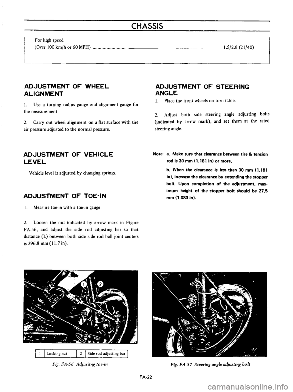
CHASSIS
For
high
speed
Over
100
km
h
or
60
MPH
ADJUSTMENT
OF
WHEEL
ALIGNMENT
Use
a
turning
radius
gauge
and
alignment
gauge
for
the
measurement
2
Carry
out
wheel
alignment
on
a
flat
surface
with
tire
air
pressure
adjusted
to
the
normal
pressure
ADJUSTMENT
OF
VEHICLE
LEVEL
Vehicle
level
is
adjusted
by
changing
springs
ADJUSTMENT
OF
TOE
IN
Measure
toe
in
with
a
toe
in
gauge
2
Loosen
the
nut
indicated
by
arrow
mark
in
Figure
FA
56
and
adjust
the
side
rod
adjusting
bar
so
that
distance
L
between
both
side
side
rod
ball
joint
centers
is
296
8
mm
11
7
in
I
1
I
Locking
nu
t
I
2
I
Side
rod
adjusting
bar
I
Fig
FA
56
Adjusitng
toe
in
1
5
2
8
21
40
ADJUSTMENT
OF
STEERING
ANGLE
1
Place
the
front
wheels
on
turn
table
2
Adjust
both
side
steering
angle
adjusting
bolts
indicated
by
arrow
mark
and
set
them
al
the
rated
steering
angle
Note
8
Make
sure
that
clearance
between
tire
tension
rod
is
30
mm
11
181
in
or
more
b
When
the
clearance
is
less
than
30
mm
1
181
in
inaease
the
clearance
by
extending
the
stopper
bolt
Upon
completion
of
the
adjustment
max
imum
height
of
the
stopper
bolt
should
be
27
5
mm
1
083
in
Fig
FA
57
Steering
angle
adjusting
bolt
FA
22
Page 109 of 513
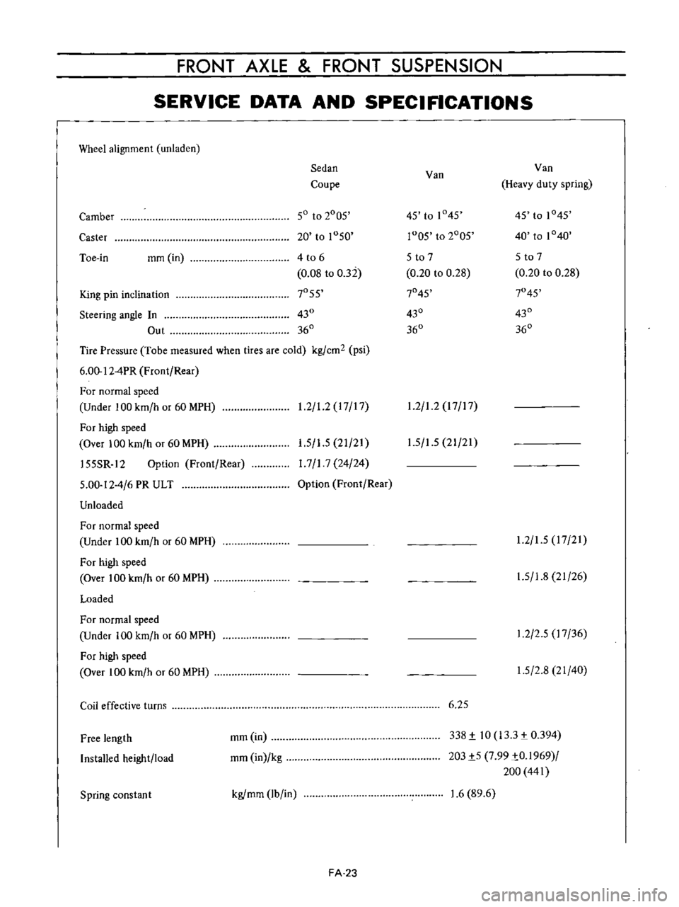
FRONT
AXLE
FRONT
SUSPENSION
SERVICE
DATA
AND
SPECIFICATIONS
Wheel
alignment
unladen
Sedan
Van
Van
Coupe
Heavy
duty
spring
Camber
50
to
2005
45
to
1
45
45
to
1045
Caster
20
to
1050
r005
to
2005
40
to
1040
Toe
in
mm
in
4
t06
5
to
7
5
to
7
0
08
to
032
0
20
to
0
28
0
20
to
0
28
King
pin
inclination
7055
7045
7045
Steering
angle
In
430
430
430
Out
360
360
360
Tire
Pressure
Tobe
measured
when
tires
are
cold
kg
cm2
psi
6
00
12
4PR
Front
Rear
For
normal
speed
Under
100
km
h
or
60
MPH
1
2
1
2
17
17
1
2
1
2
17
17
For
high
speed
Over
100
km
h
or
60
MPH
155SR
12
Option
Front
Rear
5
00
12
4
6
PR
ULT
Unloaded
1
5
1
5
21
21
1
7
1
7
24
24
Option
Front
Rear
1
5
1
5
21
21
For
normal
speed
Under
100
km
h
or
60
MPH
For
high
speed
Over
100
km
h
or
60
MPH
Loaded
1
2
1
5
17
21
1
5
1
8
21
26
For
normal
speed
Under
100
km
h
or
60
MPH
For
high
speed
Over
100
km
h
or
60
MPH
1
2
2
5
17
36
1
5
2
8
21
40
Coil
effective
turns
6
25
Free
length
Installed
height
load
mm
in
mm
in
kg
338
i
10
133
0394
203i5
7
99
iO
1969
200
441
Spring
constan
t
kgfmm
lb
in
1
6
89
6
FA
23
Page 110 of 513

CHASSIS
Strut
assembly
Strut
outer
diameter
Piston
rod
diameter
mmlin
nml
in
45
17
7
18
0
709
15
0
984
Piston
diameter
mmlin
Damping
force
at
piston
speed
0
3
m
sec
Expansion
kg
Ib
Compression
kg
lb
48
106
22
48
5
Piston
rod
Bend
limit
Wear
limit
mm
in
0
1
0
0039
mm
in
0
025
0
0010
Piston
cylinder
Bend
limit
Wear
limit
inside
mm
in
mm
in
0
2
0
0079
0
1
0
0039
17
0
669
Stabilizer
bar
diameter
mm
in
Front
wheel
bearing
rotation
starting
torque
kg
cm
in
lb
Ball
joint
shaking
torque
kg
cm
in
lb
Ball
joint
end
play
axial
direction
mm
in
9
0
7
8
35
to
60
30
4
to
52
1
0
3
to
1
0
0
0118
to
0
0394
TIGHTENING
TORQUE
Front
axle
Brake
disc
rotor
and
hub
assembly
tightening
torque
Wheel
bearing
lock
nut
Disc
brake
caliper
fixing
bolt
Buffle
plate
installation
screw
Brake
disc
assembly
installation
bolt
kg
m
ft
lb
4
4
to
5
9
31
8
to
42
7
2
2
to
2
4
15
9
to
174
4
6
to
6
1
33
3
to
44
1
0
3
to
0
4
2
1
to
2
9
2
7
to
3
7
19
5
to
26
8
Strut
assembly
Gland
packing
tightening
torque
Piston
rod
self
locking
nut
Upper
support
nut
8
0
to
11
0
57
8
to
79
5
3
6
to
4
5
26
0
to
32
5
1
6
to
2
1
I
1
6
to
15
2
Transverse
link
and
ball
joint
Bolts
used
to
install
the
knuckle
arm
to
strut
Ball
joint
castle
nut
Bolts
used
to
install
the
transverse
link
to
ball
4
6
to
6
1
33
3
to
44
1
5
5
to
7
4
39
8
to
53
5
FA
24