1973 DATSUN B110 wheel
[x] Cancel search: wheelPage 122 of 513
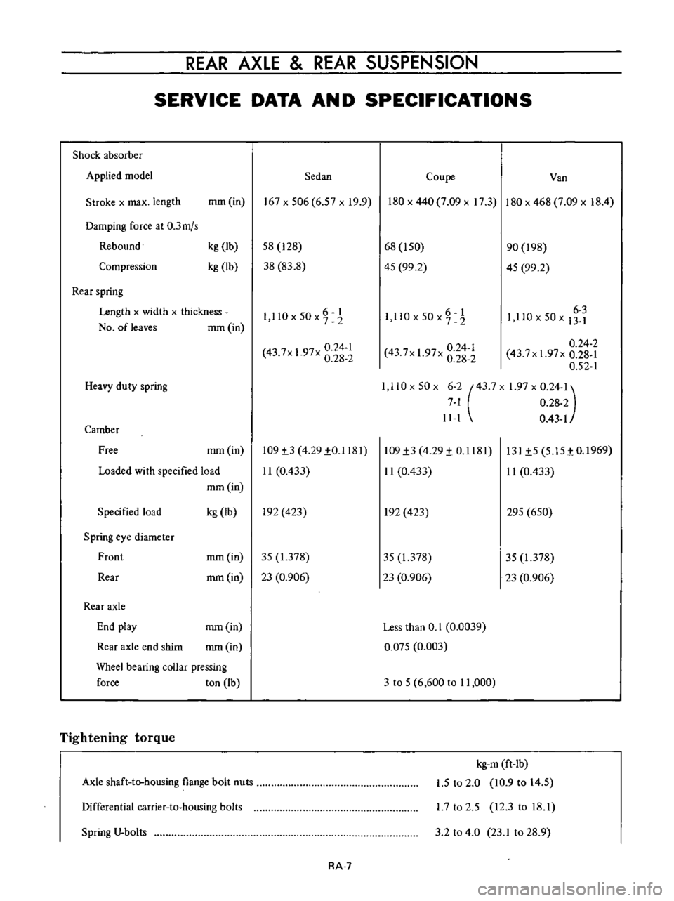
REAR
AXLE
REAR
SUSPENSION
SERVICE
DATA
AN
D
SPECIFICATIONS
Shock
absorber
Applied
model
Sedan
Coupe
Van
Stroke
x
max
length
mm
in
167x506
6
57xI9
9
180
x
440
7
09
x
17
3
180
x
468
7
09
x
18
4
Damping
force
at
0
3mjs
Rebound
Compression
kg
Ib
kg
lb
58
128
38
83
8
68
I
50
45
99
2
90
198
45
99
2
Rear
spring
Length
x
widlh
x
thickness
NO
ofleaves
mm
in
6
I
1
llOx50x72
O
6
1
I
ll
x50x7
2
6
3
1
110
x
50
x
13
1
0
24
1
43
7x
1
97x
0
28
2
0
24
2
43
7xI
97x
0
28
1
0
52
1
1
110x50x
6
2
43
7X
1
97
x
0
24
1
7
1
0
28
2
11
1
0
43
1
0
24
1
43
7x
1
97x
0
28
2
Heavy
duty
spring
Camber
Free
mm
in
109
t3
4
29
1
0
1181
11
0
433
109
1
3
4
29
1
0
1181
11
0
433
131
1
5
5
15
tO
1969
11
0
433
Loaded
wi
th
specified
load
mm
in
Specified
load
kg
Ib
In
423
In
423
295
650
Spring
eye
diameter
Front
mm
in
35
1
378
35
1
378
35
1
378
Rear
mm
in
23
0
906
23
0
906
23
0
906
Rear
axle
End
play
mm
in
Less
than
0
1
0
0039
Rear
axle
end
shim
mm
in
0
Q75
0
003
Wheel
bearing
coUar
pressing
force
ton
Ib
3
to
5
6
600
to
11
000
Tightening
torque
Axle
shaft
to
housing
flange
bolt
nuts
kg
m
ft
lb
1
5
to
2
0
10
9
to
14
5
L7
to
2
5
12
3
to
18
1
Differential
carrier
to
housing
bolts
Spring
V
bolts
3
2
to
4
0
23
1
to
28
9
RA
7
Page 123 of 513
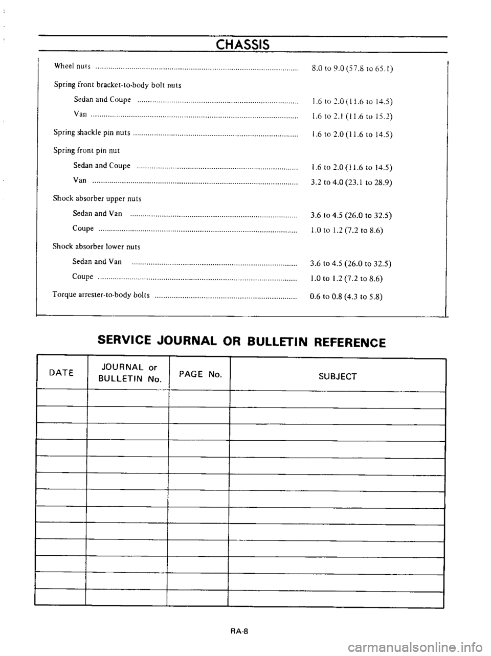
CHASSIS
Wheel
nuts
8
0
to
9
0
7
8
to
65
1
Spring
front
bracket
to
body
bolt
nuts
Sedan
and
Coupe
Van
6
to
0
1
6
to
14
5
6
to
I
11
6
to
15
2
Spring
shackle
pin
nuts
1
6
to
0
11
6
to
14
5
Spring
front
pin
nut
Sedan
and
Coupe
Van
6
to
2
0
1
6
to
14
5
3
2
to
4
0
23
1
to
28
9
Shock
absorber
upper
nuts
Sedan
and
Van
Coupe
3
6
to
4
5
26
0
to
32
5
0
to
1
7
2
to
8
6
Shock
absorber
lower
nuts
Sedan
and
Van
Coupe
3
6
to
4
5
26
0
to
32
5
0
to
I
2
7
2
to
8
6
0
6
to
0
8
4
3
to
5
8
Torque
arrester
to
body
bolts
SERVICE
JOURNAL
OR
BULLETIN
REFERENCE
DATE
JOURNAL
or
BULLETIN
No
PAGE
No
SUBJECT
RA
8
Page 126 of 513
CHASSIS
DESCRIPTION
The
Datsun
1200
series
new
models
adopt
a
hydraulic
brake
Dis
brake
or
two
leading
shoe
type
drum
brake
is
used
for
the
front
wheels
and
leading
trailing
shoe
type
drum
brake
is
used
for
the
rear
wheels
With
adoption
of
the
disc
brake
safety
at
high
speed
range
driving
is
further
improved
For
the
master
cylinder
either
single
type
or
tandem
type
is
used
There
are
two
types
of
tandem
type
master
cylinder
one
is
for
disc
brake
and
the
other
for
drum
brake
Under
the
standard
specifications
h0wever
the
tandem
type
master
cylinder
is
used
for
disc
brake
and
single
type
is
used
for
drum
brake
The
tandem
master
cylinder
provides
a
dual
brake
system
improving
safety
The
hand
brake
is
of
a
mechanical
type
which
brakes
the
rear
wheels
through
the
control
lever
and
steel
wire
The
control
lever
is
located
between
the
driver
and
assistant
seats
and
can
be
operated
easily
BRAKE
PEDAL
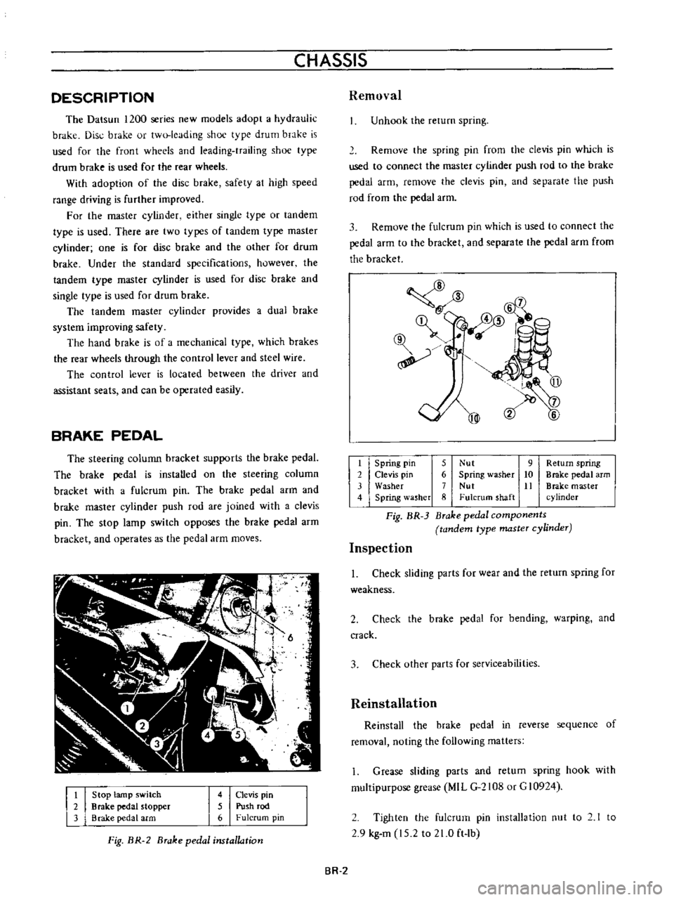
The
steering
colunm
bracket
supports
the
brake
pedaL
The
brake
pedal
is
instaUed
on
the
steering
column
bracket
with
a
fulcrum
pin
The
brake
pedal
arm
and
brake
master
cylinder
push
rod
are
joined
with
a
clevis
pin
The
stop
lamp
switch
opposes
the
brake
pedal
arm
bracket
and
operates
as
the
pedal
arm
moves
t
2
3
Stop
lamp
switch
Brake
pedal
stopper
Brake
pedal
arm
4
Clevis
pin
5
Push
rod
6
Fulcrum
pin
Fig
BR
2
Brake
pedal
installation
Removal
Unhook
the
rerum
spring
Remove
the
spring
pin
from
the
clevis
pin
which
is
used
to
connect
the
master
cylinder
push
rod
to
the
brake
pedal
arm
remove
the
clevis
pin
and
separate
the
push
rod
from
the
pedal
arm
3
Remove
the
fulcrum
pin
which
is
used
to
connect
the
pedal
arm
to
the
bracket
and
separate
the
pedal
arm
from
the
bracket
@
mm
l6
qf
@
@
t
Spring
pin
5
Nut
9
Return
spring
2
Clevis
pin
6
Spring
washer
10
Brake
pedal
arm
3
Washer
7
Nut
It
Brake
master
4
Spring
lasher
8
Fulcrum
shaft
cylinder
Fig
BR
3
Brake
pedal
components
tandem
type
master
cylinder
Inspection
1
Check
sliding
parts
for
wear
and
the
return
spring
for
weakness
2
Check
the
brake
pedal
for
bending
warping
and
crack
3
Check
other
parts
for
serviceabilities
Reinstallation
Reinstall
the
brake
pedal
in
reverse
sequence
of
removal
noting
the
following
matters
1
Grease
sliding
parts
and
retum
spring
hook
with
multipurpose
grease
MIL
G
2108
or
G
10924
2
Tighten
the
fulcrum
pin
installation
nut
to
2
1
to
2
9
kg
m
15
2
to
21
0
ft
lb
BR
2
Page 132 of 513
CHASSIS
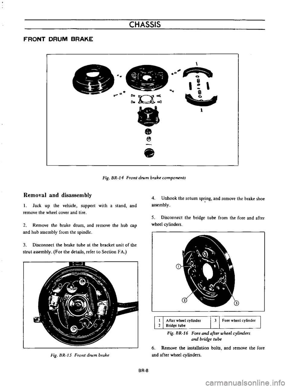
FRONT
DRUM
BRAKE
14
I
l
Fig
BR
14
Front
drum
brake
components
Removal
and
disassembly
Jack
up
the
vehicle
support
with
a
stand
and
remove
the
wheel
cover
and
tire
2
Remove
the
brake
drum
and
remove
the
hub
cap
and
hub
assembly
from
the
spindle
3
Disconnect
the
brake
tube
at
the
bracket
unit
of
the
strut
assembly
For
the
details
refer
to
Section
FA
R
W
i
1
t
V
t
1
1
d
j
2
rl
s
J
J
i
Z
j
Fig
BR
15
Front
drum
brake
4
Unhook
the
return
spring
and
remove
the
brake
shoe
assembly
5
Disconnect
the
bridge
tube
from
lhe
fore
and
after
wheel
cylinders
I
I
After
wheel
cylinder
Bridge
tube
I
3
I
Fore
wheel
cylinder
Fig
BR
16
Fore
and
after
wheel
cylinders
and
bridge
tube
6
Remove
the
installation
bolts
and
remove
the
fore
and
after
wheel
cylinders
BR
B
Page 133 of 513
7
Remove
the
brake
disc
installation
bolt
and
remove
the
brake
disc
from
the
spindle
8
Disassemble
the
wheel
cylinders
Inspection
l
Drums
If
they
show
score
excessive
out
of
round
and
so
forth
reconditioning
by
machining
is
required
Brake
drum
inner
diameter
203
2
mm
8
00
in
Drum
inside
out
of
roundness
Below
0
02
mm
0
0008
in
Max
allowable
drum
inner
diameter
204
5
mm
8
051
in
2
Linings
If
brake
shoe
linings
are
incomp1etedly
seated
soiled
or
greasy
or
deteriorated
due
to
excessive
heating
repair
or
replace
them
If
the
thickness
of
the
lining
is
less
than
1
5
mm
0
0591
in
replace
it
Note
a
If
oil
or
grease
is
found
on
linings
clean
thoroughly
with
carbon
tetrachloride
or
gasoline
b
After
installing
and
bonding
lining
grind
the
lining
face
to
a
diameter
equal
to
the
brake
drum
3
Check
the
adjusting
cams
for
their
smooth
operation
4
Return
springs
If
they
are
considerably
weak
replace
them
Return
spring
dimension
Wire
diameter
x
free
length
turns
3
2
x
118
mm
20
5
0
1260
x
4
65
in
20
5
Load
x
length
55
kg
I21
lb
x
127
1
mm
5
00
in
13
4
0
528
ilL
rnv
0
t
6
hl
03
118
4
65
FREE
LENGTH
UNIT
mm
in
Fig
BR
J
7
Return
spring
BRAKE
5
Check
the
brake
disc
for
distortion
6
Check
the
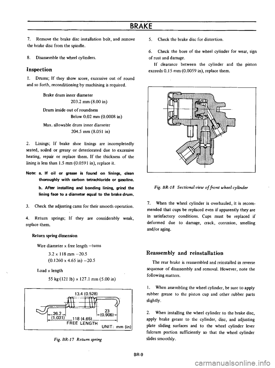
bore
of
the
wheel
cylinder
for
wear
sign
of
rust
and
damage
If
clearance
between
the
cylinder
and
the
piston
exceeds
0
15
mm
0
0059
in
replace
them
Fig
BR
J
8
Sectional
view
of
front
wheel
cylinder
7
When
the
wheel
cylinder
is
overhauled
it
is
recom
mended
that
cups
be
replaced
even
if
apparently
they
are
in
satisfactory
conditions
Cups
must
be
replaced
if
deformed
due
to
damage
crack
corrosion
smelling
andf
or
aging
Reassembly
and
reinstallation
The
rear
brake
is
reassembled
and
reinstalled
in
reverse
sequence
of
disassembly
and
removal
However
note
the
following
matters
When
assembling
the
wheel
cylinder
be
sure
to
apply
rubber
grease
to
the
piston
cup
and
other
rubber
parts
slightly
2
When
installing
the
wheel
cylinder
to
the
brake
disc
apply
brake
grease
to
the
cylinder
disc
and
adjusting
plate
sliding
surfaces
and
to
the
wheel
cylinder
lever
fulcrum
portion
sufficiently
so
that
the
wheel
cylinder
slides
smoothly
BR
9
Page 135 of 513

BRAKE
CYLINDER
SIDE
PISTON
SIDE
COMPR
ESSION
DECOMPRESSION
Movement
exceeding
the
elastic
displacement
is
released
with
slipping
on
the
seal
surface
Returns
in
elastic
displacement
of
the
seal
Fig
BR
21
Piston
seal
automatic
adjusting
operation
Brake
pad
Replacement
1
Jack
up
front
unit
of
the
vehicle
and
remove
lhe
front
wheeL
2
Remove
clip
from
the
retaining
pin
and
supporting
the
brake
pad
remove
the
retaining
pin
and
coil
spring
I
I
Brake
pad
2
Retaining
pin
I
31
Clip
Fig
BR
22
Removing
retaining
pin
3
Unhook
the
hanger
spring
and
withdraw
the
brake
pad
and
shim
with
a
pair
of
pliers
BR
ll
Fig
HR
2
Withdrawing
brake
pad
and
shim
Note
When
the
brake
pad
is
removed
do
not
depress
the
brake
pedal
or
otherwise
the
piston
will
come
out
Inspection
Clearance
between
the
brake
pad
and
rotor
is
adjusted
automatically
Check
the
brake
pad
for
wear
after
the
first
10
000
km
6
000
miles
driving
and
every
5
000
km
3
000
miles
thereafter
1
Clean
the
brake
pad
with
carbon
tetrachloride
or
gasoline
2
When
oil
and
or
grease
is
heavily
sticked
on
the
pad
or
when
deteriorated
or
deformed
due
to
overheating
replace
the
pad
with
a
new
one
3
When
thickness
of
the
friction
material
pad
is
less
than
1
6
mm
0
0630
in
replace
Replace
when
total
pad
thickness
is
less
than
6
1
mm
0
2402
in
Note
Replace
pads
as
a
set
Replacement
at
only
one
position
may
cause
uneven
brake
effect
It
is
recommended
that
rotation
of
pads
be
made
periodically
4
Check
the
rotor
Refer
to
Rotor
inspection
Reinstallation
1
Clean
the
calipers
and
piston
pad
installing
parts
Note
Do
not
use
mineral
oil
Be
careful
not
to
apply
oil
on
the
rotor
2
Depress
the
piston
into
the
cylinder
so
that
new
pad
can
be
installed
Page 136 of 513

CHASSIS
Fig
BR
24
Depression
piston
A
and
B
into
cylinder
Nota
a
Nota
that
brake
fluid
may
overflow
from
the
reservoir
It
is
recommeooed
that
operation
be
carried
out
by
loosening
the
breather
to
release
brake
fluid
b
The
piston
can
be
easily
pushed
in
by
hand
But
if
pushed
excessively
the
groove
of
piston
goes
inside
of
seal
as
shown
in
Figure
BR
25
and
the
seal
will
be
damaged
When
the
piston
is
pushed
excessively
into
the
cylinder
remove
the
brake
assembly
disassemble
it
push
out
the
piston
to
the
arrow
direction
as
shown
in
Figure
BR
25
and
reassemble
r
w
i
@
I
I
I
I
i
I
I
I
1
I
1
1
Piston
ieat
1
2
I
Normal
position
I
Fig
BR
25
Piston
pushing
in
position
3
Install
pad
and
anti
squeal
shim
assemble
the
anti
squeal
spring
and
retaining
pin
and
secure
them
with
clip
ARROW
MARK
Fig
BR
26
Arrow
mark
on
shim
I
Install
the
shim
so
that
the
arrow
mark
points
the
rotor
forward
rotating
direction
2
Apply
the
coil
spring
to
the
retaining
pin
which
is
distanced
from
the
air
bleeder
4
When
the
pad
is
installed
depress
the
brake
pedal
several
times
so
as
to
settle
down
the
pad
in
the
position
Caliper
assembly
Removal
L
Remove
the
brake
pad
Refer
to
Pad
re
placement
2
Disconnect
the
brake
tube
from
the
wheel
cylinder
3
Remove
the
strut
assembly
and
knuckie
arm
instal
lation
bolt
so
as
to
ease
removal
of
the
caliper
assembly
installation
bolt
BR
12
Page 137 of 513
BRAKE
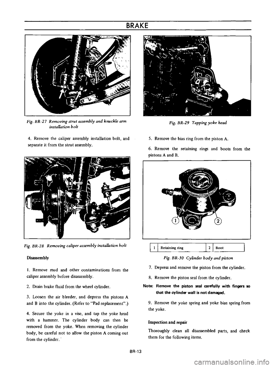
Fig
BR
27
Removing
strut
assembly
and
knuckle
arm
installation
bolt
4
Remove
the
caliper
assembly
installation
bolt
and
separate
it
from
the
strut
assembly
Fig
BR
28
Removing
caliper
assembly
instaUation
bolt
Disassembly
I
Remove
mud
and
other
contaminations
from
the
caliper
assembly
before
disassembly
2
Drain
brake
fluid
from
the
wheel
cylinder
3
Loosen
the
air
bleeder
and
depress
tha
pistons
A
and
B
into
the
cylinder
Refer
to
Pad
replacement
4
Secure
the
yoke
in
a
vise
and
tap
the
yoke
head
with
a
hammer
The
cylinder
body
can
then
be
removed
from
the
yoke
When
removing
the
cylinder
body
be
careful
not
to
allow
the
piston
A
coming
out
from
the
cylinder
BR
13
i
c
J
l
l
7
I
0
I
I
i
I
f
1
1
J
t
1
Fig
BR
29
Tapping
yoke
head
5
Remove
the
bias
ring
from
the
piston
A
6
Remove
the
retaining
rings
and
boots
from
the
pistons
A
and
B
J
l
lj
7
fI
II
l
j
B
11
I
Retaining
ring
121
Boot
Fig
BR
30
Cylinder
body
and
piston
7
Depress
and
remove
the
piston
from
the
cylinder
8
Remove
the
pislon
seal
from
the
cylinder
Note
Remove
the
piston
seal
carefully
with
fingers
so
that
the
cylinder
wall
is
not
damaged
9
Remove
the
yoke
spring
and
yoke
bias
spring
from
the
yoke
Inspection
and
repair
Thoroughly
clean
all
disassembled
parIs
and
check
them
for
the
following
items