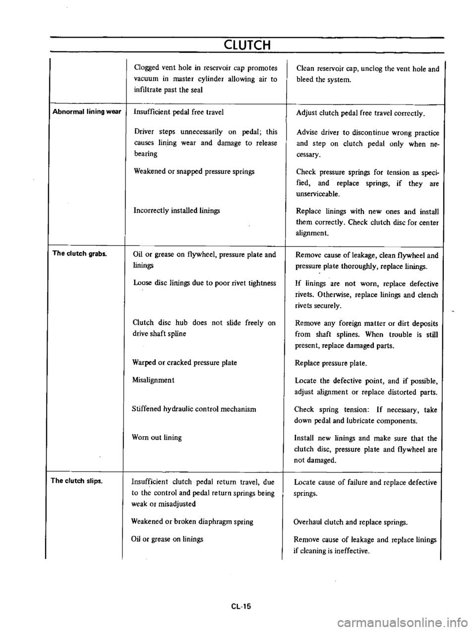
CLUTCH
Clogged
vent
hole
in
reservoir
cap
promotes
vacuum
in
master
cylinder
allowing
air
to
inf1ltrate
past
the
seal
Abnormal
lining
wear
Insufficient
pedal
free
travel
The
clutch
grabs
The
clutch
slips
Driver
steps
unnecessarily
on
pedal
this
causes
lin
jog
wear
and
damage
to
release
bearing
Weakened
or
snapped
pressure
springs
Incorrectly
installed
linings
Oil
or
grease
on
flywheel
pressure
plate
and
linings
Loose
disc
linings
due
to
poor
rivet
tightness
Clutch
disc
hub
does
not
slide
freely
on
drive
shaft
spline
Warped
or
cracked
pressure
plate
Misalignment
Stiffened
hydraulic
control
mechanism
Wom
out
lining
Insufficient
clutch
pedal
return
travel
due
to
the
control
and
pedal
return
springs
being
weak
or
misadjusted
Weakened
or
broken
diaphragm
spring
Oil
or
grease
on
linings
eLl5
Clean
reservoir
cap
unclog
the
vent
hole
and
bleed
the
system
Adjust
clutch
pedal
free
travel
correctly
Advise
driver
to
discontinue
wrong
practice
and
step
on
clutch
pedal
only
when
ne
cessary
Check
pressure
springs
for
tension
as
speci
fied
and
replace
springs
if
they
are
unserviceable
Replace
linings
with
new
ones
and
install
them
correctly
Check
clutch
disc
for
center
alignment
Remove
cause
of
leakage
clean
flywheel
and
pressure
plate
thoroughly
replace
linings
If
linings
are
not
worn
replace
defective
rivets
Otherwise
replace
linings
and
clench
rivets
securely
Remove
any
foreign
matter
or
dirt
deposits
from
shaft
splines
When
trouble
is
still
present
replace
damaged
parts
Replace
pressure
plate
Locate
the
defective
point
and
if
possible
adjust
alignment
or
replace
distorted
parts
Check
spring
tension
If
necessary
take
down
pedal
and
lubricate
components
Install
new
linings
and
make
sure
tha
t
the
clutch
disc
pressure
plate
and
flywheel
are
not
damaged
Locate
cause
of
failure
and
replace
defective
springs
Overhaul
clutch
and
replace
springs
Remove
cause
of
leakage
and
replace
linings
if
cleaning
is
ineffective
TRANSMISSION
COLUMN
SHIFT
CONTROL
SYSTEM
Removal
Remove
the
steering
wheel
assembly
Fig
TM
54
Rem01
ing
steering
wheel
2
Remove
the
steering
column
shell
cover
turn
signal
and
lighting
switch
completely
Fig
TM
55
Removing
steering
column
shell
cover
Fig
TM
56
Removing
turn
signal
and
lighting
switch
3
Remove
the
snap
ring
and
control
lever
pivot
pin
and
withdraw
the
hand
lever
A
A
V
l
Y
e
f
I
1
I
V
e
tl
f
r
4
2i
L
1
I
Snap
ring
2
Control
lever
pivot
pin
I
3
I
C
washer
Fig
TM
57
Withdrawing
hand
ever
4
Remove
the
C
washer
TM
17
i
MI
ig
r
M
5J
emOVing
change
lever
J
y
Ji
1
r
oJ