Page 57 of 136

Fuel
SJstem
Check
float
needle
and
seat
for
wear
Replace
the
assembly
If
worn
Check
the
throttle
and
choke
bores
In
throttle
body
and
cover
castIng
for
wear
or
out
of
round
Inspect
Idle
adjustIng
needles
for
burrs
or
ndges
Replace
as
reqUIred
Inspect
gaskets
to
ensure
that
they
do
not
ap
pear
hard
or
bnttle
and
that
the
edges
are
not
turned
or
dIstorted
If
any
such
condItIOn
IS
detected
they
must
be
replaced
Check
filter
secreen
screen
for
cloggIng
Clean
and
If
It
IS
dIstorted
or
remaInS
plugged
replace
Check
cluster
for
loose
or
worn
parts
If
damage
or
Ioosene
s
eXists
replace
cluster
assembly
Check
the
hnkage
for
operatIng
condItion
Inspect
the
operatIOn
of
acceleratIng
pump
Pour
gasohne
Into
the
float
chamber
and
operate
the
throttle
hver
Check
conditIOn
of
gasohne
InjectIOn
from
the
acceleratIng
nozzle
Assembly
and
Installation
Assemble
and
Install
the
carburetor
In
I
everse
sequence
of
dIsassembly
and
removal
Replace
the
gaskets
If
necessary
When
dlsassembhng
and
reassembhng
the
In
terlock
hnk
and
related
components
be
careful
not
to
bend
or
deform
the
components
Reassembly
carefully
and
correctly
so
that
all
Interlock
hnks
operate
smoothly
Jets
The
carburetor
performance
depends
on
Jets
and
aIr
bleed
and
the
vehicle
emISSIOns
largely
depends
on
the
carburetor
performan
ce
That
IS
why
these
components
are
manufactured
WIth
utmost
care
To
clean
them
use
gasohne
and
blow
aIr
on
them
ChangIng
Jet
or
air
bleed
sIze
may
cause
III
vehICle
emIssIon
So
they
should
not
be
changed
theIr
numbers
Trouble
Shootmg
In
the
follOWIng
table
the
symptom
and
causes
of
carburetor
troubles
and
remedIes
for
them
are
hsted
to
faclhtate
qUIck
repaIrs
There
are
vanous
causes
of
engIne
trouble
It
sometImes
happens
that
the
completely
effec
tlve
carburetor
seems
apparently
to
have
some
troubles
when
electnc
systern
IS
defec
tIve
Therefore
whenever
the
engIne
has
troubles
electnc
system
must
be
checked
first
before
adjusting
the
carburetor
TROUBLE
SHOOTING
Troubles
POSSible
causes
Remedlc
Overflow
Dirt
accumulated
on
needle
valve
Clean
needle
valve
Fuel
pump
pressure
100
hIgh
RCpJlf
pump
Needle
valve
seat
Improper
Lap
or
replai
e
ExceSSIve
fuel
Fuel
overflows
See
above
I
l
onsumptlon
Each
mam
aIr
bleed
clogged
Clean
80
Page 58 of 136

ruel
Sptem
Troubles
Power
shortage
Improper
IdlIng
Rough
engIne
Idle
or
eogme
stop
Engme
Idle
too
fast
Possible
causes
Gauge
plate
adjustment
mcorrect
Choke
valve
does
not
open
Outlet
valve
seat
of
accelerator
pump
1m
proper
Lmked
openmg
of
secondary
throttle
valve
too
early
each
mam
Jet
clogged
EaLh
throttle
valve
does
not
fully
open
Fuel
pump
operated
Improperly
uel
stramer
clogged
Vacuum
Jet
clogged
Power
vdlve
operated
Improperly
Slow
Jel
dugged
Fat
h
thronle
valve
does
not
close
Secondary
throttle
valve
operated
Im
properly
Eal
h
throttle
valve
shaft
wear
Packing
between
mamfold
and
carburetor
defective
Fuel
overflows
Incorrect
carburetor
adjustment
Idle
speed
Idle
miXture
choke
settmg
Incorrect
baSIC
1
OIt100
tunmg
Incorrect
automatic
temperature
control
air
cleaner
Defect
or
malfunction
of
Igmtlon
system
spark
plug
lugh
tenSion
cable
breaker
JX
Int
Ignition
COIl
etc
Trouble
In
throttle
lInk
and
cable
Incorred
throttle
opener
adjustment
Trouble
In
PCV
valve
Trouble
In
automatic
choke
Defect
or
malfunctIOn
of
Igmhon
s
stem
spark
plug
hIgh
tenSion
cable
breaker
pomt
Ignition
Call
elc
Remedies
Correct
adjustment
Adjust
Lap
or
replace
Adlust
Clean
Adjust
Repair
Clean
Clean
Adlust
Clean
Adlusl
Overhaul
and
dedn
Replace
ReplaLe
tlghtenlllg
See
the
fust
Item
Adjust
Idle
speed
mixture
dnd
tUllIng
Adjust
19mtlon
timing
Adjust
automatlL
temperature
control
air
cleaner
Adjust
or
replaLe
IgllltIun
system
Chel
k
throttle
hnk
and
Lable
Adjust
throttle
opener
Replace
PCV
vJlve
Adjust
auotmJtIL
l
hoke
Adjust
or
replac
e
IgllltIun
system
J
81
Page 59 of 136
Fuel
I
em
Troubles
Engine
hesitatIOn
Car
knock
when
coastIng
EnglOe
does
not
start
82
POSSIble
causes
Eal
h
mam
Jet
slow
Jet
clogged
By
pdss
hole
die
pdssage
dogged
Emulsion
lube
dogged
Idhng
adlostment
mcorrect
Secondary
throttle
valve
operated
1m
properly
Incorrect
throttle
opener
adjustment
Trouble
m
PCV
valve
Defect
or
malfunction
of
Igmtlon
system
spark
plog
ugh
tenSIon
cable
breaker
pomt
IgmtIon
cod
etc
Fuel
overflows
No
fuel
IdlIng
adjustment
mearrect
Fast
Idle
adjustment
mcareeet
Damaged
antl
dlesehng
solenoId
BI
metal
rod
m
contact
WIth
bl
metal
case
RemedIes
Clean
Cledn
lube
lean
Correct
adjustment
Overhaul
and
clean
AdjUstlhroltle
opener
Replace
PCV
valve
Adjust
or
replace
IgJuhan
system
See
the
first
Item
Check
pump
fuel
pIpe
and
needle
valve
Correct
adjustment
Correct
adjustment
Replace
Adlust
Page 60 of 136
Cooling
Sptem
Fig
106
Coolmg
system
C0026
FIg
107
Water
pump
and
front
cover
FIg
1I1S
Water
pump
removal
DESCRIPTION
radiator
w1th
hIgh
coohng
efficiency
and
of
a
pellet
type
thermostat
The
coohng
system
IS
of
a
closed
pressure
type
With
hIgh
coolmg
capablhty
Coohng
water
WATER
PUMP
flowmg
through
resIstance
free
water
passages
m
the
cyhnder
head
and
cyhnder
The
water
pump
IS
a
centrifugal
type
water
block
IS
mamtamed
at
adequate
temperature
pum
WIth
an
alumlpum
d1e
cast
pump
body
range
at
allo
tlmes
by
means
of
an
ample
T
he
olute
chamber
IS
bUIlt
mto
the
front
capacIty
water
pump
of
a
corrugated
fin
type
cover
assembly
and
a
high
pressure
seahng
84
Page 61 of 136

GooliDI
Sptem
mechamsm
IS
adopted
to
prevent
the
water
leakage
and
nOIse
completely
Note
The
water
pump
must
not
be
disassembled
since
the
bearings
are
shrmkage
fitted
to
their
bores
If
any
part
of
water
pump
is
found
defective
replace
pump
assembly
Removal
Dram
coolmg
water
completely
Take
the
fan
belt
ofT
the
pulley
Remove
fan
and
pulley
Remove
the
water
pump
Installation
InstallatIOn
IS
the
reverse
of
removal
THERMOSTAT
A
pellet
type
thermostat
IS
used
m
the
water
outlet
passage
to
control
the
flow
of
coolant
provldmg
fast
engme
warm
up
and
regulatmg
coolant
temperature
A
wax
pellet
m
the
ther
mo
tat
expands
when
heated
and
contracts
when
cooled
The
pellet
IS
connected
through
a
piston
to
a
valve
and
when
the
pellet
IS
heated
pressure
IS
exerted
agamst
a
rubber
dIaphragm
and
the
valve
opens
As
the
pellet
IS
cooled
the
contractIOn
allows
the
sprmg
to
close
the
valve
Removal
Dram
coohng
water
Remove
radiator
hose
Remove
water
outlet
elbow
Then
take
out
the
thermostat
Inspection
To
test
the
thermostat
for
proper
operatmg
temperature
submerg
he
umt
m
a
contamer
of
water
Heat
the
water
and
observe
the
tem
perature
Measure
temperature
when
the
thermostat
valve
Just
starts
rlsmg
If
thermostat
does
not
operate
at
the
above
specIfied
temperatures
It
must
be
replaced
Installation
When
mstalhng
the
thermostat
apply
adheSIve
Three
Bond
to
both
SIdes
of
the
packmg
for
preventIOn
of
water
leakage
In
stall
the
thermostat
m
reverse
sequence
of
removal
USA
Canadd
Olher
coun
t
nes
Valve
opemng
temperature
177
to
r8710
16710
F
183
193
173
Valve
lIft
O
oF
031
203
031
212
031
194
WI
fL
g
0
I
l
1
L
JI
I
I
I
I
a
J
i
o
wa
r
outlet
EI
Thermostat
Fig
109
Thermostat
removal
FIQ
110
Thermostat
inspection
81
Page 62 of 136
Gooliol
SJstem
RADIATOR
The
radiator
IS
of
a
down
flow
type
w1th
an
ex
panslOn
tank
located
on
the
top
of
tube
sec
tlOn
Pressure
IS
applted
to
the
system
and
the
I
eltef
valve
Incorporated
In
the
radiator
filler
cap
controls
the
pressure
at
approximately
13
Ib
sq
In
Removal
DraIn
cooltng
water
DIsconnect
radiator
upper
hose
lower
hose
and
hose
to
the
reservOir
tank
Detach
the
radiator
assembly
by
removmg
SIX
fiXIng
bolts
Inspection
Check
for
water
leakage
and
cracks
USIng
a
cap
tester
If
such
defects
are
detected
repair
88
Fig
111
Radiator
removal
or
replace
the
radIator
assembly
Installation
InstallatIOn
IS
the
reverse
of
removal
Page 63 of 136
Brakes
Jl
r7
I
J
I
lip
b
Ih
ih
p
lIJ
11
yhndu
blolk
2
Spnn
7
Air
hlu
k
r
12
PI
lon
3
LVI
pm
H
Rl
t
llmll
nn
13
lh
L
prm
hlm
8001
I
YOkl
pnn
5
lIJ
n
ll
prill
111
1
lon
Ii
15
Yoh
Fig
112
Front
diSC
brake
components
Movement
exceeding
the
elastic
dISplacement
IS
released
with
slipping
on
the
seal
surf
a
Returns
elastIC
displacement
of
the
seal
CYLINDER
SIDE
DECOMPRESSION
Fig
113
PIston
seal
automatic
adjusting
operation
FRONT
DISC
BRAKE
I
Brake
pad
2
Retalnl
pin
I
Clip
FIg
114
RemOVing
retaining
pm
Rigidity
of
the
cahper
IS
high
brake
pedal
feehng
IS
adequate
and
the
pad
draggIng
IS
piston
operating
stroke
Increases
shpplng
oc
mlmmlzed
The
padqs
returned
by
elastIcity
curs
on
the
plston
seal
surface
and
thus
of
the
piston
seal
When
the
pad
IS
worn
the
clearance
IS
adjusted
automatIcally
88
Page 64 of 136

r
Brakes
Moreover
In
order
to
prevent
brake
squeahng
a
shIm
IS
Inserted
behind
the
pad
BRAKE
PAD
Replacement
Jack
up
front
UnIt
of
the
vehicle
and
remove
the
front
wheel
Remove
clip
from
the
retaining
pin
and
sup
porting
the
brake
pad
remove
the
retaining
pin
and
COil
spring
Unhook
the
hanger
spring
and
Withdraw
the
brake
pad
and
shim
With
a
pair
of
phers
Note
When
the
brake
pad
IS
removed
do
not
depress
the
brake
pedal
or
otherWise
the
piston
will
come
out
Inspection
Clearance
between
the
brake
pad
and
rotor
IS
adjusted
automatically
Check
the
brake
pad
Fig
115
WIthdraWing
brake
pad
and
shIm
for
wear
after
the
first
6
000
miles
driVing
and
every
3
000
miles
thereafter
Clean
the
brake
pad
With
carbon
tetrachloride
or
gasohne
When
011
and
or
grease
IS
heavIly
stlcked
on
the
pad
or
when
deteriorated
or
deformed
due
to
overheating
replace
the
pad
With
a
new
one
When
thickness
of
the
friction
material
pad
IS
less
than
0
0630
In
replace
Replace
when
total
pad
thIckness
IS
less
than
0
2402
In
Note
Replace
pads
as
a
set
Replacement
at
only
one
position
may
cause
uneven
brake
effect
It
IS
recommended
that
rotation
of
pads
be
made
periodically
Check
the
rotor
Reinstallation
Clean
the
calipers
and
piston
pad
installing
parts
Note
Do
not
use
mineral
oil
Be
careful
not
to
apply
oil
on
the
rotor
Depress
the
pIston
Into
the
cyhnder
so
that
new
pad
can
be
Installed
Note
a
Note
that
brake
fluid
may
over
flow
from
the
reservoir
It
is
recommen
ded
that
operation
be
carried
out
by
loosening
the
breather
to
release
brake
fluid
b
The
piston
can
be
easily
pushed
in
by
hand
But
if
pushed
excessively
the
Fig
116
DepreSSion
piston
A
and
B
Into
cylinder
88
 1
1 2
2 3
3 4
4 5
5 6
6 7
7 8
8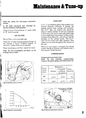 9
9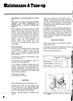 10
10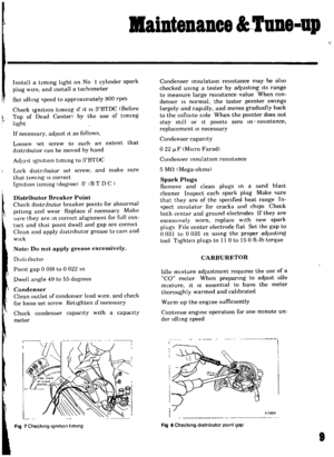 11
11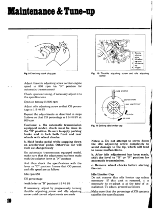 12
12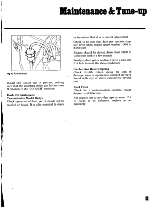 13
13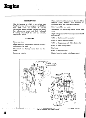 14
14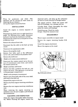 15
15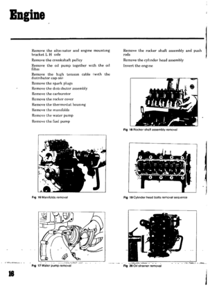 16
16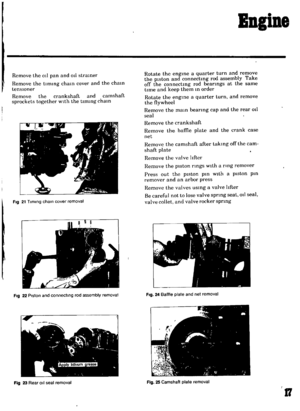 17
17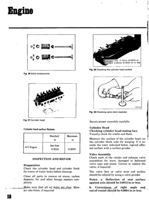 18
18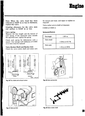 19
19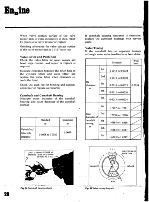 20
20 21
21 22
22 23
23 24
24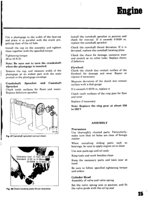 25
25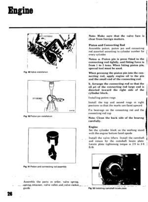 26
26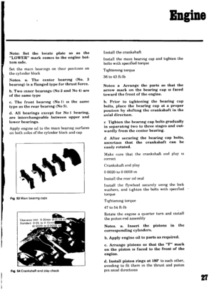 27
27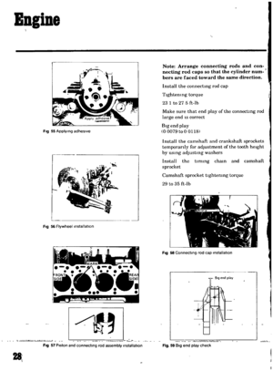 28
28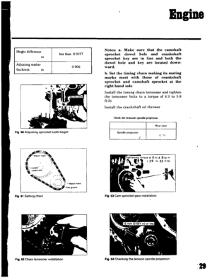 29
29 30
30 31
31 32
32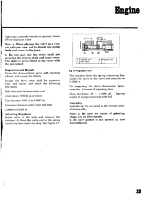 33
33 34
34 35
35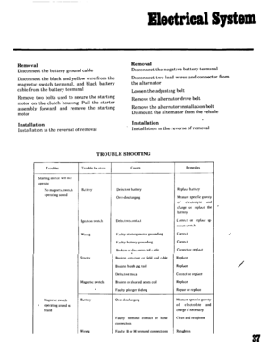 36
36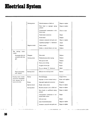 37
37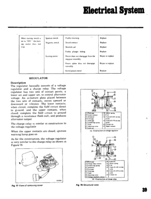 38
38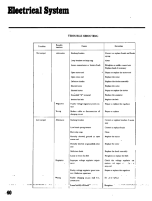 39
39 40
40 41
41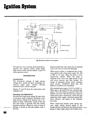 42
42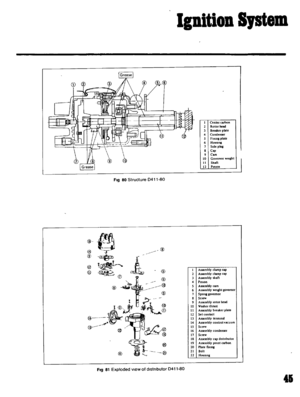 43
43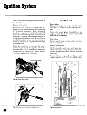 44
44 45
45 46
46 47
47 48
48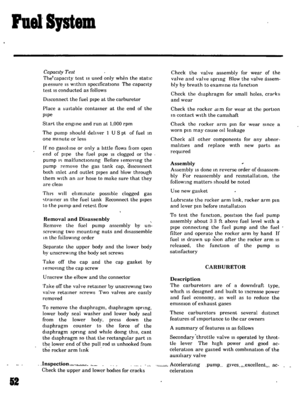 49
49 50
50 51
51 52
52 53
53 54
54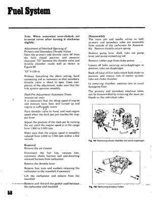 55
55 56
56 57
57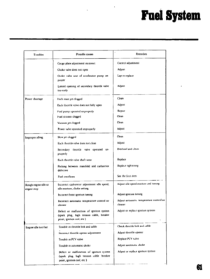 58
58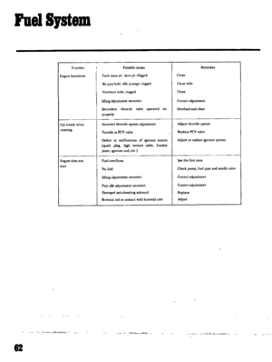 59
59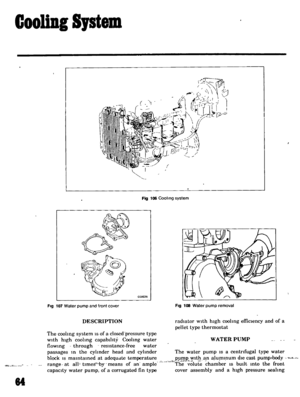 60
60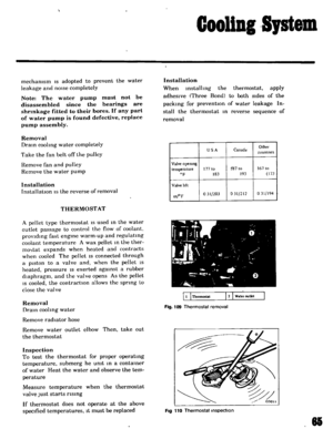 61
61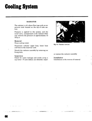 62
62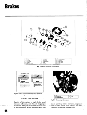 63
63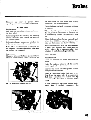 64
64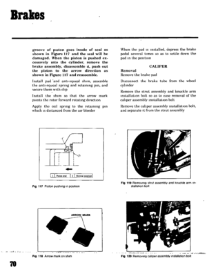 65
65 66
66 67
67 68
68 69
69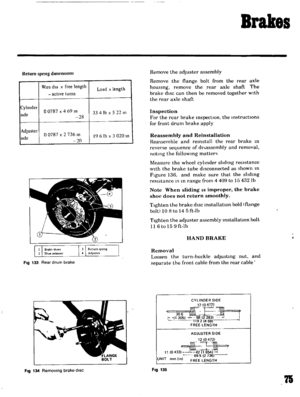 70
70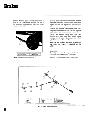 71
71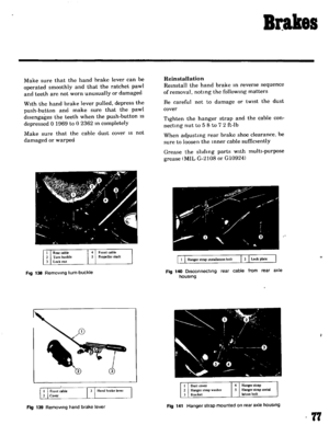 72
72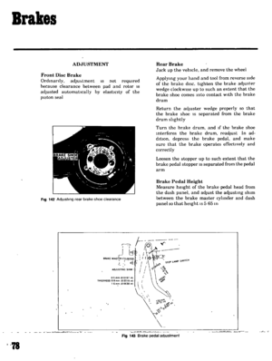 73
73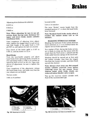 74
74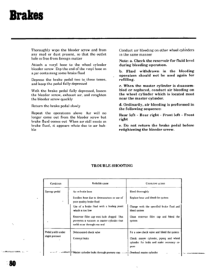 75
75 76
76 77
77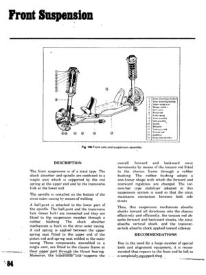 78
78 79
79 80
80 81
81 82
82 83
83 84
84 85
85 86
86 87
87 88
88 89
89 90
90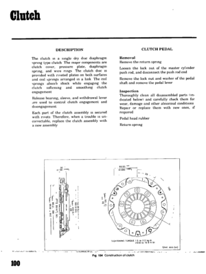 91
91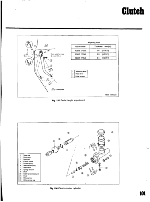 92
92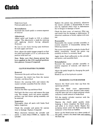 93
93 94
94 95
95 96
96 97
97 98
98 99
99 100
100 101
101 102
102 103
103 104
104 105
105 106
106 107
107 108
108 109
109 110
110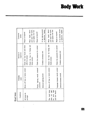 111
111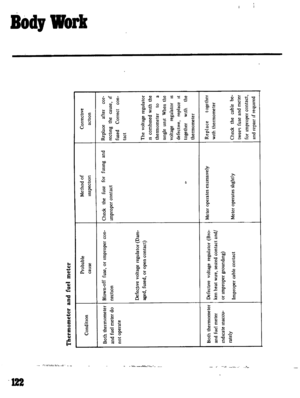 112
112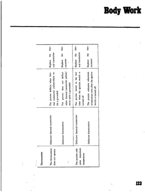 113
113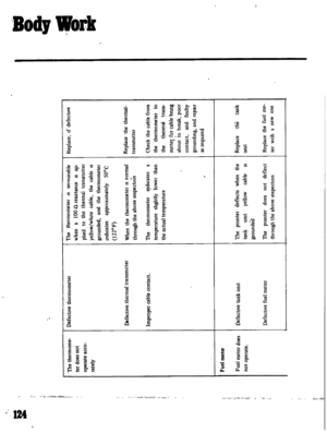 114
114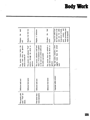 115
115 116
116 117
117 118
118 119
119 120
120 121
121 122
122 123
123 124
124 125
125 126
126 127
127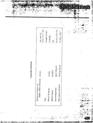 128
128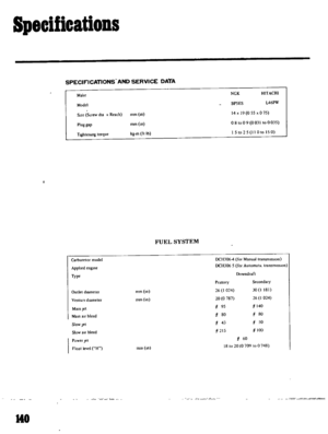 129
129 130
130 131
131 132
132 133
133 134
134 135
135


