Page 25 of 136

Ingine
1
Cut
a
plastIgage
to
the
wIdth
of
the
bearing
and
place
It
m
parallel
with
the
crank
pm
gettmg
clear
of
the
011
hole
Install
the
cap
on
the
assembly
and
tighten
them
together
with
the
specified
torque
Tlghtentng
torque
36
to
43
ft
lb
Note
Be
sure
not
to
turn
the
crankshaft
when
the
plastIgage
is
Inserted
Remove
the
cap
and
measure
wIdth
of
the
plastlgage
at
Its
widest
part
wIth
the
scale
printed
tn
the
plastIgage
envelope
Crankshaft
Sprocket
and
Camshaft
Sprocket
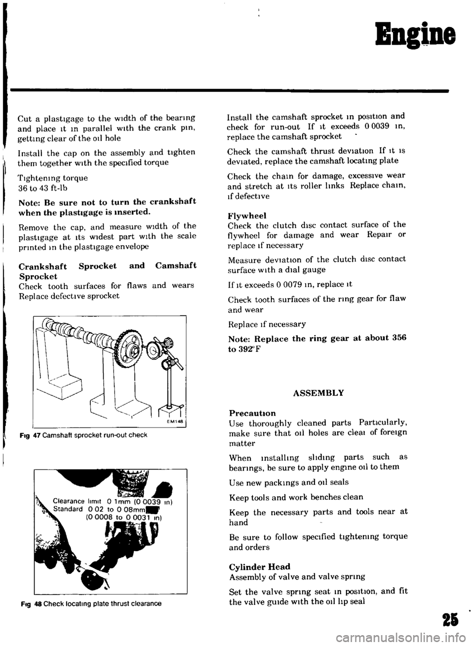
Check
tooth
surfaces
for
flaws
and
wears
Replace
defective
sprocket
EM148
Fig
47
Camshaft
sprocket
run
out
check
Clearance
limit
0
1
mm
00039
m
1
Standard
0
02
to
0
08mm
0
0008
to
0
0031
m
t
Fig
48
Check
locatmg
plate
thrust
clearance
Install
the
camshaft
sprocket
m
posItion
and
check
for
run
out
If
It
exceeds
00039
tn
replace
the
camshaft
sprocket
Check
the
camshaft
thrust
deViatIOn
If
It
IS
deViated
replace
the
camshaft
locatmg
plate
Check
the
cham
for
damage
excessive
wear
and
stretch
at
ItS
roller
Imks
Replace
cham
If
defective
Flywheel
Check
the
clutch
diSC
contact
surface
of
the
flywheel
for
damage
and
wear
Repair
or
replace
If
necessary
Measure
deVtat10n
of
the
clutch
dISC
contact
surface
with
a
dial
gauge
If
It
exceeds
0
0079
m
replace
1t
Check
tooth
surfaces
of
the
ring
gear
for
flaw
and
wear
Replace
If
necessary
Note
Replace
the
ring
gear
at
about
356
to
392
F
ASSEMBLY
PrecautIOn
Use
thoroughly
cleaned
parts
PartIcularly
make
sure
that
011
holes
are
cleal
of
foreign
matter
When
mstalltng
sltdmg
parts
such
as
bearings
be
sure
to
apply
engme
011
to
them
Use
new
packmgs
and
011
seals
Keep
tools
and
work
benches
clean
Keep
the
necessary
parts
and
tools
near
at
hand
Be
sure
to
follow
specified
tIghtemng
torque
and
orders
Cylinder
Head
Assembly
of
valve
and
valve
sprmg
Set
the
valve
sprmg
seat
m
poSItIon
and
fit
the
valve
gUIde
with
the
011
hp
seal
21
Page 125 of 136

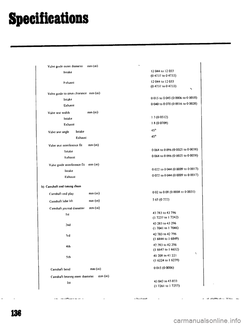
Specifications
V
dve
gUIde
ouler
diameter
mm
tn
Intake
12044
to
12033
04737
1004733
I
Xh
JU51
12044
to
12033
04737
to
0
4733
Valve
gUide
to
stem
dearance
mm
m
Inldke
0015
to
0045
0
0006
to
00018
Exh
lUSf
0040
to
0
070
0
0016
to
0
0028
Valve
seat
width
mm
m
Jntake
I
3
0
0512
Exhaust
I
8
0
0709
Valve
seat
angle
Intake
450
Exhaust
450
Valve
sed
t
mterference
fit
mm
m
IntJ
ke
o
064
to
0096
0
0025
to
0
0038
I
xhaust
0064
to
0
096
0
0025
to
0
0038
V
live
gUide
mterference
fit
mm
m
Intake
0022
100044
0
0009
to
0
0017
Exhaust
0022
to
0
044
0
0009
to
0
0017
b
Cam
haft
and
lImmg
cham
Camshaft
end
play
mm
m
o
02
to
0
08
0
0008
to
00031
Camshaft
lobe
11ft
mm
m
565
0
222
Camshaft
Journal
diameter
mm
m
1st
43
783
1043796
I
7237
to
I
7242
2nd
43
283
to
43
296
I
7041
to
1
7
46
lrd
42
783
10
42
796
I
6844
to
I
6849
4th
42
783
to
42
296
I
6647
to
1
6652
5th
41
208
to
41
221
I
6224
to
I
6229
Camshaft
bend
mm
m
0015
0
006
Camshaft
bearmg
lOner
d13meter
mm
m
1st
43843
to
43
833
I
7261
to
1
7257
p
138
Page 128 of 136
1
It
t
ir
4
I
1
1
J
i
t
1
f
Ii
fj
A
l
1
t
i
I
J
1my
t
It
ff
r
car
k
t
f
11
v
1
t
t
COOLING
SYSTEM
0
JJ
DimenSIOns
of
radIator
core
Height
x
Width
x
Thickness
mm
m
330
x
344
x
32
13
0
x
135
x
I
26
Type
Corrugate
fm
type
Radiator
fm
spacmg
mm
m
2
5
0
098
RadIator
capacity
K
cat
hoC
335
Cap
workIng
pressure
kg
cm2
Ib
sq
In
09
t
0
I
13
t
14
Water
capacity
with
heater
e
US
qt
Imp
qt
49
S
v
6
471
i
t
fj
looIo
t
lk
i
J
l