Page 6 of 136
fable
of
Contents
BODY
WORK
SPECIFICATIONS
I
HOOD
112
SERVICE
DATA
130
Removal
112
ENGINE
134
InstallatIOn
112
General
SpeCificatIOn
134
HOOD
LOCK
112
Tlghtemng
Torque
134
Removal
112
SpeCIficatIOn
135
Adjustment
112
Coohng
System
139
LubncatlOn
114
Fuel
System
140
TRUNK
LID
LOCK
116
Starter
142
Removal
116
Alternator
143
Adjustment
116
Regulator
144
TRUNK
LID
TORSION
BAR
116
Dlstnbutor
145
DOOR
CONSTRUCTION
117
IgnItIOn
Cot
145
WIRING
DIAGRAMS
118
CLUTCH
146
BULB
SPECIFICATIONS
120
NOTES
174
HEADLAMP
121
THERMOMETER
AND
FUEL
METER
122
OIL
PRESSURE
AND
IGNITION
WARNING
LAMPS
126
I
I
t
I
3
Page 38 of 136

llectrical
Spt
When
Harting
lWltch
I
IgllltlUn
iwltch
FJuhy
rctuflung
Repldce
set
10
OFf
the
slJrl
motor
do
nut
MJgnclK
Wltdl
Seiad
contJr
l
Repldcc
IIlg
I
op
Shorted
1
011
Replace
Faulty
plunger
slidmg
Replace
StJflillg
motOr
Pillion
does
not
dlsengJge
from
the
Repair
or
replace
nng
gedr
smoothly
Pinion
sphne
dot
110t
disengage
Repan
or
replJce
moothly
SCl7Cd
pinIOn
metal
Replace
REGULATOR
Description
The
regulator
basically
consists
of
a
voltage
regulator
and
a
charge
relay
The
voltage
regulator
has
two
sets
of
contact
poInts
a
lower
set
and
upper
set
to
control
alternator
voltage
An
at
mature
plate
placed
between
the
two
sets
of
contacts
moves
upward
or
downward
or
Vibrates
The
lower
contacts
when
clo
ed
complete
the
field
CIrCUIt
dIrect
to
glOund
and
the
upper
contacts
when
closed
complete
the
field
CIrCUIt
to
ground
through
a
resIstam
e
field
COl
and
produces
alternator
output
The
charge
lelay
IS
SimIlar
In
constructIOn
to
the
voltage
regulator
When
the
upper
contacts
are
closed
IgnitIOn
warnIng
lamp
goes
on
As
for
the
constructIOn
the
voltage
regulator
IS
very
SImIlar
to
the
charge
relay
as
shown
In
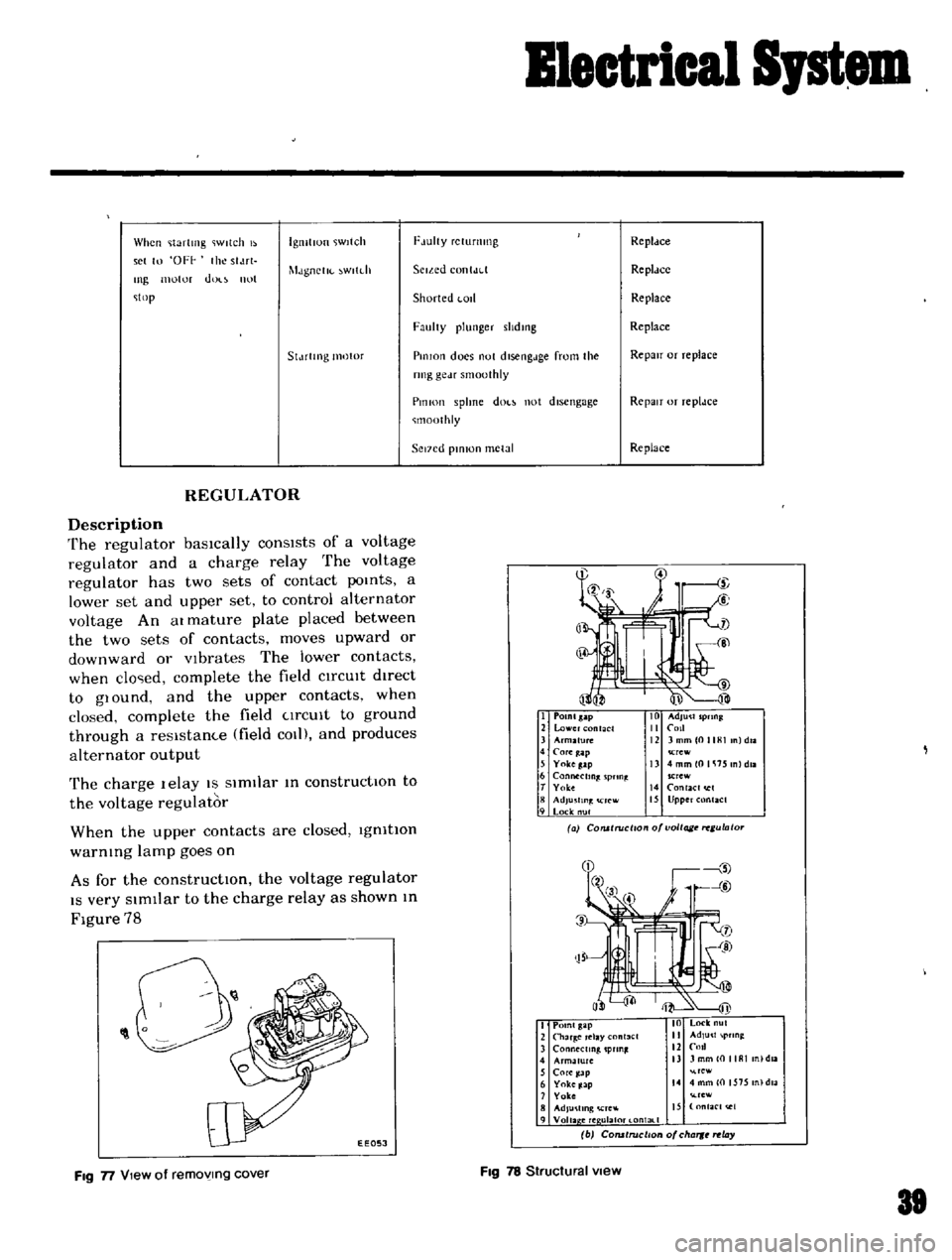
Figure
78
I
POlnlsap
2
lower
nt
CI
3
Arm2fu1C
4
COfe
ap
5
Yokeg
lp
6
Connecting
pnn
t
T
Yolce
8
AdJu
fln
rcw
9
Lock
nul
Crew
13
4mmlOlli15
nldll
SCrew
14
RlaCI
I
15
Upper
Rlact
a
COlUlruci
o
o
voltage
ulato
O
0
1
EEOSJ
I
Point
gap
2
Char
Clay
nl3el
3
ConMctmg
pun
4
Armature
nl
daa
5
Core
ap
re
6
Yoke
Jap
14
4
mm
0
1575
n
dla
7
Yoke
rew
8
AdJu
llng
Cre
IS
nfaC
t
e1
9
Voila
ere
ulal0t
l
ontal
1
b
COfUtruclton
of
cha
rt
ay
FIg
n
View
of
removing
cover
FIg
78
Structural
view
81
Page 110 of 136
Bod
Work
BULB
SPECIFICATIONS
Speclflca
tlons
SAE
Trade
Number
Headlight
umt
2V
50
40W
60
2
Duectlonal
and
parking
light
2V
23
8W
1034
SIde
marker
light
2V
8W
67
LIcense
plate
light
2V
7
5W
89
Rear
combination
light
TaIllight
2V
23
8W
1034
Stop
brake
light
2V
23
8W
Turn
sIgnal
light
2V
23W
073
Back
up
lIght
2V
23W
Meter
Illuminating
lamp
2V
7W
6
WIper
Washer
Illumination
lamp
12V
3
4W
58
Heater
control
Illumination
lamp
2V
3
4W
57
Ignition
warmng
light
12V
17W
6
Turn
signal
indicator
light
2V
7W
6
Headlight
beam
indIcator
light
2V
7W
61
all
pressure
warning
lIght
2V
17W
16
Brake
warning
light
2V
I
7W
6
I
Room
light
2V
lOW
120
Page 116 of 136
II
II
II
II
Oil
pressure
and
ignition
warning
lamps
condition
Oil
pressure
warn
ing
lamp
The
amp
does
not
hght
when
the
19I1ItlOn
sWItch
IS
set
to
ON
II
I
Ptobable
cause
Blown
off
fuse
or
faulty
contact
Broken
lamp
bulb
filament
or
faulty
cable
contact
Defective
oil
pressure
swltch
The
lamp
does
not
Oil
pressure
IS
toO
loW
go
out
wlule
the
engtne
IS
being
operated
Lack
of
engine
oil
Defective
Oil
pressure
sWitch
Il
MethOd
of
tnSpeCtlOn
Check
the
fuse
for
fusing
and
faulty
contact
The
warntng
lamP
does
not
bght
when
oil
pressure
sWitch
yelloW
I
black
cable
15
grounded
The
warntng
lamp
bghts
through
the
above
tnspectlOn
inspect
the
engine
ou
pressure
system
Check
011
level
ConttnUlty
eXists
on
the
oil
pres
sure
sWltch
when
the
engine
IS
belng
operated
o
a
t
a
CorrectIVe
action
Replace
after
COffee
tlng
the
fuse
the
cause
lf
fused
Check
the
hght
bulb
for
burnt
out
fila
ment
and
replace
as
reqUIred
Replace
the
011
pres
Sure
sWitch
Add
oil
Replace
the
01
pres
sure
sWitch