Page 5 of 136

labl8
of
Contents
Jets
60
FRONT
SUSPENSION
TlOuble
Shooting
60
f
DESCRIPTION
RECOMMENDATIONS
TROUBLE
SHOOTING
I
85
COOLING
SYSTEM
DESCRIPTION
64
STEERING
WATER
PUMP
64
Hemoval
65
DESCRIPTION
90
InstallatIOn
65
RECOMMENDATIONS
90
THERMOSTAT
65
TROUBLE
SHOOTING
91
Removal
65
InspectIOn
65
REAR
DRIVE
Installation
65
RADIATOR
66
SUSPENSION
Hemovdl
66
InspectIOn
66
REAR
AXLE
94
InstallatIOn
66
DIFFERENTIAL
94
REAR
SUSPENSION
95
REAR
SHOCK
ABSORBER
96
Replacement
96
BRAKES
InspectIOn
97
RECOMMENDATIONS
97
FRONT
DISC
BRAKE
68
BRAKE
PAD
68
Replacement
68
CLUTCH
InspectIOn
68
ReinstallatIOn
68
DESCRIPTION
CALIPER
70
CLUTCH
PEDAL
Removal
70
Removal
Disassembly
71
InspectIOn
InspectIOn
Repmr
71
ReinstallatIOn
Reassembly
72
Adjustment
ReinstallatIOn
74
CLUTCH
MASTER
CYLINDER
REAR
BRAKE
74
Removal
Hemoval
Dlsdssembly
74
DIsassembly
InspectIOn
75
InspectIOn
Reassembly
ReinstallatIOn
75
Reassembly
HAND
BRAKE
75
RemstallatlOn
Removal
75
BLEEDING
CLUTCH
SYSTEM
InspectIOn
76
RemstallatlOn
77
ADJUSTMENT
78
TRANSMISSION
Front
DI
c
Brake
78
Rear
Brake
78
4
SPEED
TRANSMISSION
Brake
Pedal
HeIght
78
3
SPEED
TRANSMISSION
Hand
Brake
79
TROUBLE
SHOOTING
BLEEPIN
HYD
AULIC
SYs
r
M
79
i
UIQM
ATJ
C
TRANSMJSSIQ
TROUBLE
SHOOTING
80
RECOMMENDATIONS
2
Page 14 of 136
IQgiDe
DESCRIPTION
The
A12
engme
IS
a
715
cu
m
In
I
me
over
head
valve
four
cyltnder
engine
with
2874
m
bore
and
2
765
m
stroke
It
feature
full
opened
wedge
shaped
combustIOn
cham
ber
alummum
heads
and
fully
balanced
5
bearmg
crankshaft
to
turn
out
smooth
dependable
power
REMOVAL
Removmg
hood
Open
the
hood
remove
four
mstallatlOn
bolts
and
remove
the
hood
Disconnect
the
battery
cable
from
the
ter
mmal
Removmg
radIator
Dram
water
from
the
radiator
disconnect
two
radIator
hoses
remove
four
radIator
m
stallatlOn
bolts
and
remove
the
radiator
Removmg
cables
and
hoses
Disconnect
the
followmg
cables
hoses
and
wires
High
voltage
cable
between
Igmtton
COlI
and
distributor
Cable
to
the
thermal
transmitter
Cable
to
the
011
pressure
sW1tch
Cable
to
the
primary
Side
of
the
distributor
Cable
to
the
startmg
motor
Fuel
hose
Cable
to
the
alternator
Heater
hose
for
model
With
heater
only
I
Fig
13
Sectional
view
of
A
12
Engine
It
Page 60 of 136
Cooling
Sptem
Fig
106
Coolmg
system
C0026
FIg
107
Water
pump
and
front
cover
FIg
1I1S
Water
pump
removal
DESCRIPTION
radiator
w1th
hIgh
coohng
efficiency
and
of
a
pellet
type
thermostat
The
coohng
system
IS
of
a
closed
pressure
type
With
hIgh
coolmg
capablhty
Coohng
water
WATER
PUMP
flowmg
through
resIstance
free
water
passages
m
the
cyhnder
head
and
cyhnder
The
water
pump
IS
a
centrifugal
type
water
block
IS
mamtamed
at
adequate
temperature
pum
WIth
an
alumlpum
d1e
cast
pump
body
range
at
allo
tlmes
by
means
of
an
ample
T
he
olute
chamber
IS
bUIlt
mto
the
front
capacIty
water
pump
of
a
corrugated
fin
type
cover
assembly
and
a
high
pressure
seahng
84
Page 61 of 136

GooliDI
Sptem
mechamsm
IS
adopted
to
prevent
the
water
leakage
and
nOIse
completely
Note
The
water
pump
must
not
be
disassembled
since
the
bearings
are
shrmkage
fitted
to
their
bores
If
any
part
of
water
pump
is
found
defective
replace
pump
assembly
Removal
Dram
coolmg
water
completely
Take
the
fan
belt
ofT
the
pulley
Remove
fan
and
pulley
Remove
the
water
pump
Installation
InstallatIOn
IS
the
reverse
of
removal
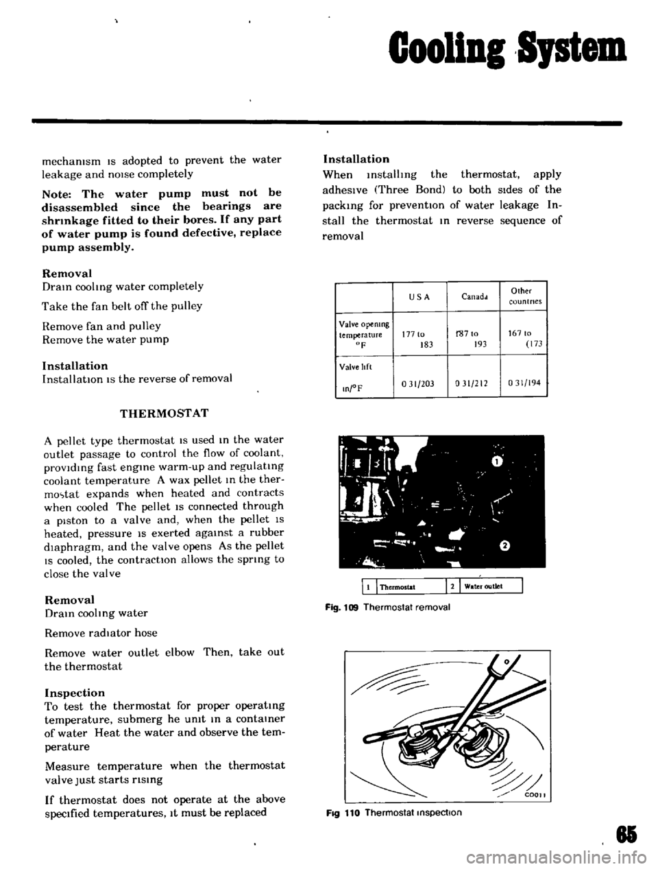
THERMOSTAT
A
pellet
type
thermostat
IS
used
m
the
water
outlet
passage
to
control
the
flow
of
coolant
provldmg
fast
engme
warm
up
and
regulatmg
coolant
temperature
A
wax
pellet
m
the
ther
mo
tat
expands
when
heated
and
contracts
when
cooled
The
pellet
IS
connected
through
a
piston
to
a
valve
and
when
the
pellet
IS
heated
pressure
IS
exerted
agamst
a
rubber
dIaphragm
and
the
valve
opens
As
the
pellet
IS
cooled
the
contractIOn
allows
the
sprmg
to
close
the
valve
Removal
Dram
coohng
water
Remove
radiator
hose
Remove
water
outlet
elbow
Then
take
out
the
thermostat
Inspection
To
test
the
thermostat
for
proper
operatmg
temperature
submerg
he
umt
m
a
contamer
of
water
Heat
the
water
and
observe
the
tem
perature
Measure
temperature
when
the
thermostat
valve
Just
starts
rlsmg
If
thermostat
does
not
operate
at
the
above
specIfied
temperatures
It
must
be
replaced
Installation
When
mstalhng
the
thermostat
apply
adheSIve
Three
Bond
to
both
SIdes
of
the
packmg
for
preventIOn
of
water
leakage
In
stall
the
thermostat
m
reverse
sequence
of
removal
USA
Canadd
Olher
coun
t
nes
Valve
opemng
temperature
177
to
r8710
16710
F
183
193
173
Valve
lIft
O
oF
031
203
031
212
031
194
WI
fL
g
0
I
l
1
L
JI
I
I
I
I
a
J
i
o
wa
r
outlet
EI
Thermostat
Fig
109
Thermostat
removal
FIQ
110
Thermostat
inspection
81
Page 62 of 136
Gooliol
SJstem
RADIATOR
The
radiator
IS
of
a
down
flow
type
w1th
an
ex
panslOn
tank
located
on
the
top
of
tube
sec
tlOn
Pressure
IS
applted
to
the
system
and
the
I
eltef
valve
Incorporated
In
the
radiator
filler
cap
controls
the
pressure
at
approximately
13
Ib
sq
In
Removal
DraIn
cooltng
water
DIsconnect
radiator
upper
hose
lower
hose
and
hose
to
the
reservOir
tank
Detach
the
radiator
assembly
by
removmg
SIX
fiXIng
bolts
Inspection
Check
for
water
leakage
and
cracks
USIng
a
cap
tester
If
such
defects
are
detected
repair
88
Fig
111
Radiator
removal
or
replace
the
radIator
assembly
Installation
InstallatIOn
IS
the
reverse
of
removal
Page 102 of 136

Bod
Work
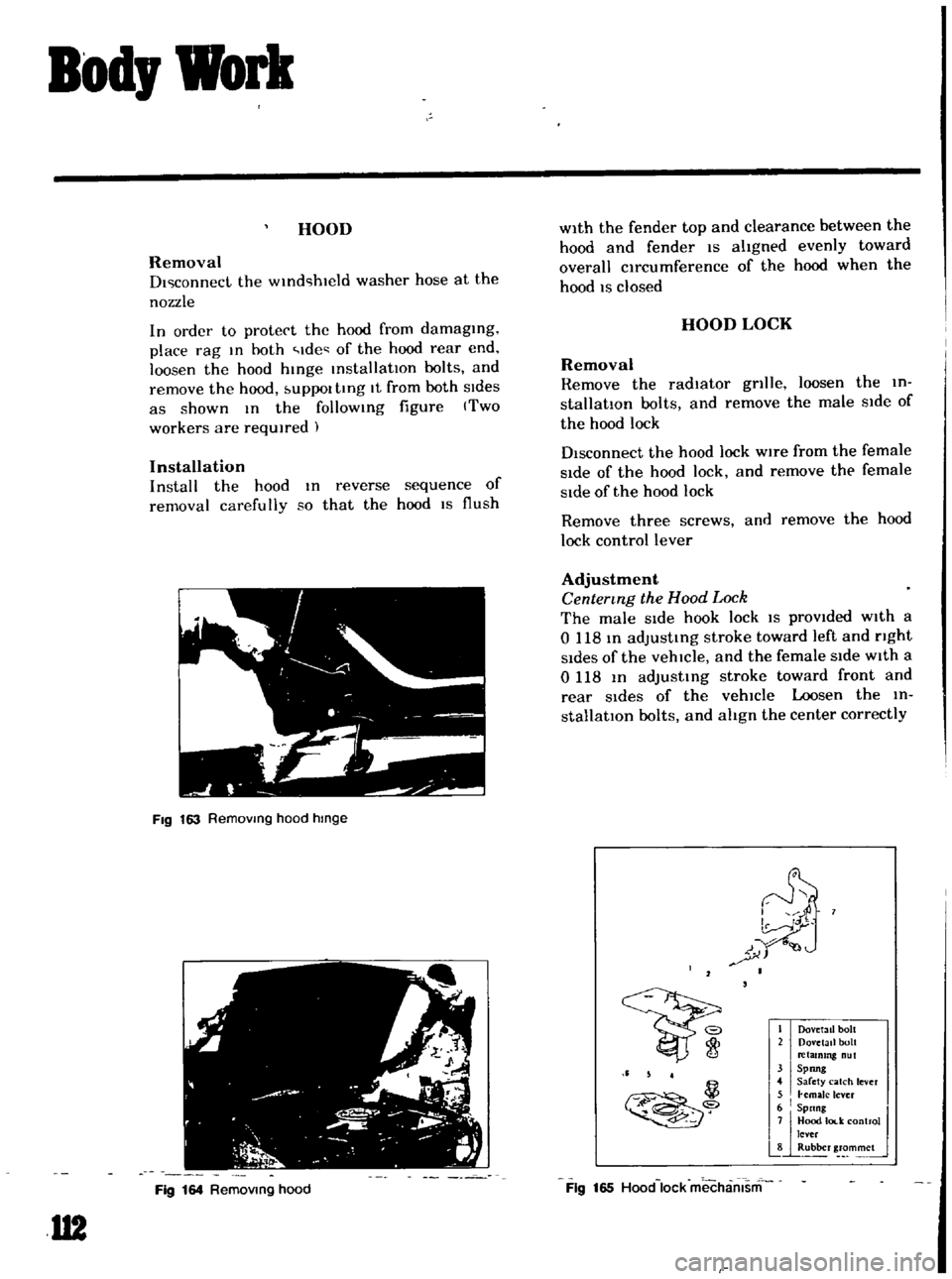
HOOD
Removal
DI
connect
the
WInd
hwld
washer
hose
at
the
nozzle
In
order
to
protect
the
hood
from
damaging
place
rag
In
hoth
Ide
of
the
hood
rear
end
loosen
the
hood
hinge
installatIOn
bolts
and
remove
the
hood
UPPOl
tIng
It
from
both
SIdes
as
shown
In
the
follOWing
figure
Two
workers
are
required
Installation
Install
the
hood
In
reverse
sequence
of
removal
carefully
so
that
the
hood
IS
flush
FIg
163
Removmg
hood
hmge
Fig
164
Removmg
hood
U2
with
the
fender
top
and
clearance
between
the
hood
and
fender
IS
aligned
evenly
toward
overall
circumference
of
the
hood
when
the
hood
IS
closed
HOOD
LOCK
Removal
Remove
the
radiator
gnlle
loosen
the
in
stallation
bolts
and
remove
the
male
Side
of
the
hood
lock
Disconnect
the
hood
lock
wire
from
the
female
Side
of
the
hood
lock
and
remove
the
female
Side
of
the
hood
lock
Remove
three
screws
and
remove
the
hood
lock
control
lever
Adjustment
Centermg
the
Hood
Lock
The
male
Side
hook
lock
IS
prOVided
with
a
o
118
In
adjusting
stroke
toward
left
and
nght
Sides
of
the
vehicle
and
the
female
SIde
with
a
0118
In
adjustIng
stroke
toward
front
and
rear
Sides
of
the
vehicle
Loosen
the
in
stallatIOn
bolts
and
align
the
center
correctly
I
Dov
tall
bolt
2
Dovetail
bolt
retammg
nut
31
Spong
4
Sarety
catch
lever
5
I
hmaJc
lever
6
Spnng
j
7JjHood
lod
control
lever
8
Rubber
grommet
Ii
5
4
il
Fig
165
Hood
lock
mechamsm
Page 128 of 136
1
It
t
ir
4
I
1
1
J
i
t
1
f
Ii
fj
A
l
1
t
i
I
J
1my
t
It
ff
r
car
k
t
f
11
v
1
t
t
COOLING
SYSTEM
0
JJ
DimenSIOns
of
radIator
core
Height
x
Width
x
Thickness
mm
m
330
x
344
x
32
13
0
x
135
x
I
26
Type
Corrugate
fm
type
Radiator
fm
spacmg
mm
m
2
5
0
098
RadIator
capacity
K
cat
hoC
335
Cap
workIng
pressure
kg
cm2
Ib
sq
In
09
t
0
I
13
t
14
Water
capacity
with
heater
e
US
qt
Imp
qt
49
S
v
6
471
i
t
fj
looIo
t
lk
i
J
l