Page 2 of 136

lI
I
DATSUN
1200
RANGE
1971
1973
MAINTENANCE
REPAIR
BY
DRAKE
AUTOMOTIVE
EDITORS
Quick
Referencelodel
MAINTENANCE
TUNE
UP
5
STEERING
89
ENGINEERING
13
REAR
DRIVE
ELECTRICAL
SYSTEM
35
SUSPENSION
93
IGNITION
SYSTEM
43
CLUTCH
99
FUEL
SYSTEM
49
TRANSMISSION
103
COOLING
SYSTEM
63
BODY
WORK
111
BRAKES
67
SPECIFICATIONS
129
FRONT
SUSPENSION
83
The
purpose
of
this
manual
IS
to
provide
the
automobile
owner
and
mechanic
with
a
reference
source
with
which
he
can
perform
normal
service
operations
We
endeavor
to
lOcorporate
the
latest
manufacturing
design
changes
and
up
to
date
specifications
at
the
time
of
publication
While
every
effort
IS
made
to
attain
accuracy
the
Publisher
cannot
be
held
responsible
for
manufacturing
changes
typographical
errors
or
omiSSions
Upon
compIling
the
information
contained
herein
we
have
tried
to
be
brief
and
Simple
relvlng
on
the
combination
of
photographs
Illustrations
and
text
to
make
thIS
manual
a
useful
tool
DRAKE
PUBLISHERS
INC
361
PARK
AVENUE
SOUTH
NEW
YORK
NY
10016
Page 5 of 136

labl8
of
Contents
Jets
60
FRONT
SUSPENSION
TlOuble
Shooting
60
f
DESCRIPTION
RECOMMENDATIONS
TROUBLE
SHOOTING
I
85
COOLING
SYSTEM
DESCRIPTION
64
STEERING
WATER
PUMP
64
Hemoval
65
DESCRIPTION
90
InstallatIOn
65
RECOMMENDATIONS
90
THERMOSTAT
65
TROUBLE
SHOOTING
91
Removal
65
InspectIOn
65
REAR
DRIVE
Installation
65
RADIATOR
66
SUSPENSION
Hemovdl
66
InspectIOn
66
REAR
AXLE
94
InstallatIOn
66
DIFFERENTIAL
94
REAR
SUSPENSION
95
REAR
SHOCK
ABSORBER
96
Replacement
96
BRAKES
InspectIOn
97
RECOMMENDATIONS
97
FRONT
DISC
BRAKE
68
BRAKE
PAD
68
Replacement
68
CLUTCH
InspectIOn
68
ReinstallatIOn
68
DESCRIPTION
CALIPER
70
CLUTCH
PEDAL
Removal
70
Removal
Disassembly
71
InspectIOn
InspectIOn
Repmr
71
ReinstallatIOn
Reassembly
72
Adjustment
ReinstallatIOn
74
CLUTCH
MASTER
CYLINDER
REAR
BRAKE
74
Removal
Hemoval
Dlsdssembly
74
DIsassembly
InspectIOn
75
InspectIOn
Reassembly
ReinstallatIOn
75
Reassembly
HAND
BRAKE
75
RemstallatlOn
Removal
75
BLEEDING
CLUTCH
SYSTEM
InspectIOn
76
RemstallatlOn
77
ADJUSTMENT
78
TRANSMISSION
Front
DI
c
Brake
78
Rear
Brake
78
4
SPEED
TRANSMISSION
Brake
Pedal
HeIght
78
3
SPEED
TRANSMISSION
Hand
Brake
79
TROUBLE
SHOOTING
BLEEPIN
HYD
AULIC
SYs
r
M
79
i
UIQM
ATJ
C
TRANSMJSSIQ
TROUBLE
SHOOTING
80
RECOMMENDATIONS
2
Page 8 of 136

ainteDaDee
TUDe
up
VAL
VE
CLEARANCES
Valve
clearance
adjustment
should
be
made
while
engme
IS
stationary
To
adjust
proceed
as
follows
Start
engme
and
run
It
until
It
IS
heated
to
operatIng
temperature
or
at
least
more
than
17S
of
engIne
011
temperature
then
stop
engIne
Rotate
crankshaft
to
bnng
No
1
cylInder
In
top
dead
center
on
ItS
compressIOn
stroke
Remove
valve
rocker
cover
to
gaIn
access
to
valve
operatIng
mechamsm
Adjust
valve
clearance
at
follOWing
four
pOints
while
engIne
IS
still
hot
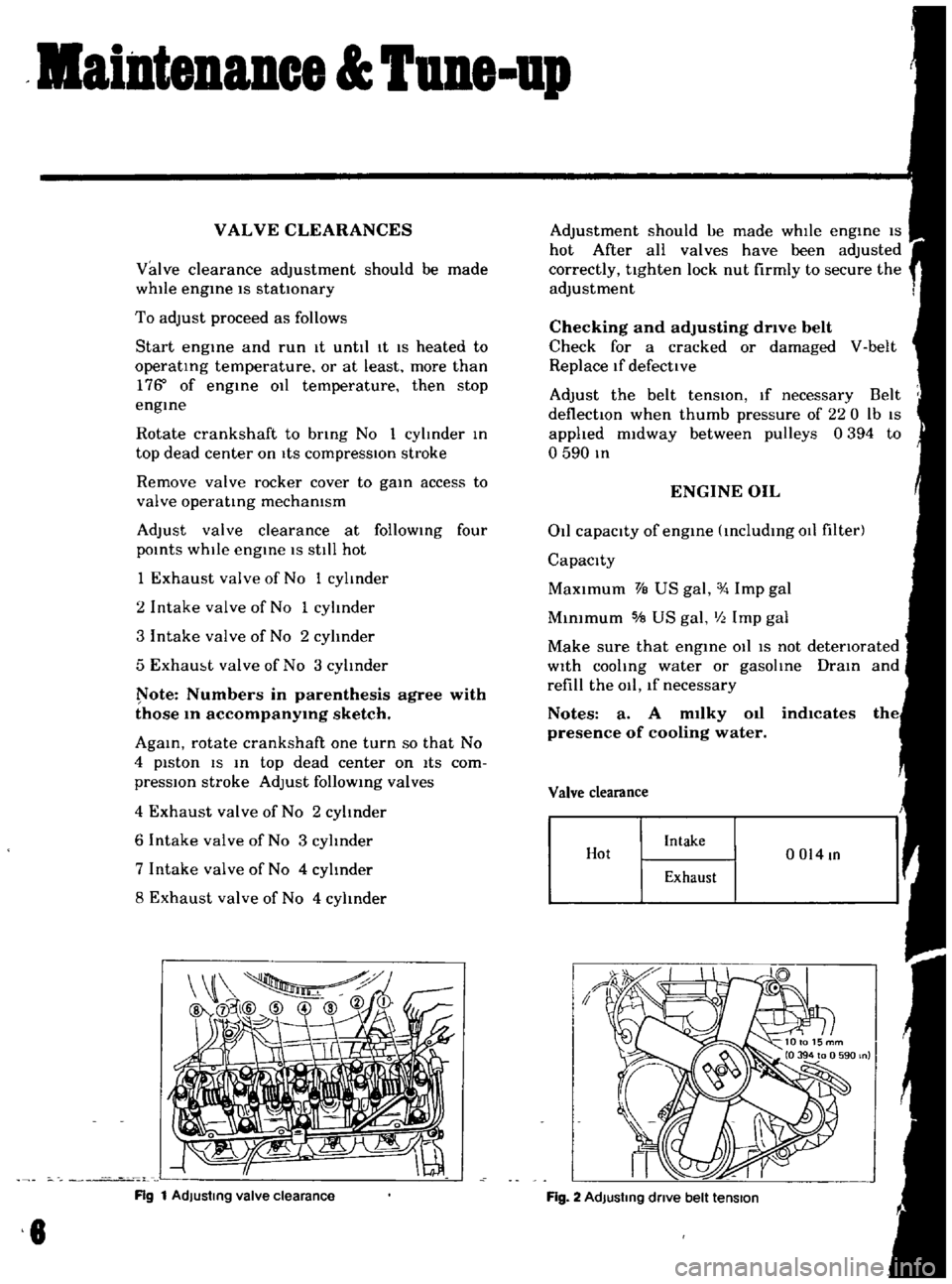
1
Exhaust
valve
of
No
1
cylinder
2
Intake
valve
of
No
1
cylinder
3
Intake
valve
of
No
2
cylinder
5
Exham
t
valve
of
No
3
cylInder
ote
Numbers
in
parenthesis
agree
with
those
10
accompanY1Og
sketch
AgaIn
rotate
crankshaft
one
turn
so
that
No
4
piston
IS
In
top
dead
center
on
ItS
com
pressIOn
stroke
Adjust
follOWIng
valves
4
Exhaust
valve
of
No
2
cylinder
6
Intake
valve
of
No
3
cylinder
7
Intake
valve
of
No
4
cylInder
8
Exhaust
valve
of
No
4
cylinder
Rg
1
AdJustmg
valve
clearance
8
Adjustment
should
ue
made
whIle
engIne
IS
hot
After
all
valves
have
been
adjusted
correctly
tighten
lock
nut
firmly
to
secure
the
adjustment
Checking
and
adjusting
drive
belt
Check
for
a
cracked
or
damaged
V
belt
Replace
If
defective
Adjust
the
belt
tenSIOn
If
necessary
Belt
deflectIOn
when
thumb
pressure
of
220
Ib
IS
applied
midway
between
pulleys
0394
to
o
590
In
ENGINE
OIL
011
capacity
of
engIne
IncludIng
011
filter
Capacity
MaXimum
VB
US
gal
Imp
gal
MInimum
5IB
US
gal
III
Imp
gal
Make
sure
that
engIne
011
IS
not
detenorated
With
cooling
water
or
gasolIne
DraIn
and
refill
the
011
lf
necessary
Notes
a
A
m1lky
011
indlcates
presence
of
cooling
water
Valve
clearance
Hot
Intake
0014
In
Exhaust
Fig
2
AdJustmg
dnve
belt
tension
Page 60 of 136
Cooling
Sptem
Fig
106
Coolmg
system
C0026
FIg
107
Water
pump
and
front
cover
FIg
1I1S
Water
pump
removal
DESCRIPTION
radiator
w1th
hIgh
coohng
efficiency
and
of
a
pellet
type
thermostat
The
coohng
system
IS
of
a
closed
pressure
type
With
hIgh
coolmg
capablhty
Coohng
water
WATER
PUMP
flowmg
through
resIstance
free
water
passages
m
the
cyhnder
head
and
cyhnder
The
water
pump
IS
a
centrifugal
type
water
block
IS
mamtamed
at
adequate
temperature
pum
WIth
an
alumlpum
d1e
cast
pump
body
range
at
allo
tlmes
by
means
of
an
ample
T
he
olute
chamber
IS
bUIlt
mto
the
front
capacIty
water
pump
of
a
corrugated
fin
type
cover
assembly
and
a
high
pressure
seahng
84
Page 128 of 136
1
It
t
ir
4
I
1
1
J
i
t
1
f
Ii
fj
A
l
1
t
i
I
J
1my
t
It
ff
r
car
k
t
f
11
v
1
t
t
COOLING
SYSTEM
0
JJ
DimenSIOns
of
radIator
core
Height
x
Width
x
Thickness
mm
m
330
x
344
x
32
13
0
x
135
x
I
26
Type
Corrugate
fm
type
Radiator
fm
spacmg
mm
m
2
5
0
098
RadIator
capacity
K
cat
hoC
335
Cap
workIng
pressure
kg
cm2
Ib
sq
In
09
t
0
I
13
t
14
Water
capacity
with
heater
e
US
qt
Imp
qt
49
S
v
6
471
i
t
fj
looIo
t
lk
i
J
l