1969 DATSUN B110 air condition
[x] Cancel search: air conditionPage 45 of 136
Icnition
Sptem
Ovcrhc
Jtmg
Norm
Jl
i
r
rJ
I
ttr
I
i
V
Carbon
fould
Fig
85
Spark
plug
Life
plug
heat
range
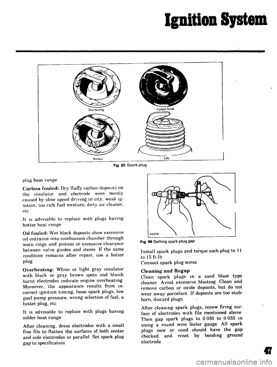
Carbon
fouled
Dry
fluffy
carbon
depo
lts
on
the
Insulator
and
electrode
were
mostly
caused
by
slow
speed
dnvlng
In
cIty
weak
Ig
nltlOn
too
nch
fuel
mixture
dirty
aIr
cleaner
etc
It
IS
advIsable
to
replace
WIth
plugs
havmg
hotter
heat
range
011
fouled
Wet
black
depoSits
show
excesSive
oIl
entrance
Into
combusllon
chamber
through
worn
rmgs
and
pIstons
or
excessIve
clearance
between
valve
gUIdes
and
stems
If
the
same
condition
remams
after
repair
use
a
hotter
plug
Overheatmg
WhIte
or
hght
gray
msulator
WIth
black
or
gray
brown
spots
and
blUIsh
burnt
electrodes
indIcate
engme
overheatIng
Moreover
th
e
appearance
results
from
in
correct
IgnitIon
tIming
loose
spark
plugs
low
guel
pump
pressure
wrong
selectIOn
of
fuel
a
hotter
plug
etc
It
IS
adVisable
to
replace
WIth
plugs
havmg
colder
heat
range
After
cleaning
dress
electrodes
With
a
small
fine
file
to
flatten
the
surfaces
of
both
center
and
Side
electrodes
In
parallel
Set
spark
plug
gap
to
specification
FIg
86
Settmg
spark
plug
gap
Install
spark
plugs
and
torque
each
plug
to
11
to
15
ft
Ib
Connect
spark
plug
wires
Cleaning
and
Regap
Clean
spark
plugs
In
a
sand
blast
type
cleaner
A
VOId
excessIve
blasting
Clean
and
remove
carbon
or
OXide
depoSits
but
do
not
wear
away
porcelain
If
depos1ts
are
too
stub
born
discard
plugs
After
cleaning
spark
plugs
renew
firing
sur
face
of
electrodes
With
file
mentioned
above
Then
gap
spark
plugs
to
0
030
to
0
035
In
uSing
a
round
wire
feeler
gauge
All
spark
plugs
new
or
used
should
have
the
gap
checked
and
reset
by
bending
ground
electrode
II
Page 48 of 136
Fuel
Sptem
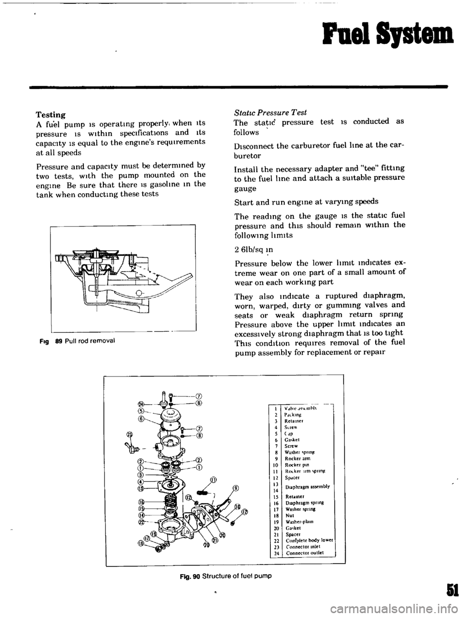
Testing
A
fuel
pump
IS
operatIng
properly
when
1tS
pressure
IS
Within
specifications
and
ItS
capacIty
IS
equal
to
the
engine
s
reqUIrements
at
all
speeds
Pressure
and
capacity
must
be
determined
by
two
tests
With
the
pump
mounted
on
the
engIne
Be
sure
that
there
IS
gasohne
m
the
tank
when
conductIng
these
tests
Fig
89
Pull
rod
removal
StatIc
Pressure
Test
The
static
pressure
test
IS
conducted
as
follows
Disconnect
the
carburetor
fuel
line
at
the
car
buretor
Install
the
necessary
adapter
and
tee
fitting
to
the
fuel
Ime
and
attach
a
SUitable
pressure
gauge
Start
and
run
engme
at
varymg
speeds
The
readIng
on
the
gauge
IS
the
static
fuel
pressure
and
thIS
should
remam
wlthm
the
follOWing
Itmlts
2
61b
sq
m
Pressure
below
the
lower
hmlt
IndlCates
ex
treme
wear
on
one
part
of
a
small
amount
of
wear
on
each
working
part
They
also
md1cate
a
ruptured
dIaphragm
worn
warped
dirty
or
gummmg
valves
and
seats
or
weak
dIaphragm
return
spring
Pressure
above
the
upper
hmlt
Indicates
an
excessIVely
strong
dIaphragm
that
IS
too
tight
ThIS
condItIOn
reqUIres
removal
of
the
fuel
pump
assembly
for
replacement
or
repair
I
V
lvc
llllh
2
PdlklOg
3
Retamer
4
Stre
5
p
6
Ga
ket
7
Screw
8
Washer
prln
9
Rocker
Jrm
10
Rocker
pm
II
Ro
ker
fm
pTln
12
Spdcer
13
Diaphragm
assembly
14
15
Retiuner
16
Diaphragm
sprtng
17
Washer
5PIlllg
18
Nul
19
Washer
plalO
20
Ga
ket
21
Spacer
22
Complete
body
lower
23
Connector
anlet
24
Connector
outlet
Fig
90
Structure
of
fuel
pump
51
Page 57 of 136
Fuel
SJstem
Check
float
needle
and
seat
for
wear
Replace
the
assembly
If
worn
Check
the
throttle
and
choke
bores
In
throttle
body
and
cover
castIng
for
wear
or
out
of
round
Inspect
Idle
adjustIng
needles
for
burrs
or
ndges
Replace
as
reqUIred
Inspect
gaskets
to
ensure
that
they
do
not
ap
pear
hard
or
bnttle
and
that
the
edges
are
not
turned
or
dIstorted
If
any
such
condItIOn
IS
detected
they
must
be
replaced
Check
filter
secreen
screen
for
cloggIng
Clean
and
If
It
IS
dIstorted
or
remaInS
plugged
replace
Check
cluster
for
loose
or
worn
parts
If
damage
or
Ioosene
s
eXists
replace
cluster
assembly
Check
the
hnkage
for
operatIng
condItion
Inspect
the
operatIOn
of
acceleratIng
pump
Pour
gasohne
Into
the
float
chamber
and
operate
the
throttle
hver
Check
conditIOn
of
gasohne
InjectIOn
from
the
acceleratIng
nozzle
Assembly
and
Installation
Assemble
and
Install
the
carburetor
In
I
everse
sequence
of
dIsassembly
and
removal
Replace
the
gaskets
If
necessary
When
dlsassembhng
and
reassembhng
the
In
terlock
hnk
and
related
components
be
careful
not
to
bend
or
deform
the
components
Reassembly
carefully
and
correctly
so
that
all
Interlock
hnks
operate
smoothly
Jets
The
carburetor
performance
depends
on
Jets
and
aIr
bleed
and
the
vehicle
emISSIOns
largely
depends
on
the
carburetor
performan
ce
That
IS
why
these
components
are
manufactured
WIth
utmost
care
To
clean
them
use
gasohne
and
blow
aIr
on
them
ChangIng
Jet
or
air
bleed
sIze
may
cause
III
vehICle
emIssIon
So
they
should
not
be
changed
theIr
numbers
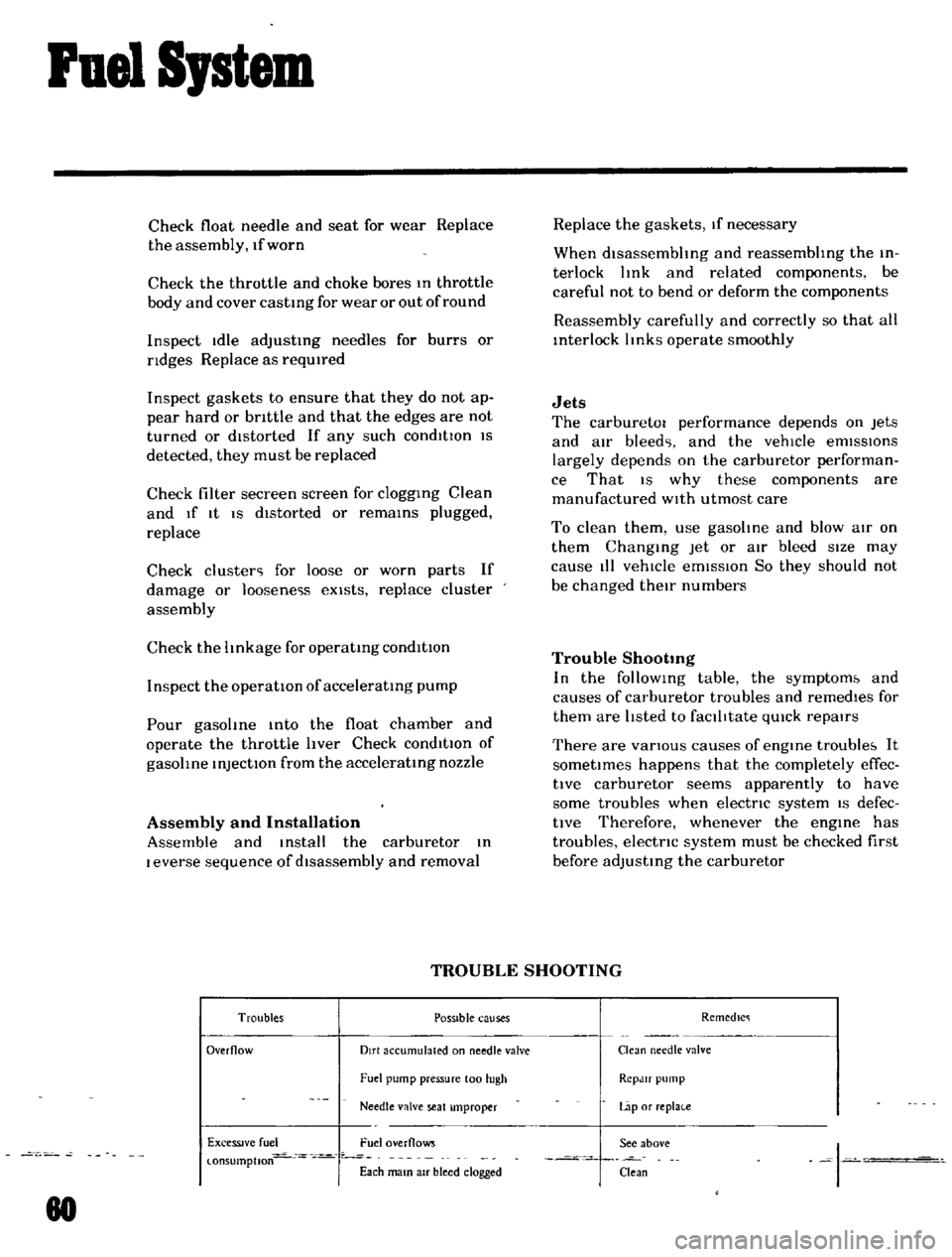
Trouble
Shootmg
In
the
follOWIng
table
the
symptom
and
causes
of
carburetor
troubles
and
remedIes
for
them
are
hsted
to
faclhtate
qUIck
repaIrs
There
are
vanous
causes
of
engIne
trouble
It
sometImes
happens
that
the
completely
effec
tlve
carburetor
seems
apparently
to
have
some
troubles
when
electnc
systern
IS
defec
tIve
Therefore
whenever
the
engIne
has
troubles
electnc
system
must
be
checked
first
before
adjusting
the
carburetor
TROUBLE
SHOOTING
Troubles
POSSible
causes
Remedlc
Overflow
Dirt
accumulated
on
needle
valve
Clean
needle
valve
Fuel
pump
pressure
100
hIgh
RCpJlf
pump
Needle
valve
seat
Improper
Lap
or
replai
e
ExceSSIve
fuel
Fuel
overflows
See
above
I
l
onsumptlon
Each
mam
aIr
bleed
clogged
Clean
80
Page 75 of 136
Brakes
Thoroughly
Wipe
the
bleeder
screw
and
from
any
mud
or
dust
present
so
that
the
outlet
hole
IS
free
from
foreign
matter
Attach
a
VInyl
hose
to
the
wheel
cyhnder
bleeder
screw
Dip
the
end
of
the
VInyl
hose
In
a
Jar
contaInIng
some
brake
flUId
Depress
the
brake
pedal
two
to
three
times
and
keep
the
pedal
fully
depressed
With
the
brake
pedal
fully
depressed
loosen
the
bleeder
screw
exhaust
air
and
rettghten
the
bleeder
screw
qUIckly
Return
the
brake
pedal
slowly
Repeat
the
operatIons
above
Air
WIll
no
longer
come
out
from
the
bleeder
screw
but
brake
flUId
comes
out
When
atr
stIll
eXists
In
brake
flUId
It
appears
whIte
due
to
aIr
bub
ble
Conduct
aIr
bleedIng
on
other
wheel
cyhnders
In
the
same
manner
Note
a
Check
the
reservoir
for
fluid
level
during
bleeding
operation
b
FlUid
withdrawn
in
the
operation
should
not
be
used
refilling
bleeding
again
for
c
When
the
master
cylinder
is
dIsassem
bled
or
replaced
conduct
air
bleeding
on
the
wheel
cylinder
which
is
located
most
near
the
master
cyhnder
d
Ordinarily
air
bleeding
is
performed
in
the
following
sequence
Rear
left
Rear
right
Front
left
Front
right
e
Do
not
return
the
brake
pedal
before
retightening
the
bleeder
screw
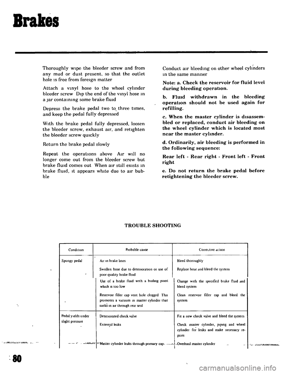
TROUBLE
SHOOTING
Condition
Probable
cause
Corretttve
dellon
Spongy
pedal
Au
In
brake
lines
Bleed
Ihoroughly
Swollen
hose
due
to
detenoratlOn
or
use
of
Replace
ho
e
md
bleed
the
system
poor
qualIty
brake
flUid
Use
of
a
brake
flu
d
wIth
a
bOilIng
pomt
Change
wIth
the
spectlied
brake
flUId
dnd
which
15
too
low
bleed
system
ReservOir
filler
cap
vent
hole
clogged
Tins
Clean
reserVOIr
filler
cap
and
bleed
the
promotes
a
Vdcuum
In
master
cylinder
that
system
suckS
In
air
through
rear
seal
Pedal
Yields
under
Detenorated
check
valve
Fit
a
new
check
valve
and
bleed
the
system
shght
pressure
ExterIlalleaks
Check
master
cyhnder
plpmg
and
wheel
cylInder
for
leaks
and
make
necessary
re
pairs
Master
cyhnder
leaks
through
pnmary
cap
Overhaul
master
cyhnder
80
Page 91 of 136
Clutch
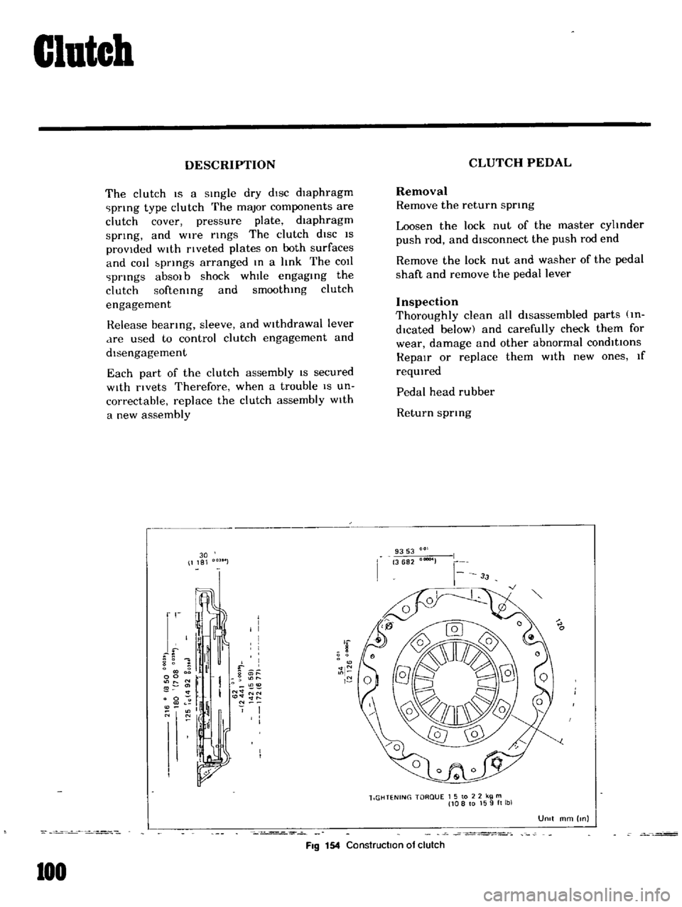
DESCRIPTION
The
clutch
IS
a
sIngle
dry
dIsc
diaphragm
prIng
type
clutch
The
major
components
are
clutch
cover
pressure
plate
diaphragm
sprIng
and
wire
rIngs
The
clutch
diSC
IS
provided
WIth
rIveted
plates
on
both
surfaces
and
cot
bprIngs
arranged
In
a
hnk
The
COIl
prIngs
absOl
b
shock
whIle
engagIng
the
clutch
softemng
and
smoothIng
clutch
engagement
Release
bearIng
sleeve
and
WIthdrawal
lever
dre
used
to
control
clutch
engagement
and
disengagement
Each
part
of
the
clutch
assembly
IS
secured
With
rivets
Therefore
when
a
trouble
IS
un
correctable
replace
the
clutch
assembly
With
a
new
assembly
30
1181
r
I
I
I
I
I
8
1
il
f
0
g
it
l
00
r
O
11
I
N
NN
0
to
lt
lt
ll
l
If
N
O
N
I
I
I
I
FIg
154
Construction
of
clutch
100
CLUTCH
PEDAL
Removal
Remove
the
return
sprmg
Loosen
the
lock
nut
of
the
master
cyhnder
push
rod
and
disconnect
the
push
rod
end
Remove
the
lock
nut
and
washer
of
the
pedal
shaft
and
remove
the
pedal
lever
Inspection
Thoroughly
clean
all
disassembled
parts
m
dlcated
below
and
carefully
check
them
for
wear
damage
and
other
abnormal
conditions
RepaIr
or
replace
them
With
new
ones
If
reqUIred
Pedal
head
rubber
Return
sprIng
9353
3682
00004
lIGHTENING
TORQUE
1
5
to
2
2
kg
m
108
to
159ft
lbl
UOIt
mm
Inl
Page 93 of 136
Clutch
Pedal
lever
bush
Fulcrum
pedal
pIn
etc
Remstallation
Reinstall
the
clutch
pedal
In
reverse
sequence
of
removal
Adjustment
Adjust
pedal
pad
heIght
to
565
In
Without
stopper
The
adjustment
IS
made
by
selectmg
and
applYIng
shlm
s
haVing
adequate
thIckness
Be
Ule
to
use
shIms
haVIng
same
thIckness
for
both
upper
and
lower
Next
adjust
the
pedal
stopper
properly
so
that
the
pedal
pad
height
IS
557
In
and
secure
the
pOSitIOn
WIth
lock
nut
Note
Make
sure
that
chaSSIS
grease
has
been
applied
to
the
CG
marked
portions
two
places
Grease
if
reqUired
CLUTCH
MASTER
CYLINDER
Removal
DIsconnect
the
push
rod
from
the
cleVIS
DIsconnect
the
clutch
lIne
from
the
master
cylinder
and
draIn
flUid
Remove
the
ecunng
bolts
and
remove
the
master
cyhnder
assembly
from
the
vehIcle
DIsassembly
Remove
the
filler
cap
and
draIn
flUId
Pull
back
the
dust
cover
and
remove
the
snap
rIng
The
stopper
push
rod
pIston
assembly
pnmary
cup
and
return
sptlng
assembly
can
be
removed
Inspection
Thoroughly
clean
all
parts
With
brake
flUId
before
InspectIOn
Check
the
cyhnder
and
piston
for
uneven
wear
or
damage
Replace
If
required
When
clearance
between
the
cylinder
and
pIston
IS
more
than
O
0059
In
replace
the
cyhnder
102
Replace
the
pIston
cup
pnmanly
whenever
the
master
cyhnder
IS
dIsassembled
It
must
also
be
replaced
when
wear
or
deformatIOn
due
to
fatIgue
or
damage
IS
found
Check
the
dust
cover
OIl
reservOIr
filler
cap
and
clutch
lIne
for
damage
or
deformatIOn
If
abnormal
condItIOn
IS
found
replace
With
new
one
Reassembly
Reassemble
the
master
cylInder
assembly
In
reverse
sequence
of
dIsassembly
notIng
the
follOWIng
matters
The
pIston
cup
should
be
soaked
In
brake
flUId
before
reassembly
Install
the
pIston
cup
carefully
so
that
It
IS
correctly
faced
Apply
brake
flUId
suffiCIently
to
the
cyhnder
and
pIston
and
assemble
them
Reinstallation
ReInstall
the
master
cyhnder
assembly
In
reverse
sequence
of
removal
and
adjust
as
follows
Adjust
the
pedal
heIght
by
changmg
the
push
rod
length
Bleed
air
out
of
the
hydrauhc
system
BLEEDING
CLUTCH
SYSTEM
Remove
the
bleed
screw
dust
cap
from
the
operatIng
cyhnder
Open
the
bleed
screw
approximately
three
quarters
of
a
turn
Attach
a
tube
Immer
SIng
the
open
end
mto
a
clean
contaIner
which
contaInS
a
small
amount
of
brake
flUId
Fill
the
master
cyhnder
reservOIr
With
the
recommended
flUId
Depress
the
clutch
pedal
qUIckly
while
keepIng
It
down
retighten
the
bleed
screw
and
allow
It
to
return
slowly
Repeat
thiS
pumpIng
actIOn
unttl
the
flUId
entenng
the
contaIner
IS
free
from
air
bubbles
Screw
up
the
bleed
screw
on
a
down
stroke
of
the
pedal
remove
the
bleec
t1
1
nd
rel1lace
the
dust
cap
Page 111 of 136
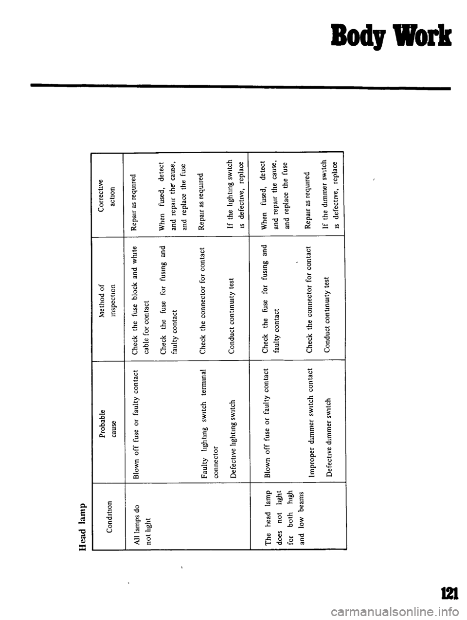
llead
anW
M
ethOd
of
Inspection
Probable
cause
Check
the
fuse
block
and
wlute
cable
for
contact
CondItiOn
Blown
off
fuse
or
faulty
contact
Check
the
fuse
for
fusIng
and
faulty
contact
An
lamps
do
not
hght
Faulty
hghtlng
sWItch
termInal
connector
Check
the
connector
for
contact
Conduct
continUIty
test
Defective
hghtlng
sWItch
Check
the
fuse
for
fusIng
and
faulty
contact
1h
1M
BI
m
off
CO
does
not
hght
for
both
high
and
loW
beams
Check
the
connector
for
contact
lmproper
dImmer
sWitch
contact
DefectIve
dImmer
sWitch
Conduct
contlnu
ty
test
Correctwe
ac
tlon
RepaIr
as
requtred
When
fused
detect
and
repaH
the
cause
and
replace
the
fuse
RepaIr
as
requHed
If
the
lighting
SWitch
IS
defectWe
replace
When
fused
detect
and
repair
the
cause
and
replace
the
fuse
RepaIr
as
requned
I
f
If
the
dImmer
sWitch
S
defectWe
replace
Page 112 of 136
a
f
1
I
I
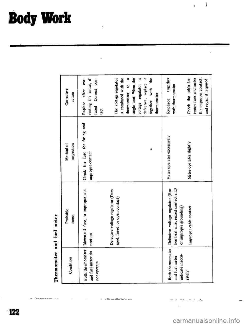
Thermometer
and
fuel
meter
condition
Probable
cause
Both
thermometer
Blov
U
off
fuse
or
Improper
con
and
fuel
meter
do
nectlOn
not
operate
r
II
1
Both
thermometer
and
fuel
meter
mdlcate
Inaccu
rately
Defec
IVe
voltage
regulator
Dam
aged
fused
or
open
contact
DefectIVe
voltage
regulator
Bro
ken
heat
Wire
seized
contact
and
or
Improper
grounding
lmproper
cable
contact
MethOd
of
lnspectlon
Check
the
fuse
for
fUSing
and
Improper
contact
Meter
operates
excessIVelY
Meter
operates
shghtly
o
a
t
Correctl
le
actlon
Replace
after
cor
rectiUg
the
cause
If
fused
Correct
con
tact
The
voltage
regulator
IS
combmed
With
the
thermometer
to
a
smgle
unit
When
the
voltage
regulator
IS
defectlve
replace
It
together
With
the
thermometer
Replace
together
With
thermometer
Check
the
cable
be
twee
l
fuse
and
meter
for
unproper
contact
and
repair
If
requlted