1969 DATSUN B110 clutch
[x] Cancel search: clutchPage 2 of 136
lI
I
DATSUN
1200
RANGE
1971
1973
MAINTENANCE
REPAIR
BY
DRAKE
AUTOMOTIVE
EDITORS
Quick
Referencelodel
MAINTENANCE
TUNE
UP
5
STEERING
89
ENGINEERING
13
REAR
DRIVE
ELECTRICAL
SYSTEM
35
SUSPENSION
93
IGNITION
SYSTEM
43
CLUTCH
99
FUEL
SYSTEM
49
TRANSMISSION
103
COOLING
SYSTEM
63
BODY
WORK
111
BRAKES
67
SPECIFICATIONS
129
FRONT
SUSPENSION
83
The
purpose
of
this
manual
IS
to
provide
the
automobile
owner
and
mechanic
with
a
reference
source
with
which
he
can
perform
normal
service
operations
We
endeavor
to
lOcorporate
the
latest
manufacturing
design
changes
and
up
to
date
specifications
at
the
time
of
publication
While
every
effort
IS
made
to
attain
accuracy
the
Publisher
cannot
be
held
responsible
for
manufacturing
changes
typographical
errors
or
omiSSions
Upon
compIling
the
information
contained
herein
we
have
tried
to
be
brief
and
Simple
relvlng
on
the
combination
of
photographs
Illustrations
and
text
to
make
thIS
manual
a
useful
tool
DRAKE
PUBLISHERS
INC
361
PARK
AVENUE
SOUTH
NEW
YORK
NY
10016
Page 5 of 136
labl8
of
Contents
Jets
60
FRONT
SUSPENSION
TlOuble
Shooting
60
f
DESCRIPTION
RECOMMENDATIONS
TROUBLE
SHOOTING
I
85
COOLING
SYSTEM
DESCRIPTION
64
STEERING
WATER
PUMP
64
Hemoval
65
DESCRIPTION
90
InstallatIOn
65
RECOMMENDATIONS
90
THERMOSTAT
65
TROUBLE
SHOOTING
91
Removal
65
InspectIOn
65
REAR
DRIVE
Installation
65
RADIATOR
66
SUSPENSION
Hemovdl
66
InspectIOn
66
REAR
AXLE
94
InstallatIOn
66
DIFFERENTIAL
94
REAR
SUSPENSION
95
REAR
SHOCK
ABSORBER
96
Replacement
96
BRAKES
InspectIOn
97
RECOMMENDATIONS
97
FRONT
DISC
BRAKE
68
BRAKE
PAD
68
Replacement
68
CLUTCH
InspectIOn
68
ReinstallatIOn
68
DESCRIPTION
CALIPER
70
CLUTCH
PEDAL
Removal
70
Removal
Disassembly
71
InspectIOn
InspectIOn
Repmr
71
ReinstallatIOn
Reassembly
72
Adjustment
ReinstallatIOn
74
CLUTCH
MASTER
CYLINDER
REAR
BRAKE
74
Removal
Hemoval
Dlsdssembly
74
DIsassembly
InspectIOn
75
InspectIOn
Reassembly
ReinstallatIOn
75
Reassembly
HAND
BRAKE
75
RemstallatlOn
Removal
75
BLEEDING
CLUTCH
SYSTEM
InspectIOn
76
RemstallatlOn
77
ADJUSTMENT
78
TRANSMISSION
Front
DI
c
Brake
78
Rear
Brake
78
4
SPEED
TRANSMISSION
Brake
Pedal
HeIght
78
3
SPEED
TRANSMISSION
Hand
Brake
79
TROUBLE
SHOOTING
BLEEPIN
HYD
AULIC
SYs
r
M
79
i
UIQM
ATJ
C
TRANSMJSSIQ
TROUBLE
SHOOTING
80
RECOMMENDATIONS
2
Page 6 of 136

fable
of
Contents
BODY
WORK
SPECIFICATIONS
I
HOOD
112
SERVICE
DATA
130
Removal
112
ENGINE
134
InstallatIOn
112
General
SpeCificatIOn
134
HOOD
LOCK
112
Tlghtemng
Torque
134
Removal
112
SpeCIficatIOn
135
Adjustment
112
Coohng
System
139
LubncatlOn
114
Fuel
System
140
TRUNK
LID
LOCK
116
Starter
142
Removal
116
Alternator
143
Adjustment
116
Regulator
144
TRUNK
LID
TORSION
BAR
116
Dlstnbutor
145
DOOR
CONSTRUCTION
117
IgnItIOn
Cot
145
WIRING
DIAGRAMS
118
CLUTCH
146
BULB
SPECIFICATIONS
120
NOTES
174
HEADLAMP
121
THERMOMETER
AND
FUEL
METER
122
OIL
PRESSURE
AND
IGNITION
WARNING
LAMPS
126
I
I
t
I
3
Page 15 of 136
Bngine
WIres
for
accelerator
and
choke
The
operatIOn
Will
be
carned
out
more
easily
by
removing
the
a1r
cleaner
Lift
up
the
engine
toward
the
front
INST
ALLA
TION
Install
the
engine
In
reverse
sequence
of
removal
Disconnecting
clutch
wire
on
nght
hand
dnve
model
On
left
hand
dnve
model
disconnect
hydraulIc
line
from
the
clutch
slave
cylInder
DIsconnect
the
clutch
WIre
at
the
JXlrtlOn
of
the
wIthdrawal
lever
Remove
the
exhaust
front
tube
Disconnect
the
the
cable
to
the
back
up
lamp
SWItch
D1sconnect
the
speedometer
cable
Remove
the
propeller
shaft
Remove
four
bolts
used
In
the
differential
carner
SIde
and
Withdraw
the
propeller
shaft
Remove
the
shift
lever
Model
With
remote
control
shIft
lever
Disconnect
the
remote
control
rod
at
the
JXlr
tlOn
of
transmiSSIOn
outer
lever
and
remove
the
remote
control
rod
Model
With
floor
Sh1ft
lever
Remove
the
boot
WIthdraw
the
lock
pin
and
remove
the
lever
The
operatIOn
IS
carned
out
In
the
passenger
compartment
Model
With
automatic
transmiSSIOn
Remove
pinS
from
both
ends
of
the
cross
shaft
and
remove
the
shIft
rod
Suspend
the
engine
With
wire
Remove
the
front
engine
mounting
installation
nuts
Remove
the
rear
engine
mounting
installation
nuts
When
removing
the
engine
mounting
in
stallation
nuts
be
sure
to
apply
a
Jack
beneath
the
transmiSSIOn
CLEANING
AND
INSPECTION
Clean
the
engine
thoroughly
before
disassem
bly
Before
cleaning
the
engine
remove
the
l
electncal
parts
and
plug
up
the
carburetor
air
horn
to
aVOid
intrusIOn
of
foreign
matter
The
engine
extenor
Check
the
covers
and
bolts
for
breakage
rust
damage
and
loss
CylInder
block
Check
thoroughly
the
water
Jacket
for
cracks
and
breakage
Clutch
hOUSing
Check
for
cracks
011
pan
Check
for
excessive
rust
DISASSEMBLY
Mount
engine
assembly
on
engine
stand
Remove
the
engine
mounting
bracket
R
H
Side
Install
the
engine
attachment
Mount
the
engine
on
the
stand
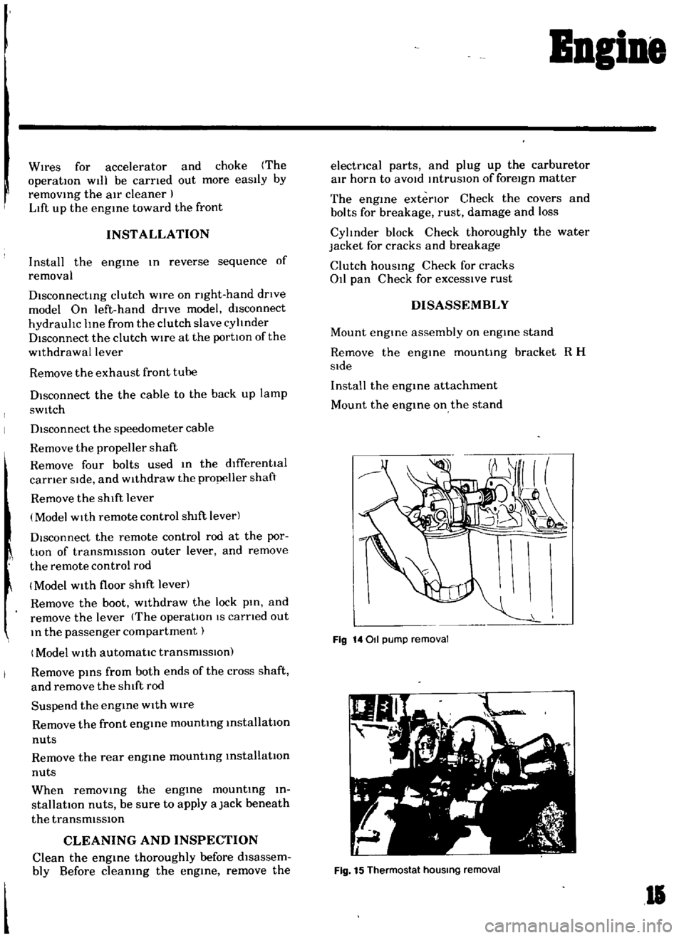
Fig
14011
pump
removal
Fig
15
Thermostat
hOUSing
removal
II
Page 25 of 136
Ingine
1
Cut
a
plastIgage
to
the
wIdth
of
the
bearing
and
place
It
m
parallel
with
the
crank
pm
gettmg
clear
of
the
011
hole
Install
the
cap
on
the
assembly
and
tighten
them
together
with
the
specified
torque
Tlghtentng
torque
36
to
43
ft
lb
Note
Be
sure
not
to
turn
the
crankshaft
when
the
plastIgage
is
Inserted
Remove
the
cap
and
measure
wIdth
of
the
plastlgage
at
Its
widest
part
wIth
the
scale
printed
tn
the
plastIgage
envelope
Crankshaft
Sprocket
and
Camshaft
Sprocket
Check
tooth
surfaces
for
flaws
and
wears
Replace
defective
sprocket
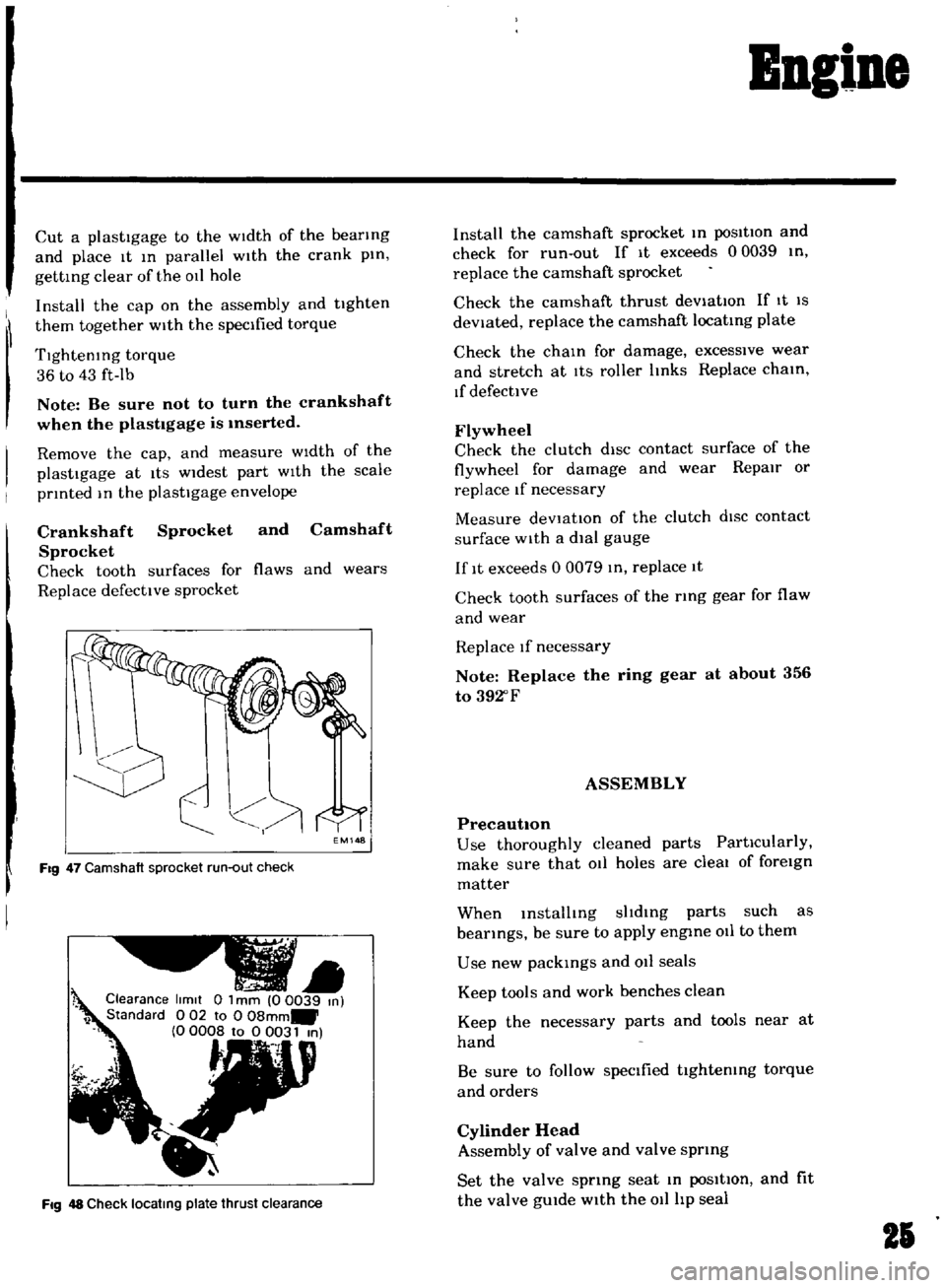
EM148
Fig
47
Camshaft
sprocket
run
out
check
Clearance
limit
0
1
mm
00039
m
1
Standard
0
02
to
0
08mm
0
0008
to
0
0031
m
t
Fig
48
Check
locatmg
plate
thrust
clearance
Install
the
camshaft
sprocket
m
posItion
and
check
for
run
out
If
It
exceeds
00039
tn
replace
the
camshaft
sprocket
Check
the
camshaft
thrust
deViatIOn
If
It
IS
deViated
replace
the
camshaft
locatmg
plate
Check
the
cham
for
damage
excessive
wear
and
stretch
at
ItS
roller
Imks
Replace
cham
If
defective
Flywheel
Check
the
clutch
diSC
contact
surface
of
the
flywheel
for
damage
and
wear
Repair
or
replace
If
necessary
Measure
deVtat10n
of
the
clutch
dISC
contact
surface
with
a
dial
gauge
If
It
exceeds
0
0079
m
replace
1t
Check
tooth
surfaces
of
the
ring
gear
for
flaw
and
wear
Replace
If
necessary
Note
Replace
the
ring
gear
at
about
356
to
392
F
ASSEMBLY
PrecautIOn
Use
thoroughly
cleaned
parts
PartIcularly
make
sure
that
011
holes
are
cleal
of
foreign
matter
When
mstalltng
sltdmg
parts
such
as
bearings
be
sure
to
apply
engme
011
to
them
Use
new
packmgs
and
011
seals
Keep
tools
and
work
benches
clean
Keep
the
necessary
parts
and
tools
near
at
hand
Be
sure
to
follow
specified
tIghtemng
torque
and
orders
Cylinder
Head
Assembly
of
valve
and
valve
sprmg
Set
the
valve
sprmg
seat
m
poSItIon
and
fit
the
valve
gUIde
with
the
011
hp
seal
21
Page 32 of 136
BBgiBe
Fig
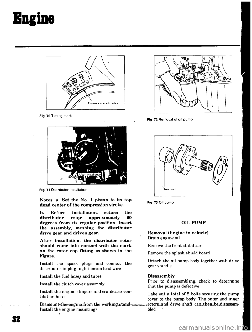
70
Tlmmg
mark
Fig
71
Dlstnbutor
mstallatlon
Notes
a
Set
the
No
1
piston
to
its
top
dead
center
of
the
compression
stroke
b
Before
installation
return
the
distributor
rotqr
approximately
60
degrees
from
Its
regular
position
Insert
the
assembly
meshing
the
distributor
drive
gear
and
driven
gear
After
installation
the
distributor
rotor
should
come
into
contact
wIth
the
mark
on
the
rotor
cap
fittmg
as
shown
in
the
Figure
Install
the
spark
plugs
and
connect
the
distrIbutor
to
plug
high
tensIOn
lead
wire
Install
the
fuel
hoses
and
tubes
Install
the
clutch
cover
assembly
Install
the
engme
shngers
and
crankcase
ven
tilatIOn
hose
Fig
72
Removal
of
011
pump
TrochoId
Fig
73011
pump
OIL
PUMP
Removal
Engine
in
vehlCIe
Dram
engme
OIl
Remove
the
front
stabilIzer
Remove
the
splash
shield
board
Detach
the
011
pump
body
together
with
drIve
gear
spmdle
Disassembly
PrIor
to
dlsassembhng
check
to
determme
that
the
pump
IS
defective
Take
out
a
total
of
2
bolts
securmg
the
pump
cover
to
the
pump
body
The
outer
and
mner
Dlsmount
the
engme
from
the
workmg
stand
rotors
and
drive
shaft
can
then
be
dlsassem
Install
the
engme
mountmgs
bled
32
Page 36 of 136
B1eetrical
Iptem
Removal
DIsconnect
the
battery
ground
cable
Disconnect
the
black
and
yellow
wIre
from
the
magnetic
sWitch
termmal
and
black
battery
cable
from
the
battery
termmal
Remove
two
bolts
used
to
secure
the
startmg
motor
on
the
clutch
housing
Pull
the
starter
assembly
forward
and
remove
the
starting
motor
Installation
InstallatlOn
IS
the
reversal
of
removal
Removal
Disconnect
the
negatIve
battery
termmal
DIsconnect
two
lead
wires
and
connector
from
the
alternator
Loosen
the
adjusting
bolt
Remove
the
alternator
drIve
belt
Remove
the
alternator
installation
bolt
Dismount
the
alternator
from
the
vehIcle
Installation
InstallatlOn
1S
the
reverse
of
removal
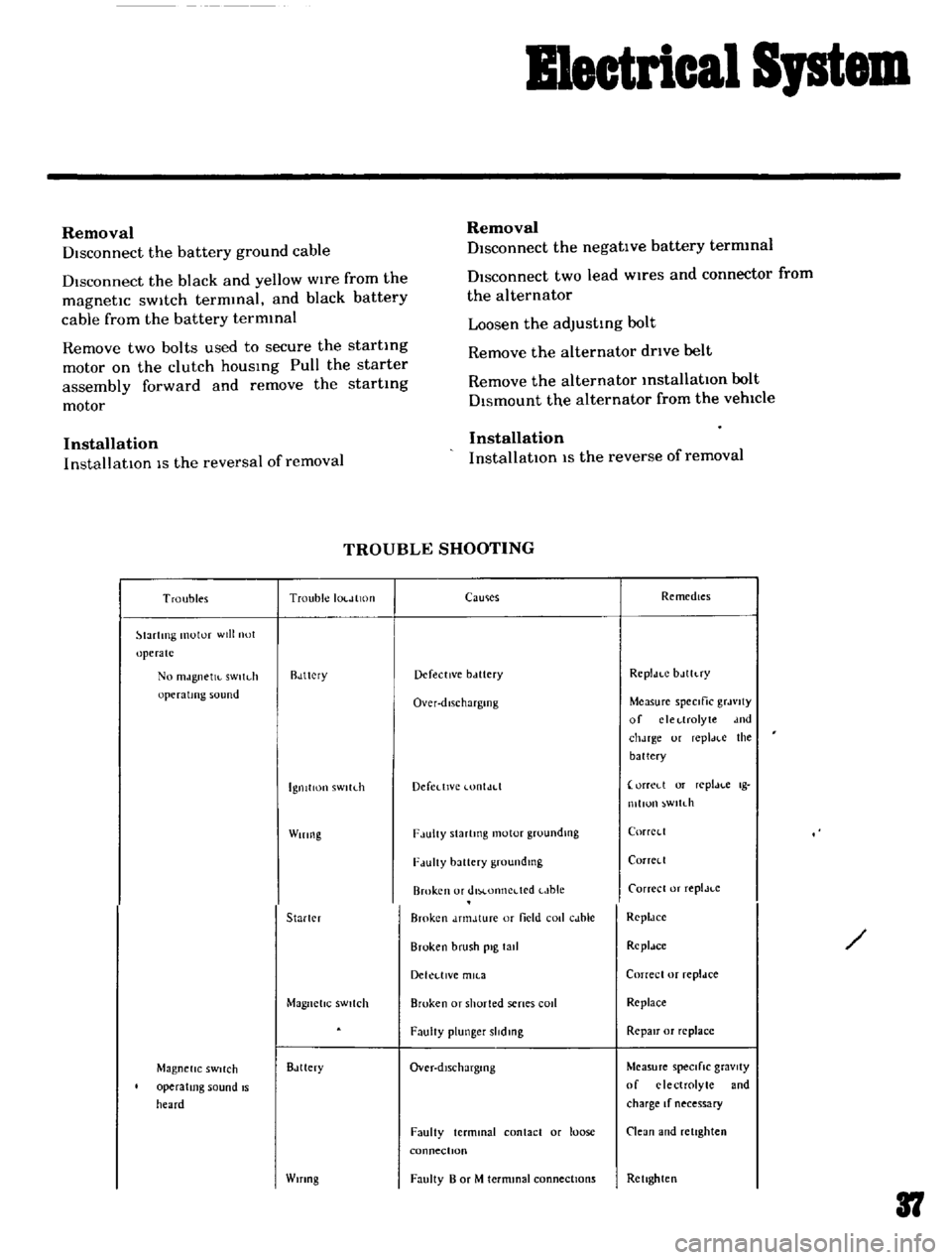
TROUBLE
SHOOTING
Troubles
Trouble
IOl
JlltHI
lartlTlg
motor
will
not
operate
No
mJgnetJl
sWltdl
operating
sound
Rdttcry
IgnitIon
sWltLh
Wiring
Starler
Magnetic
SWitch
Magnetic
SWitch
operating
sound
IS
heard
Bdttery
Wifing
CaUlies
Remedies
Defective
bclttery
Rcpldt
C
bJlh
ry
Over
dlschargmg
Measure
speCific
grJvlty
of
clcl
lrolyte
dnd
chJrge
ur
repl
H
e
the
battery
Defedlvc
lontJd
orreLl
or
replJl
c
Ig
mllun
wltdl
F
lulty
Slartmg
motor
groundlllg
CorrCl
l
F
lUlty
battery
groundmg
Corrcll
Broken
or
dlM
onncdcd
t
Jble
Carrece
or
replJt
c
Broken
dnnJture
or
field
coli
cJble
RcpldCC
Broken
brush
pig
tall
Rcpldce
Dekl
llVe
mll
3
Correcl
or
repldce
Broken
or
shorted
senes
cod
Replace
FaulIy
plunger
slidmg
RepaIr
or
replace
Over
dlschargmg
Measure
speCifiC
gravity
of
electrolyte
and
charge
If
necessary
Faulty
terminal
contact
or
loose
connectIOn
Clean
and
retighten
Faulty
B
or
M
termmal
connections
Rellghten
37
Page 91 of 136
Clutch
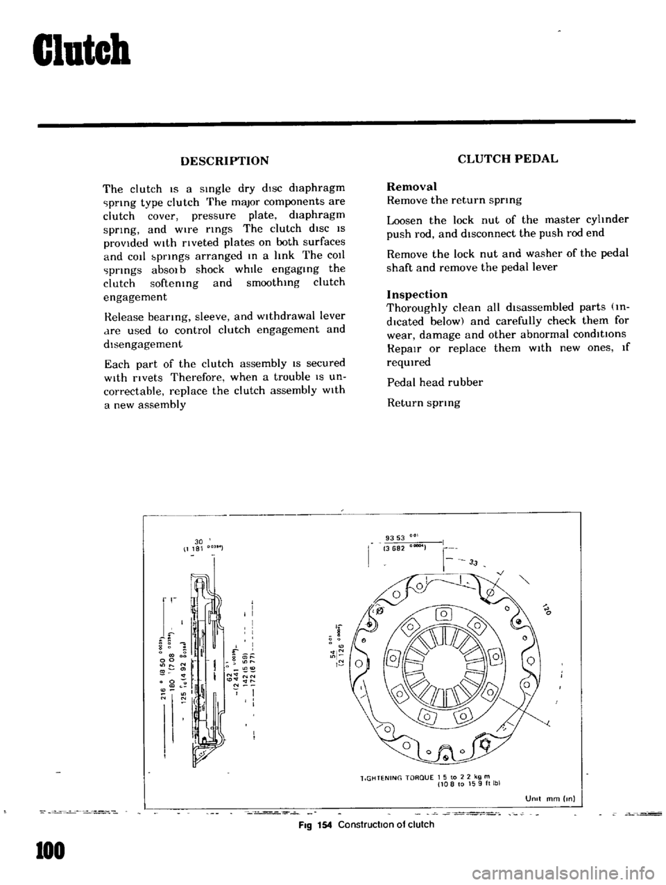
DESCRIPTION
The
clutch
IS
a
sIngle
dry
dIsc
diaphragm
prIng
type
clutch
The
major
components
are
clutch
cover
pressure
plate
diaphragm
sprIng
and
wire
rIngs
The
clutch
diSC
IS
provided
WIth
rIveted
plates
on
both
surfaces
and
cot
bprIngs
arranged
In
a
hnk
The
COIl
prIngs
absOl
b
shock
whIle
engagIng
the
clutch
softemng
and
smoothIng
clutch
engagement
Release
bearIng
sleeve
and
WIthdrawal
lever
dre
used
to
control
clutch
engagement
and
disengagement
Each
part
of
the
clutch
assembly
IS
secured
With
rivets
Therefore
when
a
trouble
IS
un
correctable
replace
the
clutch
assembly
With
a
new
assembly
30
1181
r
I
I
I
I
I
8
1
il
f
0
g
it
l
00
r
O
11
I
N
NN
0
to
lt
lt
ll
l
If
N
O
N
I
I
I
I
FIg
154
Construction
of
clutch
100
CLUTCH
PEDAL
Removal
Remove
the
return
sprmg
Loosen
the
lock
nut
of
the
master
cyhnder
push
rod
and
disconnect
the
push
rod
end
Remove
the
lock
nut
and
washer
of
the
pedal
shaft
and
remove
the
pedal
lever
Inspection
Thoroughly
clean
all
disassembled
parts
m
dlcated
below
and
carefully
check
them
for
wear
damage
and
other
abnormal
conditions
RepaIr
or
replace
them
With
new
ones
If
reqUIred
Pedal
head
rubber
Return
sprIng
9353
3682
00004
lIGHTENING
TORQUE
1
5
to
2
2
kg
m
108
to
159ft
lbl
UOIt
mm
Inl