1969 DATSUN B110 light
[x] Cancel search: lightPage 11 of 136
l
aiDteDaDce
UDe
up
Install
a
timing
lIght
on
No
1
cyhnder
spark
plug
WIre
and
Install
a
tachometer
Set
Idhng
ipeed
to
approximately
800
rpm
Check
19mtlOn
tImmg
If
It
IS
50BTDC
Before
Top
of
Dead
Center
by
the
use
of
tlmmg
hght
If
necessary
adjust
It
as
follows
Loosen
iet
screw
to
such
an
extent
that
dlstnbutor
can
be
moved
by
hand
AdJu
it
IgmtlOn
tIming
to
50BTDC
Lock
dlstnbutor
set
screw
and
make
sure
that
tlmmg
IS
correct
IgnitIOn
tImmg
degreel
50
B
T
DC
Distributor
Breaker
Point
Check
dlstnbutor
breaker
pomts
for
abnormal
pItting
and
wear
Replace
If
necessary
Make
wre
they
are
In
correct
ahgnment
for
full
con
tact
and
that
pOint
dwell
and
gap
are
correct
Clean
and
apply
dlstnbutor
grease
to
cam
and
WIck
Note
Do
not
apply
grease
excessively
Dl
tI
IbutOl
POint
gap
0
018
to
0
022
In
Dwell
angle
49
to
55
degrees
Condenser
Clean
outlet
of
condenser
lead
WIre
and
check
for
loose
set
screw
RetIghten
If
necessary
Check
condenber
capacIty
With
a
capacity
meter
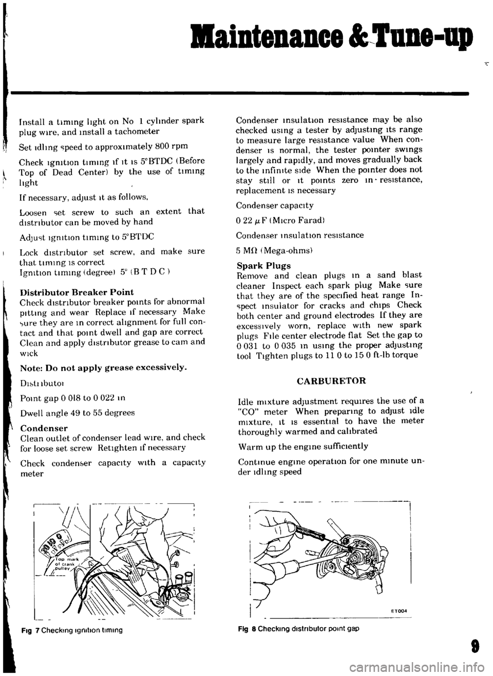
Fig
7
Checking
Igmllon
timing
Condenser
msulatlOn
resistance
may
be
also
checked
usmg
a
tester
by
adjusting
ItS
range
to
measure
large
resIstance
value
When
con
denser
IS
normal
the
tester
pomter
swmgs
largely
and
rapidly
and
moves
gradually
back
to
the
Infimte
SIde
When
the
pomter
does
not
stay
still
or
It
pomts
zero
m
reSIstance
replacement
IS
necessary
Condenser
capacIty
022
J
F
MIcro
Farad
Condenser
InsulatIOn
resIstance
5
Mn
Mega
ohms
Spark
Plugs
Remove
and
clean
plugs
In
a
sand
blast
cleaner
Inspect
each
spark
plug
Make
iure
that
they
are
of
the
specified
heat
range
In
ipect
msulator
for
cracks
and
chIps
Check
both
center
and
ground
electrodes
If
they
are
excessIVely
worn
replace
WIth
new
spark
plugs
File
center
electrode
flat
Set
the
gap
to
0031
to
0035
m
USIng
the
proper
adjustIng
tool
Tighten
plugs
to
11
0
to
150
ft
Ib
torque
CARBURETOR
Idle
mixture
adjustment
requIres
the
use
of
a
CO
meter
When
preparIng
to
adjust
Idle
mixture
It
IS
essential
to
have
the
meter
thoroughly
warmed
and
cahbrated
Warm
up
the
engme
suffiCiently
ContInue
engIne
operatIOn
for
one
mmute
un
der
ldhng
speed
I
i
I
I
I
I
I
I
ETOQ4
Fig
8
Checking
dlstnbutor
POint
gap
Page 55 of 136
ruel
S
stem
Note
When
somewhat
over
choked
set
bl
metal
cover
after
turning
it
clockwise
slightly
Adjustment
oflnterlock
Opelntng
of
Pnmary
and
Secondary
Throttle
Values
Open
the
pnmary
Side
throttle
valve
48
from
the
fully
closed
positIOn
and
measure
clearance
GIn
between
the
throttle
valve
and
throttle
chamber
mSlde
wall
as
shown
m
Figure
99
GIn
0
228
m
WIthout
dlsturbmg
the
above
settmg
bend
connectmg
rod
as
necessary
so
that
secoridary
throttle
valve
IS
about
to
open
Upon
com
pletIOn
of
the
adjustment
make
sure
that
the
hnk
system
operates
smoothly
Dash
Pot
Adjustment
AutomatIC
Trans
mlsszon
car
only
It
IS
necessary
that
the
Idhng
speed
of
engme
and
mIxture
have
been
well
turned
up
and
engme
IS
suffiC1
n
y
warm
1
Turn
throttle
valve
by
hand
and
read
engme
speed
when
the
da
h
pot
Just
touches
the
stop
per
lever
Adjust
the
pOSitIOn
of
the
dash
pot
by
turnmg
the
nut
until
the
engine
speed
IS
In
the
range
from
1
900
to
2
000
rpm
Make
sure
that
the
engine
speed
IS
smoothly
leduced
from
3
000
to
1
000
rpm
within
a
few
econds
Removal
Remove
the
aIr
cleaner
DIsconnect
the
fuel
line
vacuum
line
automatic
choke
harness
and
antl
dlesehng
solenOId
harness
from
carburetor
Remove
the
throttle
lever
Remove
four
nuts
and
washers
retaining
the
carburetor
to
the
mamfold
If
necessary
LIft
the
carburetor
and
remove
from
the
mamfold
Remove
and
dlscard
the
gasketcused
between
the
carburetor
and
mamfold
8
Disassembly
The
main
Jets
and
needle
valves
on
both
primary
and
secondary
Sides
are
accessible
from
outSIde
of
the
carburetor
for
disassem
bly
Remove
throttle
return
sprmg
Remove
pump
level
shaft
take
out
pump
lever
and
pump
connectmg
rod
Remove
rubber
pipe
from
choke
piston
Loosen
off
bolts
secutlng
servo
diaphragm
In
positIOn
take
out
dIaphragm
Back
off
total
of
five
bolts
which
hold
choke
In
posItion
and
remove
rods
of
starter
system
take
out
choke
chamber
In
removmg
chamber
exercise
care
to
aVOId
damaging
float
The
pnmary
and
secondary
emulsIOn
tubes
can
be
disassembled
by
removmg
the
main
air
bleeds
on
the
indiVidual
SIdes
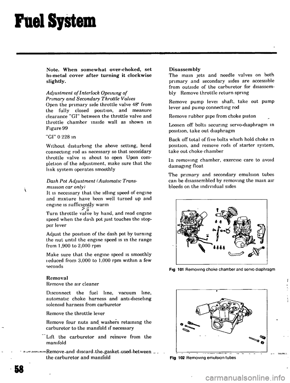
UII
ij
Fig
101
Removmg
choke
chamber
and
servo
diaphragm
o
llQt
o
Fig
102
Removmg
emulsion
tubes
Page 69 of 136
Brakes
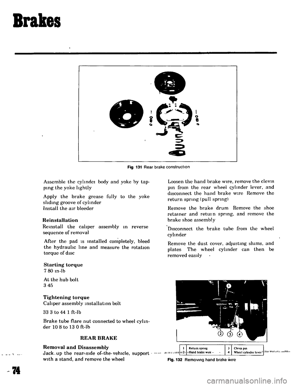
c
Fig
131
Rear
brake
construction
Assemble
the
cylIndel
body
and
yoke
by
tap
ping
the
yoke
lIghtly
Apply
the
brake
grease
fully
to
the
yoke
slIding
groove
of
cylInder
I
nstall
the
air
bleeder
Reinstallation
Reinstall
the
calIper
assembly
In
reverse
sequence
of
removal
After
the
pad
IS
Installed
completely
bleed
the
hydraulIc
line
and
measure
the
rotatton
torque
of
diSC
Starting
torque
780
In
Ib
At
the
hub
bolt
345
Tightening
torque
CalIper
assembly
installatIOn
bolt
33
3
to
44
1
ft
lb
Brake
tube
flare
nut
connected
to
wheel
cylIn
der
108
to
13
0
ft
lb
REAR
BRAKE
Removal
and
Disassembly
Jack
up
the
rear
slde
of
the
vehicle
support
With
a
stand
and
remove
the
wheel
74
Loosen
the
hand
brake
Wire
remove
the
cleVIS
pin
from
the
rear
wheel
l
ylInder
lever
and
disconnect
the
hand
brake
wIre
Remove
the
return
spnng
pull
spnng
Remove
the
brake
drum
Remove
the
shoe
retainer
and
retUl
n
spnng
and
remove
the
brake
shoe
assembly
DIsconnect
the
brake
tube
from
the
wheel
cylinder
Remove
the
dust
cover
adjusting
shims
and
plates
The
wheel
cylInder
can
then
be
removed
eaSily
Flg
132
RemOVing
hand
brake
vme
Page 73 of 136
Brakes
ADJUSTMENT
Front
Disc
Brake
Ordinarily
adJu
tment
IS
not
requIred
because
clearance
between
pad
and
rotor
IS
adjusted
automattcally
by
elasttclty
of
the
pIston
seal
I
iJ
1
el
i
C
1
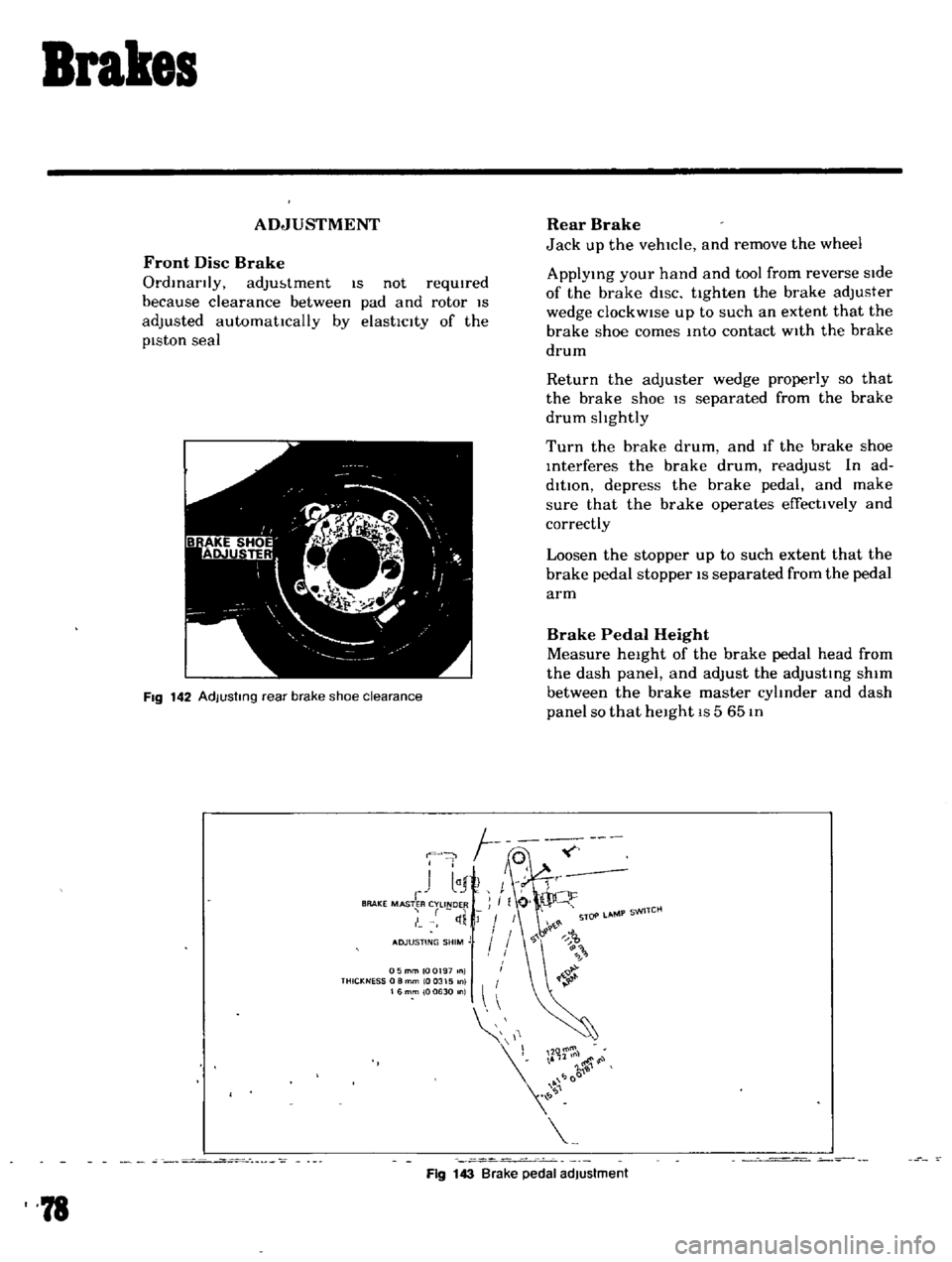
FIg
142
AdJustmg
rear
brake
shoe
clearance
F
J
I
1
I
r
BRAKE
MASTER
CYLINDER
I
tI
Rear
Brake
Jack
up
the
vehicle
and
remove
the
wheel
ApplYing
your
hand
and
tool
from
reverse
side
of
the
brake
diSC
ttghten
the
brake
adjuster
wedge
clockWise
up
to
such
an
extent
that
the
brake
shoe
comes
Into
contact
With
the
brake
drum
Return
the
adjuster
wedge
properly
so
that
the
brake
shoe
IS
separated
from
the
brake
drum
slIghtly
Turn
the
brake
drum
and
If
the
brake
shoe
Interferes
the
brake
drum
readjust
In
ad
dition
depress
the
brake
pedal
and
make
sure
that
the
brake
operates
effecttvely
and
correctly
Loosen
the
stopper
up
to
such
extent
that
the
brake
pedal
stopper
IS
separated
from
the
pedal
arm
Brake
Pedal
Height
Measure
height
of
the
brake
pedal
head
from
the
dash
panel
and
adjust
the
adjusting
shim
between
the
brake
master
cylInder
and
dash
panel
so
that
height
IS
5
65
In
05mmlOQ197
nl
THICKNESS
0
8
mm
10
0315
0
16mm
100630
n
11
r
l00
Fig
143
Brake
pedal
adjustment
78
Page 81 of 136
i
l
Front
SuspeDsion
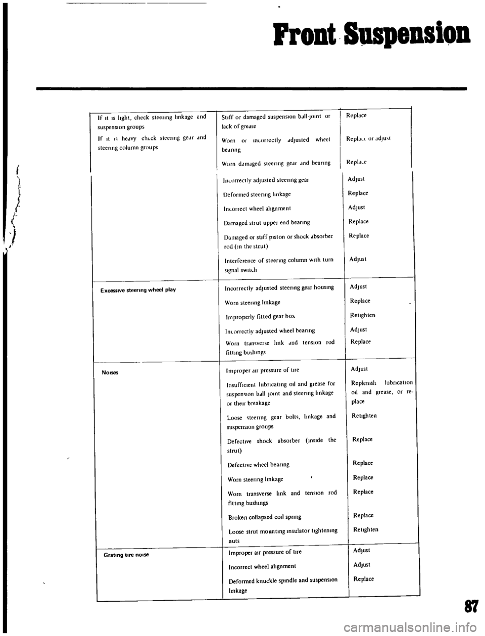
If
t
IS
lIght
check
stecrmg
hnkage
and
suspension
groups
If
It
I
hectvy
chl
ck
sleermg
geM
wd
stcermg
column
groups
Excessive
steering
wheel
play
1
NOises
Grating
tire
nOise
StIff
or
dJmaged
5llspenslUn
bJII
Jomt
or
lack
of
gTcelse
Worn
01
lIKorrcctly
ddJuSICd
whed
bCJfIll
g
Worn
dJtnJged
steering
gedf
Jod
bearmg
In
orrectly
adjusted
teenng
gear
Deformed
steering
Imkage
In
orrcct
wheel
alignment
Damaged
strut
upper
end
bearmg
Damaged
or
stiff
piston
or
shock
dbsorber
rod
m
the
strut
Interference
of
steenng
column
Wllh
turn
signal
sWlh
h
Incorrectly
adjusted
steenng
gear
housmg
Worn
steenng
lmkage
Improperly
fitted
gear
box
1n
orrectJy
adjusted
wheel
bearIng
Worn
trdl1Wcrs
e
hnk
dnd
tensIOn
rod
f1ttlllg
bmhlOgs
Improper
lIT
pressure
of
lire
InsuffiCient
lubncatmg
011
and
grease
for
suspen
lOn
b
t11
Jomt
and
steermg
hnkage
or
then
breakage
Loose
teermg
gear
bolt
Imkage
and
suspension
groups
Defective
shock
absorber
mslde
the
slrut
Defective
wheel
bearmg
Worn
sleenng
Imkage
Worn
transverse
hnk
and
tenston
rod
fiUmg
bushmgs
Broken
collapsed
rod
sprmg
Loose
strut
mountmg
Insulator
tJghtemng
nuts
Improper
aJf
pressure
of
tlfe
Incorrect
wheel
alIgnment
Deformed
knuckle
spmdle
and
suspensIOn
linkage
RcplJce
ReplJLL
or
JdJu
t
ReplJLc
AdJusl
Replace
Adlust
Replace
Replace
Adlusl
Adjust
Replace
Retighten
Adjust
Replace
Adlusl
Replemsh
lubncatlOn
od
and
grease
or
re
place
Retighten
Replace
Replace
Replace
Replace
Replace
Retighten
Adjust
Adjust
Replace
81
Page 84 of 136
Steering
DESCRIPTION
mtles
and
replenIsh
recommended
011
as
reqUIred
The
steetlng
linkage
should
be
greased
up
WIth
wheel
bearing
grease
every
30
000
mtles
The
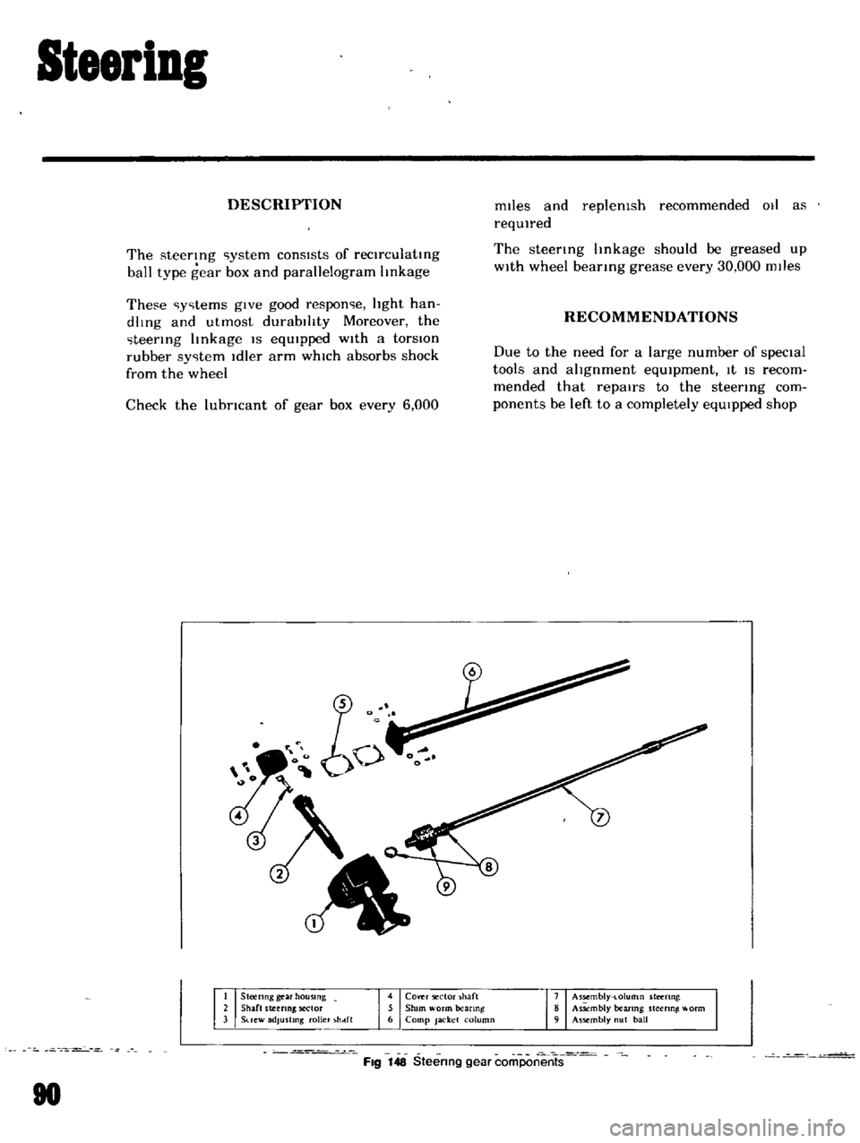
steering
ystem
consIsts
of
reclrculatmg
ball
type
gear
box
and
parallelogram
linkage
These
y
tems
gIve
good
respon
e
light
han
dlmg
and
utmost
durabIlity
Moreover
the
teermg
linkage
IS
eqUIpped
With
a
torsIOn
rubber
sy
tem
Idler
arm
whIch
absorbs
shock
from
the
wheel
RECOMMENDATIONS
Check
the
lubricant
of
gear
box
every
6
000
Due
to
the
need
for
a
large
number
of
specIal
tools
and
alignment
eqUIpment
It
IS
recom
mended
that
repairs
to
the
steering
com
ponents
be
left
to
a
completely
eqUIpped
shop
Steenng
gear
housing
Shaft
steeling
sector
Suew
adjusting
roller
hdft
4
Cover
ector
haft
5
Shim
worm
anng
6
Camp
Jacket
column
7
Assembly
t
olumn
steering
8
As
mbly
bearmg
steering
l
orm
9
Assembly
ut
ball
Fig
148
Steering
gear
coriiPon
rrts
80
Page 87 of 136
lear
Drive
Suspension
I
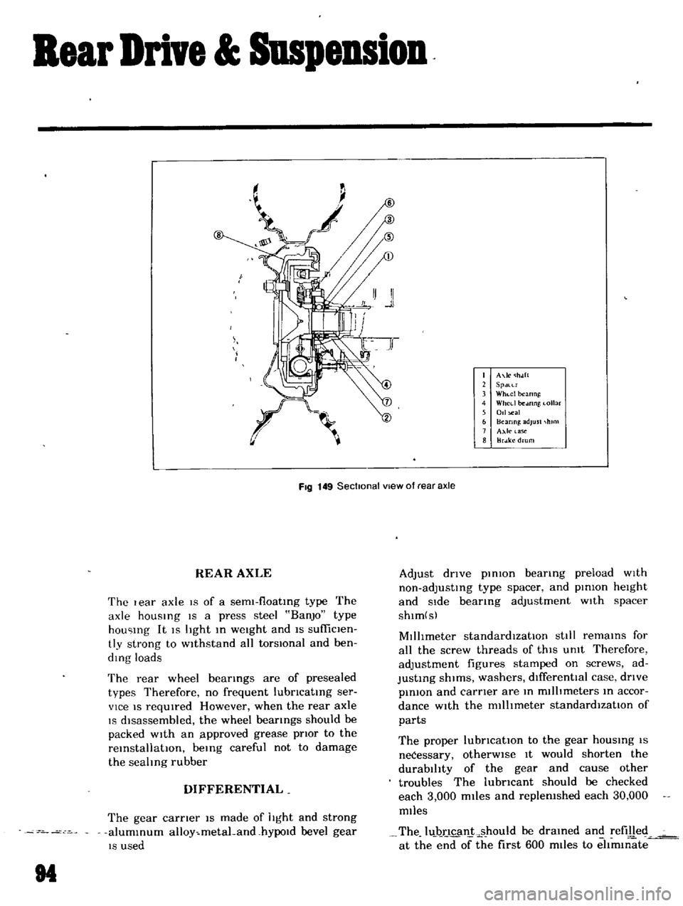
A
le
holft
2
SPdlU
3
Whl
c1
beanng
4
Whcd
be
mng
I
ollar
5
Oll
al
b
Hcanng
adjust
hlOl
7
Axle
a
C
8
BrJ
ke
drum
FIg
149
Sectional
vIew
of
rear
axle
REAR
AXLE
The
I
ear
axle
19
of
a
sem1
f10atIng
type
The
axle
hOUSIng
IS
a
press
steel
BanjO
type
hou
Ing
It
IS
light
In
weight
and
IS
sufficlen
tly
strong
to
wIthstand
all
torsIOnal
and
ben
ding
loads
The
rear
wheel
bearIngs
are
of
presealed
types
Therefore
no
frequent
lubncatIng
ser
vice
IS
reqUIred
However
when
the
rear
axle
IS
dIsassembled
the
wheel
bearings
should
be
packed
with
an
lpproved
grease
pnor
to
the
reInstallatIOn
beIng
careful
not
to
damage
the
sealing
rubber
DIFFERENTIAL
The
gear
carner
IS
made
of
light
and
strong
alumInum
alloy
metaLand
hYPOld
bevel
gear
IS
used
M
Adjust
dnve
pInIOn
bearIng
preload
wIth
non
adjustIng
type
spacer
and
pInion
height
and
Side
bearIng
adjustment
wIth
spacer
shlm
s
MIllimeter
standardIzatIOn
stili
remaInS
for
all
the
screw
threads
of
thIS
Unit
Therefore
adjustment
figures
stamped
on
screws
ad
JustIng
shIms
washers
dIfferentIal
case
dnve
pInIOn
and
carner
are
In
millimeters
In
accor
dance
with
the
millImeter
standardIzatIOn
of
parts
The
proper
lubncatlOn
to
the
gear
hOUSIng
IS
neCessary
otherWIse
It
would
shorten
the
durability
of
the
gear
and
cause
other
troubles
The
lubncant
should
be
checked
each
3
000
miles
and
replenished
each
30
000
miles
The
luJ
ncan
ks
hould
be
draIned
and
refilled
at
the
end
of
the
first
600
miles
to
eltm1l1ate
Page 91 of 136
Clutch
DESCRIPTION
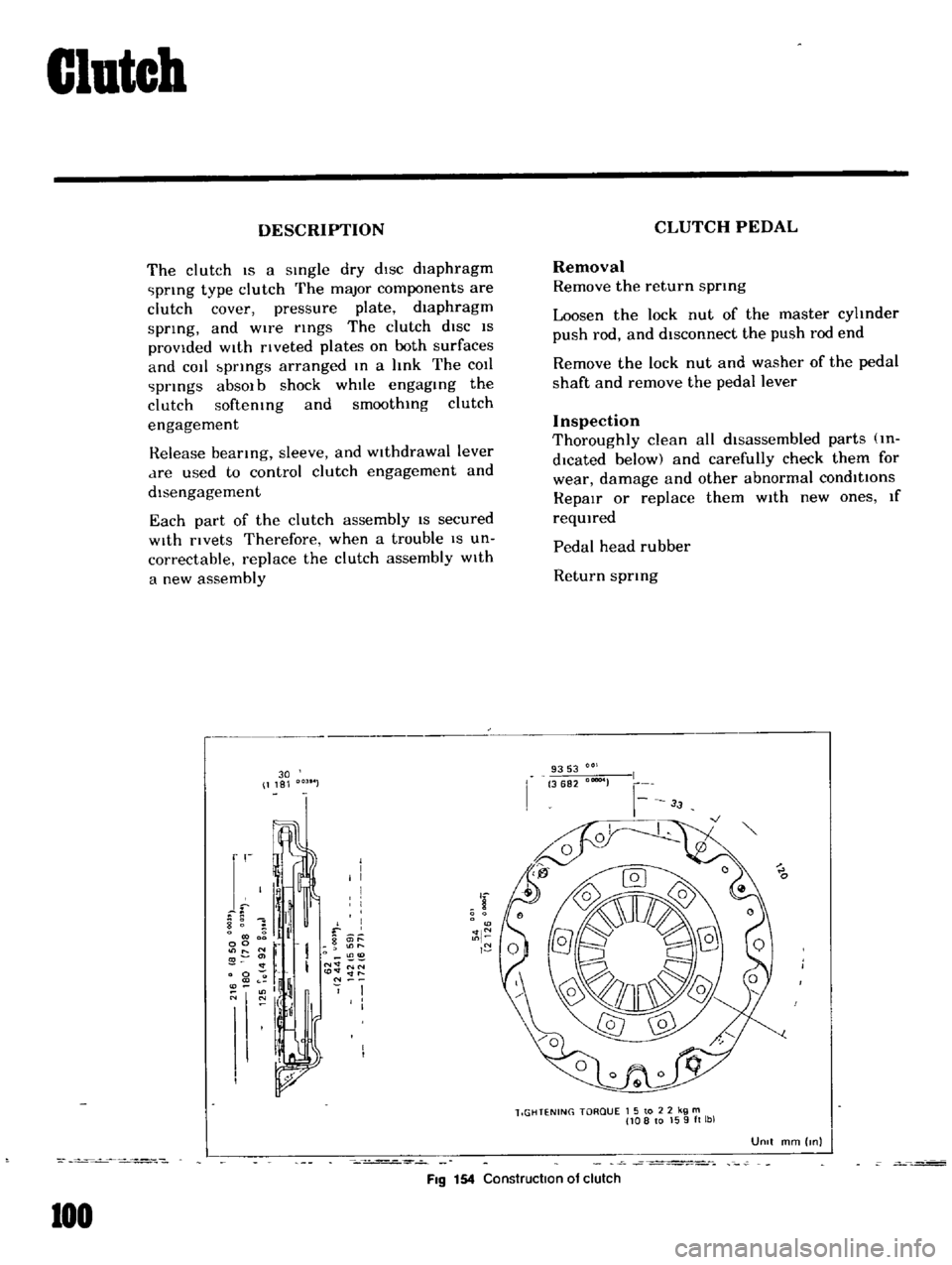
The
clutch
IS
a
sIngle
dry
dIsc
diaphragm
prIng
type
clutch
The
major
components
are
clutch
cover
pressure
plate
diaphragm
sprIng
and
wire
rIngs
The
clutch
diSC
IS
provided
WIth
rIveted
plates
on
both
surfaces
and
cot
bprIngs
arranged
In
a
hnk
The
COIl
prIngs
absOl
b
shock
whIle
engagIng
the
clutch
softemng
and
smoothIng
clutch
engagement
Release
bearIng
sleeve
and
WIthdrawal
lever
dre
used
to
control
clutch
engagement
and
disengagement
Each
part
of
the
clutch
assembly
IS
secured
With
rivets
Therefore
when
a
trouble
IS
un
correctable
replace
the
clutch
assembly
With
a
new
assembly
30
1181
r
I
I
I
I
I
8
1
il
f
0
g
it
l
00
r
O
11
I
N
NN
0
to
lt
lt
ll
l
If
N
O
N
I
I
I
I
FIg
154
Construction
of
clutch
100
CLUTCH
PEDAL
Removal
Remove
the
return
sprmg
Loosen
the
lock
nut
of
the
master
cyhnder
push
rod
and
disconnect
the
push
rod
end
Remove
the
lock
nut
and
washer
of
the
pedal
shaft
and
remove
the
pedal
lever
Inspection
Thoroughly
clean
all
disassembled
parts
m
dlcated
below
and
carefully
check
them
for
wear
damage
and
other
abnormal
conditions
RepaIr
or
replace
them
With
new
ones
If
reqUIred
Pedal
head
rubber
Return
sprIng
9353
3682
00004
lIGHTENING
TORQUE
1
5
to
2
2
kg
m
108
to
159ft
lbl
UOIt
mm
Inl