1969 DATSUN B110 differential
[x] Cancel search: differentialPage 5 of 136
labl8
of
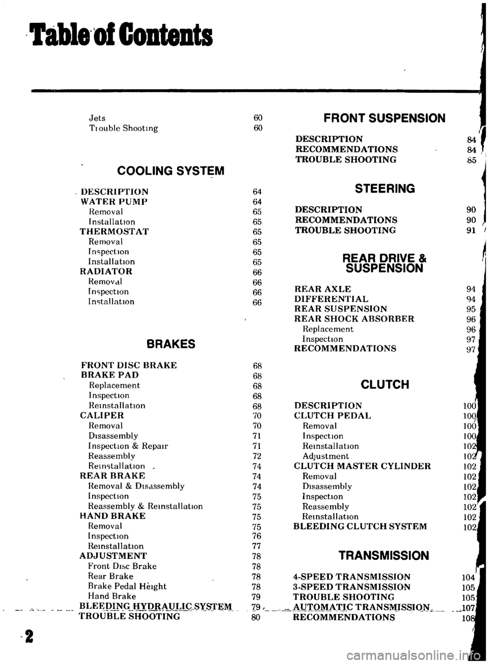
Contents
Jets
60
FRONT
SUSPENSION
TlOuble
Shooting
60
f
DESCRIPTION
RECOMMENDATIONS
TROUBLE
SHOOTING
I
85
COOLING
SYSTEM
DESCRIPTION
64
STEERING
WATER
PUMP
64
Hemoval
65
DESCRIPTION
90
InstallatIOn
65
RECOMMENDATIONS
90
THERMOSTAT
65
TROUBLE
SHOOTING
91
Removal
65
InspectIOn
65
REAR
DRIVE
Installation
65
RADIATOR
66
SUSPENSION
Hemovdl
66
InspectIOn
66
REAR
AXLE
94
InstallatIOn
66
DIFFERENTIAL
94
REAR
SUSPENSION
95
REAR
SHOCK
ABSORBER
96
Replacement
96
BRAKES
InspectIOn
97
RECOMMENDATIONS
97
FRONT
DISC
BRAKE
68
BRAKE
PAD
68
Replacement
68
CLUTCH
InspectIOn
68
ReinstallatIOn
68
DESCRIPTION
CALIPER
70
CLUTCH
PEDAL
Removal
70
Removal
Disassembly
71
InspectIOn
InspectIOn
Repmr
71
ReinstallatIOn
Reassembly
72
Adjustment
ReinstallatIOn
74
CLUTCH
MASTER
CYLINDER
REAR
BRAKE
74
Removal
Hemoval
Dlsdssembly
74
DIsassembly
InspectIOn
75
InspectIOn
Reassembly
ReinstallatIOn
75
Reassembly
HAND
BRAKE
75
RemstallatlOn
Removal
75
BLEEDING
CLUTCH
SYSTEM
InspectIOn
76
RemstallatlOn
77
ADJUSTMENT
78
TRANSMISSION
Front
DI
c
Brake
78
Rear
Brake
78
4
SPEED
TRANSMISSION
Brake
Pedal
HeIght
78
3
SPEED
TRANSMISSION
Hand
Brake
79
TROUBLE
SHOOTING
BLEEPIN
HYD
AULIC
SYs
r
M
79
i
UIQM
ATJ
C
TRANSMJSSIQ
TROUBLE
SHOOTING
80
RECOMMENDATIONS
2
Page 15 of 136
Bngine
WIres
for
accelerator
and
choke
The
operatIOn
Will
be
carned
out
more
easily
by
removing
the
a1r
cleaner
Lift
up
the
engine
toward
the
front
INST
ALLA
TION
Install
the
engine
In
reverse
sequence
of
removal
Disconnecting
clutch
wire
on
nght
hand
dnve
model
On
left
hand
dnve
model
disconnect
hydraulIc
line
from
the
clutch
slave
cylInder
DIsconnect
the
clutch
WIre
at
the
JXlrtlOn
of
the
wIthdrawal
lever
Remove
the
exhaust
front
tube
Disconnect
the
the
cable
to
the
back
up
lamp
SWItch
D1sconnect
the
speedometer
cable
Remove
the
propeller
shaft
Remove
four
bolts
used
In
the
differential
carner
SIde
and
Withdraw
the
propeller
shaft
Remove
the
shift
lever
Model
With
remote
control
shIft
lever
Disconnect
the
remote
control
rod
at
the
JXlr
tlOn
of
transmiSSIOn
outer
lever
and
remove
the
remote
control
rod
Model
With
floor
Sh1ft
lever
Remove
the
boot
WIthdraw
the
lock
pin
and
remove
the
lever
The
operatIOn
IS
carned
out
In
the
passenger
compartment
Model
With
automatic
transmiSSIOn
Remove
pinS
from
both
ends
of
the
cross
shaft
and
remove
the
shIft
rod
Suspend
the
engine
With
wire
Remove
the
front
engine
mounting
installation
nuts
Remove
the
rear
engine
mounting
installation
nuts
When
removing
the
engine
mounting
in
stallation
nuts
be
sure
to
apply
a
Jack
beneath
the
transmiSSIOn
CLEANING
AND
INSPECTION
Clean
the
engine
thoroughly
before
disassem
bly
Before
cleaning
the
engine
remove
the
l
electncal
parts
and
plug
up
the
carburetor
air
horn
to
aVOid
intrusIOn
of
foreign
matter
The
engine
extenor
Check
the
covers
and
bolts
for
breakage
rust
damage
and
loss
CylInder
block
Check
thoroughly
the
water
Jacket
for
cracks
and
breakage
Clutch
hOUSing
Check
for
cracks
011
pan
Check
for
excessive
rust
DISASSEMBLY
Mount
engine
assembly
on
engine
stand
Remove
the
engine
mounting
bracket
R
H
Side
Install
the
engine
attachment
Mount
the
engine
on
the
stand
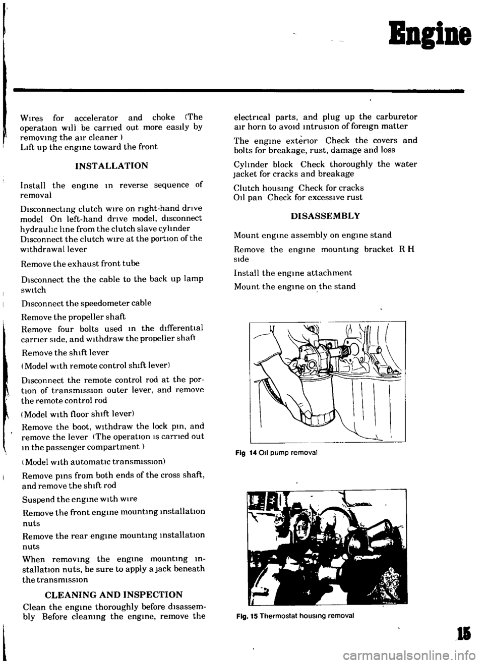
Fig
14011
pump
removal
Fig
15
Thermostat
hOUSing
removal
II
Page 87 of 136
lear
Drive
Suspension
I
A
le
holft
2
SPdlU
3
Whl
c1
beanng
4
Whcd
be
mng
I
ollar
5
Oll
al
b
Hcanng
adjust
hlOl
7
Axle
a
C
8
BrJ
ke
drum
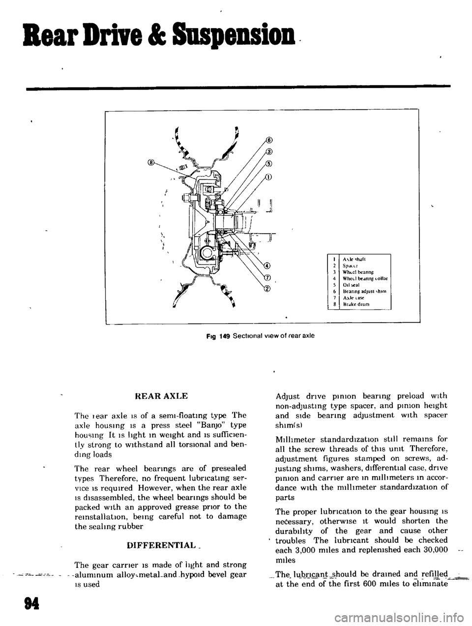
FIg
149
Sectional
vIew
of
rear
axle
REAR
AXLE
The
I
ear
axle
19
of
a
sem1
f10atIng
type
The
axle
hOUSIng
IS
a
press
steel
BanjO
type
hou
Ing
It
IS
light
In
weight
and
IS
sufficlen
tly
strong
to
wIthstand
all
torsIOnal
and
ben
ding
loads
The
rear
wheel
bearIngs
are
of
presealed
types
Therefore
no
frequent
lubncatIng
ser
vice
IS
reqUIred
However
when
the
rear
axle
IS
dIsassembled
the
wheel
bearings
should
be
packed
with
an
lpproved
grease
pnor
to
the
reInstallatIOn
beIng
careful
not
to
damage
the
sealing
rubber
DIFFERENTIAL
The
gear
carner
IS
made
of
light
and
strong
alumInum
alloy
metaLand
hYPOld
bevel
gear
IS
used
M
Adjust
dnve
pInIOn
bearIng
preload
wIth
non
adjustIng
type
spacer
and
pInion
height
and
Side
bearIng
adjustment
wIth
spacer
shlm
s
MIllimeter
standardIzatIOn
stili
remaInS
for
all
the
screw
threads
of
thIS
Unit
Therefore
adjustment
figures
stamped
on
screws
ad
JustIng
shIms
washers
dIfferentIal
case
dnve
pInIOn
and
carner
are
In
millimeters
In
accor
dance
with
the
millImeter
standardIzatIOn
of
parts
The
proper
lubncatlOn
to
the
gear
hOUSIng
IS
neCessary
otherWIse
It
would
shorten
the
durability
of
the
gear
and
cause
other
troubles
The
lubncant
should
be
checked
each
3
000
miles
and
replenished
each
30
000
miles
The
luJ
ncan
ks
hould
be
draIned
and
refilled
at
the
end
of
the
first
600
miles
to
eltm1l1ate
Page 88 of 136
Bear
Drive
Suspension
A
correct
contact
pattern
means
that
It
beii
the
ange
of
2
3
to
3
4
from
the
tip
of
the
tooth
nder
no
load
Backlash
IS
010
to
015mm
00039
to
00059
n
Tlghtemng
torque
of
drlve
gear
bolt
60
to
70
kg
m
434
to
506
ft
Ibl
TIghten
by
tapping
bolt
head
with
a
0
lkg
1
4
lb
hammer
TIghtening
torque
of
dnvt
pmlon
nut
12
to
11
kg
m
86
8
to
1229
ft
lb
Plmon
be
nng
adjust
spacer
O
lve
plmon
adlustlng
washer
T
W
N
HxO
011
0
2
mml
T
T
Drive
gear
ad
ustlng
shims
Left
Ide
T1
jA
C
0
H
I
001
0200
E
lmml
Right
SIde
T2
B
D
HI
001
0
200
F
mml
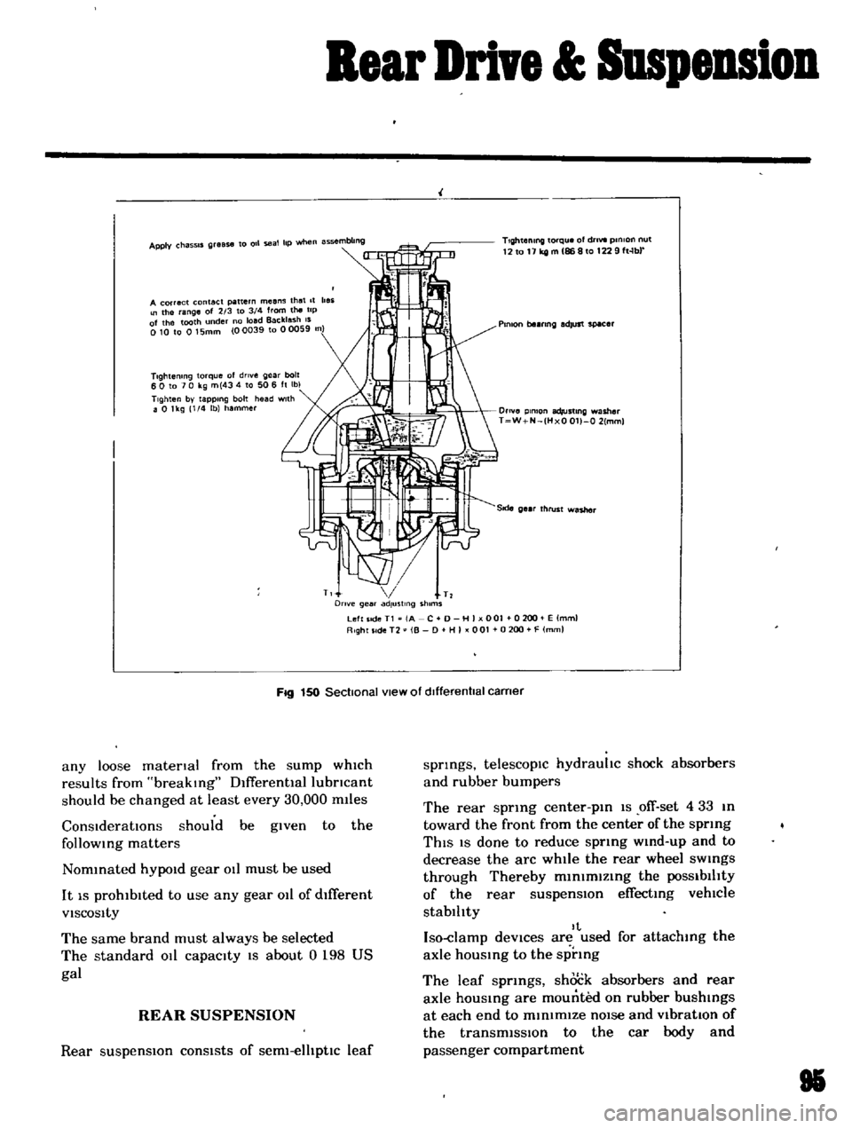
Fig
150
Sectional
view
of
dIfferentIal
carner
any
loose
matenal
from
the
sump
which
results
from
breaking
Dlfferentlallubncant
should
be
changed
at
least
every
30
000
m11es
ConsIderatIOns
should
be
given
to
the
follOWing
matters
Nommated
hYPOld
gear
011
must
be
used
It
IS
prohibited
to
use
any
gear
011
of
dIfferent
VISCOSity
The
same
brand
must
always
be
selected
The
standard
011
capacity
IS
about
0
198
US
gal
REAR
SUSPENSION
Rear
suspensIOn
consists
of
serm
elhptlc
leaf
springs
telescopIc
hydrauhc
shock
absorbers
and
rubber
bumpers
The
rear
sprmg
center
pm
1S
ofT
set
4
33
m
toward
the
front
from
the
center
of
the
sprmg
ThIS
IS
done
to
reduce
sprmg
wmd
up
and
to
decrease
the
arc
while
the
rear
wheel
sWings
through
Thereby
m1n1mlzmg
the
POSSibilIty
of
the
rear
suspensIOn
effecting
vehlCle
stablhty
It
Iso
damp
deVices
are
used
for
attachmg
the
axle
hOUSing
to
the
sprmg
The
leaf
sprmgs
shock
absorbers
and
rear
axle
housmg
are
mounted
on
rubber
bushings
at
each
end
to
minimIZe
nOIse
and
VibratIOn
of
the
transmiSSIon
to
the
car
body
and
passenger
compartment
85
Page 90 of 136
Bear
Drive
Suspension
Install
rear
shock
absorber
m
reverse
equence
of
removal
cracks
and
exceSSIve
deformatIOn
Replace
the
defectIve
parts
If
necessary
Inspection
Test
the
shock
absorber
and
replace
If
necessary
Check
for
leakage
cracks
and
the
shaft
for
straightness
Inspect
the
rubber
bushmgs
for
damage
RECOMMENDATIONS
Due
to
the
large
number
of
specIal
tools
reqUIred
and
the
advanced
knowledge
necessary
It
IS
recommended
that
the
overhaul
of
the
differential
be
left
to
a
properlv
equipped
shop
97