1969 DATSUN B110 wheel
[x] Cancel search: wheelPage 4 of 136

able
of
Contents
MAINTENANCE
TUNE
UP
DIsassembly
32
InspectIOn
RepaIr
33
VALVE
CLEARANCES
6
AdJustmg
Regulator
33
ENGINE
OIL
6
Assembly
33
OIL
FILTER
7
COOLANT
7
COMPRESSION
7
ELECTRICAL
SYSTEM
BATTERY
8
IGNITION
TIMING
8
STARTER
36
DIstributor
Breaker
Pomt
9
Removal
37
Condenser
9
InstallatIOn
37
Spark
Plugs
9
Trouble
Shootmg
37
Carburetor
9
ALTERNATOR
36
Idle
LImIter
Cap
10
Removal
37
Dash
Pot
automatic
transmISSIOn
11
InstallatIOn
37
model
only
11
REGULATOR
39
Carburetor
Return
Sprmg
11
DeSCriptIOn
39
Fuel
Filter
11
Trouble
Shootmg
40
ENGINE
IGNITION
SYSTEM
DESCRIPTION
14
DISTRIBUTOR
44
REMOVAL
14
ConstructIOn
44
INSTALLATION
14
Checkmg
and
Adjustment
44
CLEANING
INSPECTION
14
SP
ARK
PLUGS
46
DISASSEMBL
Y
14
DeSCriptIOn
46
INSPECTION
REPAIR
18
InspectIOn
46
PreparatIOn
18
Cleamng
Regap
47
Cyltnder
Head
18
Valve
Assembly
18
Valve
Spnng
19
Valve
Rocker
Shaft
Rocker
Arm
19
FUEL
SYSTEM
Valve
LIfter
Push
Rod
20
Camshaft
Camshaft
Bearmg
20
FUEL
FILTER
50
Valve
Tlmmg
20
DESCRIPTION
50
Cyltnder
Block
21
REMOVAL
50
PIston
Piston
Pm
Plsto
LRmg
21
INSTALLATION
50
Connectmg
Rod
23
FUEL
PUMP
50
Crankshaft
24
DeSCriptIOn
50
Bushmg
Bearing
24
Testmg
51
Crankshaft
Sprocket
Removal
DIsassembly
52
Camshaft
Sprocket
25
InspectIOn
52
Flywheel
25
Assembly
52
ASSEMBL
Y
25
CARBURETOR
52
PrecautIOn
25
DeSCription
52
Cyltnder
Head
25
Adjustment
53
PIston
ConnectIng
Rod
26
Removal
58
Engme
26
DIsassembly
58
OIL
PUMP
32
Cleanmg
InspectIOn
59
Removal
Engme
m
vehicle
32
Assembly
InstallatIOn
60
I
Page 12 of 136
aiDteDaDce
UDe
up
Adjust
throttle
adjusting
screw
so
that
engme
speed
1S
800
rpm
m
N
positIOn
for
automatic
transmIssIOn
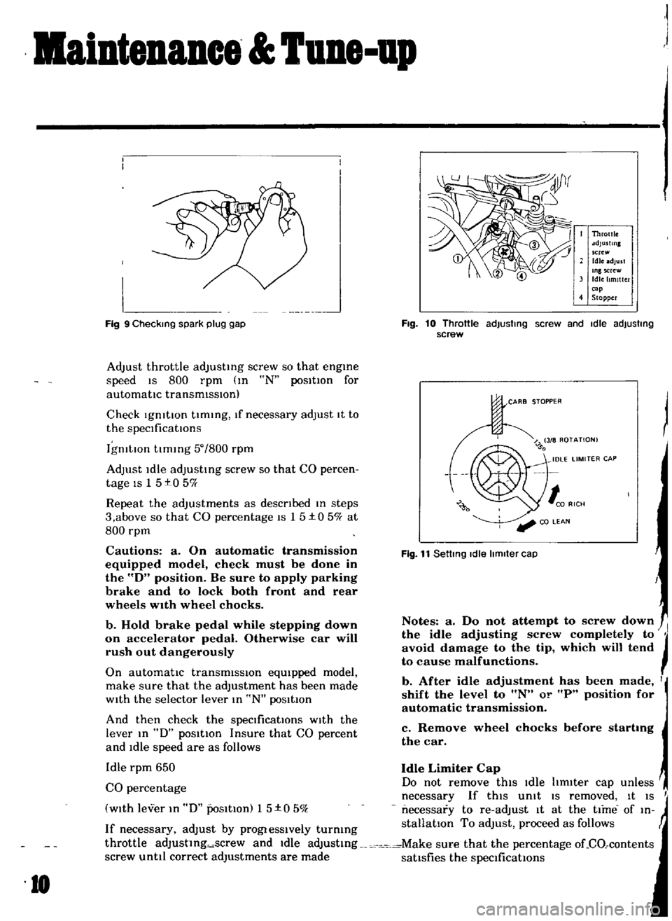
Check
IgnitIOn
tlmmg
If
necessary
adjust
1t
to
the
specIficatIOns
IgnitIOn
timing
50
800
rpm
Adjust
Idle
adjusting
screw
so
that
CO
percen
tage
IS
1
5
t0
5
ff
Repeat
the
adjustments
as
desctlbed
In
steps
3
above
so
that
CO
percentage
IS
15
t0
5
ff
at
800
rpm
Cautions
a
On
automatic
transmission
equipped
model
check
must
be
done
in
the
D
position
Be
sure
to
apply
parking
brake
and
to
lock
both
front
and
rear
wheels
wIth
wheel
chocks
b
Hold
brake
pedal
while
stepping
down
on
accelerator
pedal
Otherwise
car
will
rush
out
dangerously
On
automatic
transmISSIOn
eqUIpped
model
make
sure
that
the
adjustment
has
been
made
wIth
the
selector
lever
In
N
posItion
And
then
check
the
specificatIOns
with
the
lever
In
D
posItion
Insure
that
CO
percent
and
Idle
speed
are
as
follows
Idle
rpm
650
Idle
Limiter
Cap
CO
percentage
Do
not
remove
this
Idle
hm1ter
cap
unless
necessary
If
this
Unit
IS
removed
It
IS
I
with
lever
In
D
PoSitIOn
1
5
t
0
5
k
necessary
to
re
adJust
It
at
the
time
of
In
If
necessary
adjust
by
progIesslvely
turmng
stallatlon
To
adjust
proceed
as
follows
throttle
adJustlng
screw
and
Idle
adJustmg
Make
sure
that
the
percentage
oLCO
contents
screw
until
correct
adjustments
are
made
satisfies
the
specifications
I
I
I
I
J
Fig
9
Checking
spark
plug
gap
10
Throttle
sdJustlnl
screw
Idle
adjust
Inlscrew
Idle
Itmlttc
r
cap
4
Stopper
Fig
10
Throttle
adjusting
screw
and
Idle
adjusting
screw
CARB
STOPPER
Fig
11
Setting
Idle
limiter
cap
Notes
a
Do
not
attempt
to
screw
down
the
idle
adjusting
screw
completely
to
JI
avoid
damage
to
the
tip
which
will
tend
to
cause
malfunctions
b
After
idle
adjustment
has
been
made
I
shift
the
level
to
N
or
P
position
for
automatic
transmission
c
Remove
wheel
chocks
before
startmg
the
car
Page 17 of 136
Bneine
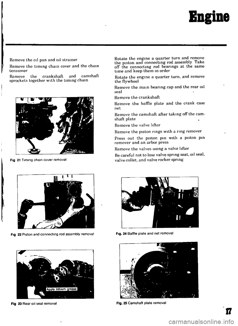
Remove
the
011
pan
and
011
straIner
Remove
the
tImIng
chaIn
cover
and
the
chaIn
tenSlOner
Remove
the
crankshaft
and
camshaft
sprockets
together
WIth
the
timing
chaIn
Fig
21
Tlmmg
cham
cover
removal
I
FIg
22
PIston
and
connectmg
rod
assembly
removal
Fig
23
Rear
011
seal
removal
Rotate
the
engIne
a
quarter
turn
and
remove
the
piston
and
connectIng
rod
assembly
Take
off
the
connectIng
rod
beatings
at
the
same
tIme
and
keep
them
In
order
Rotate
the
engIne
a
quarter
turn
and
remove
the
flywheel
Remove
the
maIn
bearIng
cap
and
the
rear
011
seal
Remove
the
crankshaft
Remove
the
baffie
plate
and
the
crank
case
net
Remove
the
camshaft
after
takIng
off
the
cam
shaft
plate
Remove
the
valve
tfter
Remove
the
piston
rIngs
With
a
tlng
remover
Press
out
the
piston
pIn
With
a
piston
pin
remover
and
an
arbor
press
Remove
the
valves
USIng
a
valve
tfter
Be
careful
not
to
lose
valve
sprIng
seat
011
seal
valve
collet
and
valve
rocker
sprIng
FIg
24
Baffle
plate
and
net
removal
Fig
25
Camshaft
plate
removal
17
Page 25 of 136
Ingine
1
Cut
a
plastIgage
to
the
wIdth
of
the
bearing
and
place
It
m
parallel
with
the
crank
pm
gettmg
clear
of
the
011
hole
Install
the
cap
on
the
assembly
and
tighten
them
together
with
the
specified
torque
Tlghtentng
torque
36
to
43
ft
lb
Note
Be
sure
not
to
turn
the
crankshaft
when
the
plastIgage
is
Inserted
Remove
the
cap
and
measure
wIdth
of
the
plastlgage
at
Its
widest
part
wIth
the
scale
printed
tn
the
plastIgage
envelope
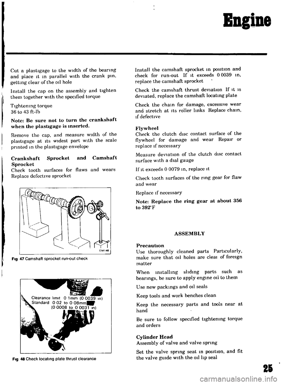
Crankshaft
Sprocket
and
Camshaft
Sprocket
Check
tooth
surfaces
for
flaws
and
wears
Replace
defective
sprocket
EM148
Fig
47
Camshaft
sprocket
run
out
check
Clearance
limit
0
1
mm
00039
m
1
Standard
0
02
to
0
08mm
0
0008
to
0
0031
m
t
Fig
48
Check
locatmg
plate
thrust
clearance
Install
the
camshaft
sprocket
m
posItion
and
check
for
run
out
If
It
exceeds
00039
tn
replace
the
camshaft
sprocket
Check
the
camshaft
thrust
deViatIOn
If
It
IS
deViated
replace
the
camshaft
locatmg
plate
Check
the
cham
for
damage
excessive
wear
and
stretch
at
ItS
roller
Imks
Replace
cham
If
defective
Flywheel
Check
the
clutch
diSC
contact
surface
of
the
flywheel
for
damage
and
wear
Repair
or
replace
If
necessary
Measure
deVtat10n
of
the
clutch
dISC
contact
surface
with
a
dial
gauge
If
It
exceeds
0
0079
m
replace
1t
Check
tooth
surfaces
of
the
ring
gear
for
flaw
and
wear
Replace
If
necessary
Note
Replace
the
ring
gear
at
about
356
to
392
F
ASSEMBLY
PrecautIOn
Use
thoroughly
cleaned
parts
PartIcularly
make
sure
that
011
holes
are
cleal
of
foreign
matter
When
mstalltng
sltdmg
parts
such
as
bearings
be
sure
to
apply
engme
011
to
them
Use
new
packmgs
and
011
seals
Keep
tools
and
work
benches
clean
Keep
the
necessary
parts
and
tools
near
at
hand
Be
sure
to
follow
specified
tIghtemng
torque
and
orders
Cylinder
Head
Assembly
of
valve
and
valve
sprmg
Set
the
valve
sprmg
seat
m
poSItIon
and
fit
the
valve
gUIde
with
the
011
hp
seal
21
Page 27 of 136
Bogine
Note
Set
the
locate
plate
so
as
the
LOWER
mark
comes
to
the
engine
bot
tom
side
Set
the
maIn
bearIngR
on
theIr
posItIOns
on
the
cylinder
block
Notes
a
The
center
bearmg
No
3
bearmg
is
a
flanged
type
for
thrust
force
b
Two
lOner
bearmgs
No
2
and
No
4
are
of
the
same
type
c
The
front
bearmg
No
1
IS
the
same
type
as
the
rear
bearmg
No
5
d
All
bearings
except
for
No
I
bearing
are
interchangeable
between
upper
and
lower
bearings
Apply
engIne
OIl
to
the
mam
bearIng
surfaces
on
both
sIdes
of
the
cyltnder
block
and
cap
Fig
53
Mam
bearing
caps
Fig
54
Crankshaft
end
play
check
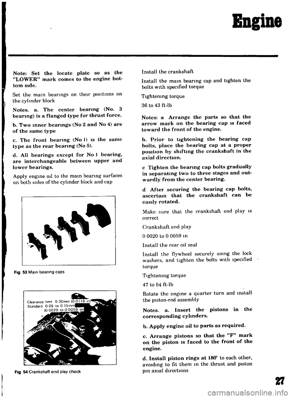
Install
the
crankshaft
Install
the
mam
bearmg
cap
and
tighten
the
bolts
with
specified
torque
Tlghtemng
torque
36
to
43
ft
Ib
Notes
a
Arrange
the
parts
so
that
the
arrow
mark
on
the
bearing
cap
IS
faced
toward
the
front
of
the
engine
b
Prior
to
tightening
the
bearing
cap
bolts
place
the
bearing
cap
at
a
proper
posItIon
by
shlftmg
the
crankshaft
in
the
axial
direction
c
Tighten
the
bearmg
cap
bolts
gradually
in
separatmg
two
to
three
stages
and
out
wardly
from
the
center
bearing
d
After
securing
the
bearing
cap
bolts
ascertam
that
the
crankshaft
can
be
easily
rotated
Make
sure
that
the
crankshaft
end
play
IS
correct
Crankshaft
end
play
o
0020
to
0
0059
In
I
nstalI
the
rear
011
seal
Install
the
flywheel
securely
USIng
the
lock
washers
and
tighten
the
bolts
with
specIfied
torque
Tlghtemng
torque
47
to
54
ft
Ib
Rotate
the
engine
a
quarter
turn
and
mstall
the
piston
rod
assembly
Notes
a
Insert
the
pistons
in
the
corresponding
cyhnders
b
Apply
engine
oil
to
parts
as
required
c
Arrange
pistons
so
that
the
F
mark
on
the
piston
IS
faced
to
the
front
of
the
engine
d
Install
piston
rings
at
18
Y
to
each
other
avoIdIng
to
fit
them
In
the
thrust
and
pIston
pIn
aXial
directIOns
27
Page 28 of 136
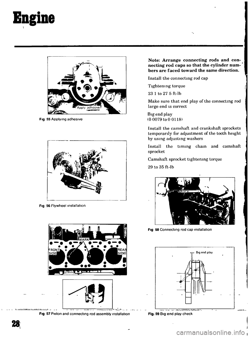
Bagine
Fig
55
ApplYing
adhesive
L
FIg
56
Flywheel
installation
c
0
FIg
57
Piston
and
connecting
rod
assembly
installation
281
Note
Arrange
connecting
rods
and
con
necting
rod
caps
so
that
the
cylinder
num
bers
are
faced
toward
the
same
direction
Install
the
connectmg
rod
cap
Tlghtenmg
torque
23
1
to
27
5
ft
lb
Make
sure
that
end
play
of
the
connectmg
rod
large
end
IS
correct
Big
end
play
00079
to
0
0118
Install
the
camshaft
and
crankshaft
sprockets
temporarily
for
adjustment
of
the
tooth
height
by
usmg
adJustmg
washers
Install
the
tlmmg
cham
and
camshaft
sprocket
Camshaft
sprocket
tlghtemng
torque
29
to
35
ft
lb
FIg
58
Connecting
rod
cap
installation
Fig
59
Big
end
play
check
Page 50 of 136
Fuel
Sptem
The
power
valve
mechanIsm
IS
of
a
vacuum
actuated
boost
type
and
Improves
hIgh
speed
drivIng
The
throttle
opener
control
system
Incor
porates
a
servo
diaphragm
The
servo
dIaphragm
helps
open
the
throttle
valve
at
a
decreasIng
speed
so
as
to
reduce
the
emISSIOn
of
hydrocarbons
to
a
minImum
An
antI
dlesehng
olen01d
IS
used
as
a
means
of
preventIng
dlesehng
When
the
IgnItIOn
key
IS
turned
ofT
the
fuel
passage
Involved
In
the
slow
system
IS
closed
and
the
fuel
supply
IS
shut
down
completely
In
the
chok
mechanIsm
an
electric
automatIc
choke
IS
used
to
automatically
con
trol
the
choke
valve
operatIOn
durIng
the
war
m
up
of
the
engIne
The
carburetor
for
automatic
transmiSSIOn
IS
eqUIpped
WIth
so
called
dash
pot
that
IS
It
makes
smooth
deceleratIng
WIthout
engIne
stall
at
any
operatIng
conditIOn
These
carburetors
are
qUIte
SImIlar
In
ap
pearance
as
explaIned
above
except
the
dash
pot
for
the
automatIc
transmISSion
model
Adjustment
Idhng
Adjustment
Idle
mixture
adjustment
requIres
the
use
of
a
CO
meter
When
prepatlng
to
adjust
Idle
mIxture
It
IS
essentIal
to
have
the
meter
thoroughly
warmed
and
cahbrated
Warm
up
the
engIne
suffiCiently
ContInue
engme
operatIOn
for
one
mmute
un
der
ldhng
speed
Adjust
throttle
adjustIng
screw
so
that
engme
speed
IS
800
rpm
m
N
pos1tIon
for
automatic
transmiSSIOn
Check
IgmtlOn
tl
If
necessary
adjust
It
to
the
speCificatIOns
IgnItIOn
tImlo
800
rpm
Adjust
Idle
adJustmg
screw
so
that
CO
percen
tage
IS
1
5
0
50
at
800
ns
a
On
automatIc
transmiSSIOn
eqUipped
model
check
must
be
done
In
the
D
poSItIon
Be
sure
to
apply
parkmg
brake
and
to
lock
both
front
and
rear
wheels
With
wheel
chocks
b
Hold
brake
pedal
while
steppIng
down
on
accelerator
pedal
OtherWise
car
Will
rush
out
dangerously
On
automatIc
transmiSSIOn
eqUIpped
model
make
sure
that
the
adjustment
has
been
made
With
the
selector
lever
In
N
posItIon
And
then
check
the
specificatIOns
With
the
lever
In
D
pOSitIOn
Insure
that
CO
percent
and
Idle
speed
are
as
follows
Idle
rpm
650
for
Manual
transmISSion
for
Automatic
transmISSion
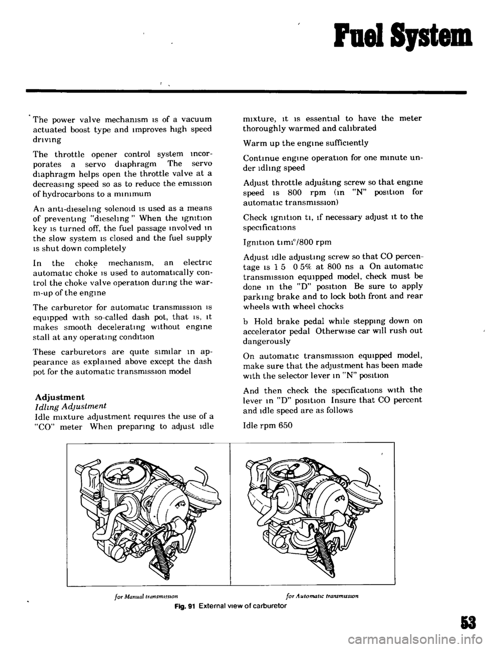
Fig
91
External
view
of
carburetor
3
Page 51 of 136
ruel
Sptem
CO
percentage
with
lever
In
D
posltton
15
050
If
necessary
adjust
by
progressively
turmng
throttle
adjustIng
screw
and
Idle
adJusttng
screw
unttl
correct
adjustments
are
made
Notes
a
Do
not
attempt
to
screw
down
the
Idle
adjusting
screw
completely
to
aVOid
damage
to
the
tip
which
will
tend
to
cause
malfunctions
b
After
idle
adjustment
has
been
made
shift
the
lever
to
UN
or
P
position
for
automatic
transmission
c
Remove
wheel
chocks
before
starting
the
car
Idle
Limiter
Cap
Do
not
remove
this
Idle
hmlter
cap
unless
nccesbary
If
this
Unit
IS
removed
It
IS
I
Throttle
adJu
tmg
suew
2
Idle
adJu
t
Ing
rcw
3
Idle
hmlter
p
4
Stopper
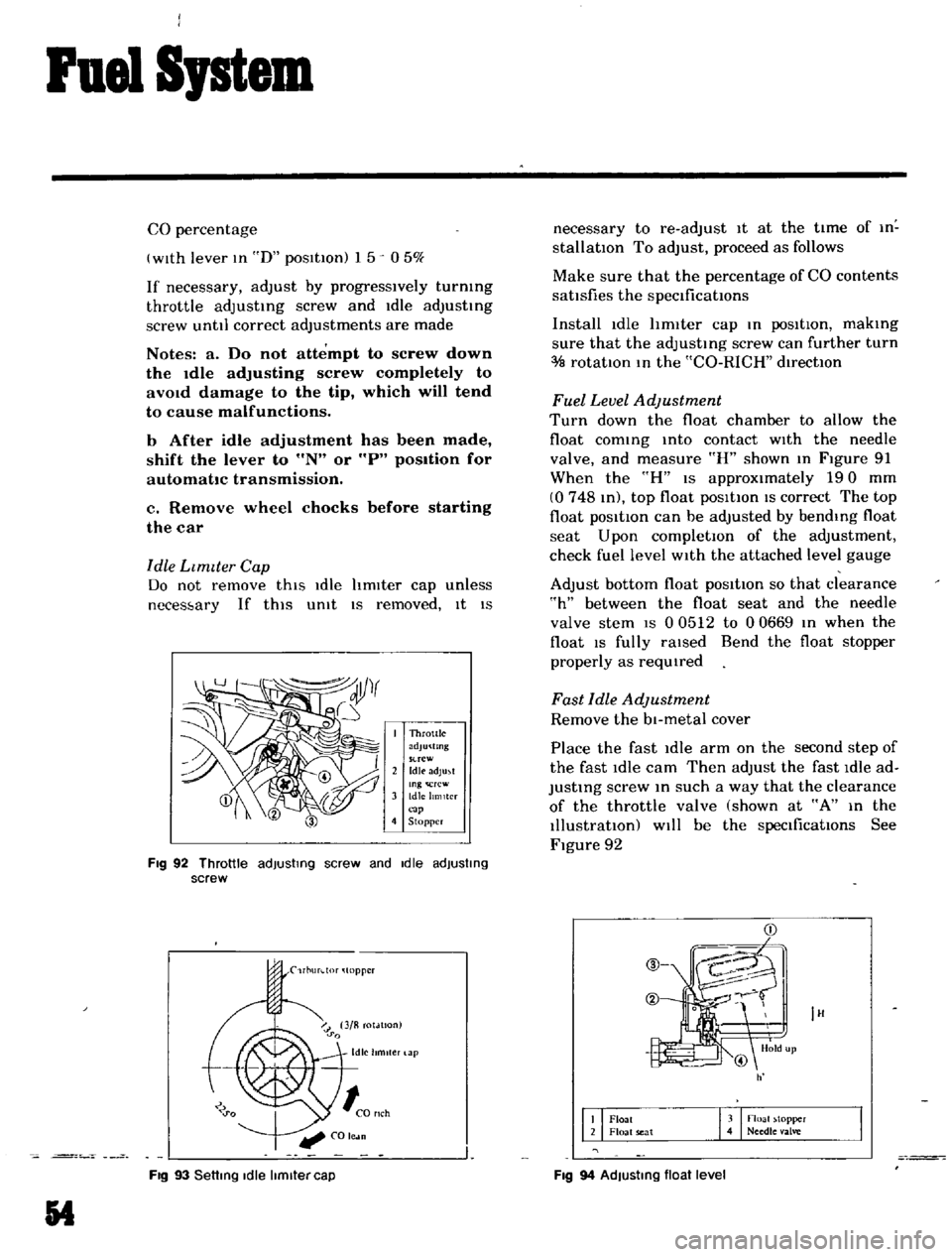
FIg
92
Throttle
adjusting
screw
and
Idle
adjusting
screw
rl1urdor
topper
Fig
93
Setting
Idle
limiter
cap
54
necessary
to
re
adJust
it
at
the
time
of
In
stallatIOn
To
adjust
proceed
as
follows
Make
sure
that
the
percentage
of
CO
contents
sattsfies
the
speClficattons
Install
idle
hmIter
cap
In
poSItIOn
makIng
sure
that
the
adjustIng
screw
can
further
turn
rotatIOn
In
the
CO
RICH
dIrectIOn
Fuel
Level
Adjustment
Turn
down
the
float
chamber
to
allow
the
float
comIng
Into
contact
WIth
the
needle
valve
and
measure
R
shown
In
Figure
91
When
the
H
IS
approximately
190
mm
0748
In
top
float
posltton
IS
correct
The
top
float
pOSitIOn
can
be
adjusted
by
bendIng
float
seat
Upon
completIOn
of
the
adjustment
check
fuel
level
WIth
the
attached
level
gauge
Adjust
bottom
float
posItion
so
that
clearance
h
between
the
float
seat
and
the
needle
valve
stem
IS
0
0512
to
00669
In
when
the
float
IS
fully
raIsed
Bend
the
float
stopper
properly
as
reqUIred
Fast
Idle
Adjustment
Remove
the
bl
metal
cover
Place
the
fast
Idle
arm
on
the
second
step
of
the
fast
idle
cam
Then
adjust
the
fast
Idle
ad
JustIng
screw
In
such
a
way
that
the
clearance
of
the
throttle
valve
shown
at
A
In
the
Illustratton
Will
be
the
speCificatIOns
See
Figure
92
IH
Float
Float
seat
3
noall
topper
4
Needle
alve
Fig
94
AdJusting
float
level