Page 4 of 136

able
of
Contents
MAINTENANCE
TUNE
UP
DIsassembly
32
InspectIOn
RepaIr
33
VALVE
CLEARANCES
6
AdJustmg
Regulator
33
ENGINE
OIL
6
Assembly
33
OIL
FILTER
7
COOLANT
7
COMPRESSION
7
ELECTRICAL
SYSTEM
BATTERY
8
IGNITION
TIMING
8
STARTER
36
DIstributor
Breaker
Pomt
9
Removal
37
Condenser
9
InstallatIOn
37
Spark
Plugs
9
Trouble
Shootmg
37
Carburetor
9
ALTERNATOR
36
Idle
LImIter
Cap
10
Removal
37
Dash
Pot
automatic
transmISSIOn
11
InstallatIOn
37
model
only
11
REGULATOR
39
Carburetor
Return
Sprmg
11
DeSCriptIOn
39
Fuel
Filter
11
Trouble
Shootmg
40
ENGINE
IGNITION
SYSTEM
DESCRIPTION
14
DISTRIBUTOR
44
REMOVAL
14
ConstructIOn
44
INSTALLATION
14
Checkmg
and
Adjustment
44
CLEANING
INSPECTION
14
SP
ARK
PLUGS
46
DISASSEMBL
Y
14
DeSCriptIOn
46
INSPECTION
REPAIR
18
InspectIOn
46
PreparatIOn
18
Cleamng
Regap
47
Cyltnder
Head
18
Valve
Assembly
18
Valve
Spnng
19
Valve
Rocker
Shaft
Rocker
Arm
19
FUEL
SYSTEM
Valve
LIfter
Push
Rod
20
Camshaft
Camshaft
Bearmg
20
FUEL
FILTER
50
Valve
Tlmmg
20
DESCRIPTION
50
Cyltnder
Block
21
REMOVAL
50
PIston
Piston
Pm
Plsto
LRmg
21
INSTALLATION
50
Connectmg
Rod
23
FUEL
PUMP
50
Crankshaft
24
DeSCriptIOn
50
Bushmg
Bearing
24
Testmg
51
Crankshaft
Sprocket
Removal
DIsassembly
52
Camshaft
Sprocket
25
InspectIOn
52
Flywheel
25
Assembly
52
ASSEMBL
Y
25
CARBURETOR
52
PrecautIOn
25
DeSCription
52
Cyltnder
Head
25
Adjustment
53
PIston
ConnectIng
Rod
26
Removal
58
Engme
26
DIsassembly
58
OIL
PUMP
32
Cleanmg
InspectIOn
59
Removal
Engme
m
vehicle
32
Assembly
InstallatIOn
60
I
Page 8 of 136

ainteDaDee
TUDe
up
VAL
VE
CLEARANCES
Valve
clearance
adjustment
should
be
made
while
engme
IS
stationary
To
adjust
proceed
as
follows
Start
engme
and
run
It
until
It
IS
heated
to
operatIng
temperature
or
at
least
more
than
17S
of
engIne
011
temperature
then
stop
engIne
Rotate
crankshaft
to
bnng
No
1
cylInder
In
top
dead
center
on
ItS
compressIOn
stroke
Remove
valve
rocker
cover
to
gaIn
access
to
valve
operatIng
mechamsm
Adjust
valve
clearance
at
follOWing
four
pOints
while
engIne
IS
still
hot
1
Exhaust
valve
of
No
1
cylinder
2
Intake
valve
of
No
1
cylinder
3
Intake
valve
of
No
2
cylinder
5
Exham
t
valve
of
No
3
cylInder
ote
Numbers
in
parenthesis
agree
with
those
10
accompanY1Og
sketch
AgaIn
rotate
crankshaft
one
turn
so
that
No
4
piston
IS
In
top
dead
center
on
ItS
com
pressIOn
stroke
Adjust
follOWIng
valves
4
Exhaust
valve
of
No
2
cylinder
6
Intake
valve
of
No
3
cylinder
7
Intake
valve
of
No
4
cylInder
8
Exhaust
valve
of
No
4
cylinder
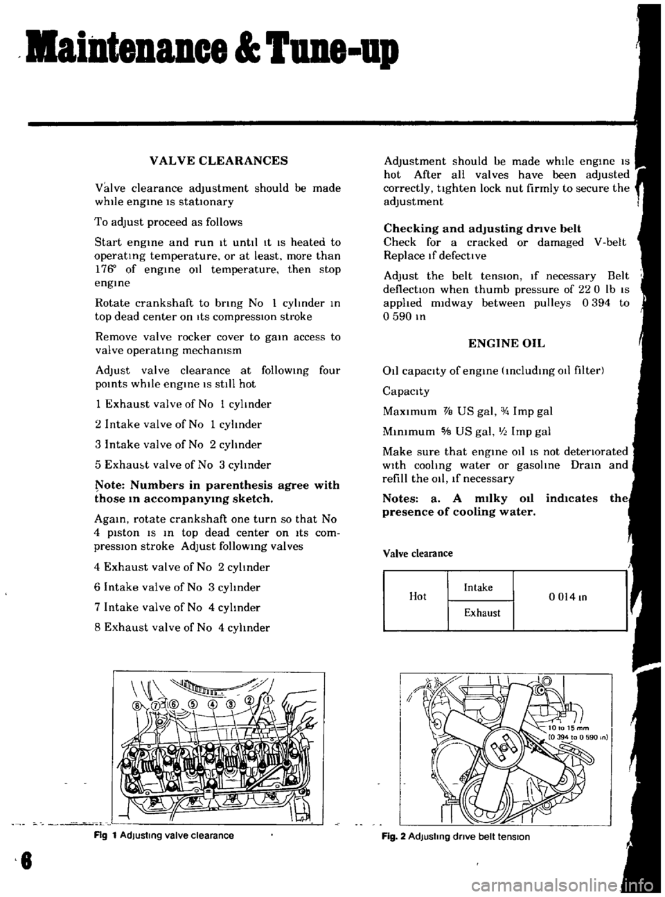
Rg
1
AdJustmg
valve
clearance
8
Adjustment
should
ue
made
whIle
engIne
IS
hot
After
all
valves
have
been
adjusted
correctly
tighten
lock
nut
firmly
to
secure
the
adjustment
Checking
and
adjusting
drive
belt
Check
for
a
cracked
or
damaged
V
belt
Replace
If
defective
Adjust
the
belt
tenSIOn
If
necessary
Belt
deflectIOn
when
thumb
pressure
of
220
Ib
IS
applied
midway
between
pulleys
0394
to
o
590
In
ENGINE
OIL
011
capacity
of
engIne
IncludIng
011
filter
Capacity
MaXimum
VB
US
gal
Imp
gal
MInimum
5IB
US
gal
III
Imp
gal
Make
sure
that
engIne
011
IS
not
detenorated
With
cooling
water
or
gasolIne
DraIn
and
refill
the
011
lf
necessary
Notes
a
A
m1lky
011
indlcates
presence
of
cooling
water
Valve
clearance
Hot
Intake
0014
In
Exhaust
Fig
2
AdJustmg
dnve
belt
tension
Page 9 of 136

aintenIDce
une
up
Find
the
cause
for
necessary
corrective
action
b
Oil
with
extremely
low
viscosity
in
dicates
dllutton
with
gasoline
Check
011
level
If
found
below
L
mark
refill
to
H
mark
on
gauge
OIL
FILTER
The
011
filter
IS
of
a
cartndge
type
Check
for
011
leaks
through
gasketed
flange
If
any
leakage
IS
found
retIghten
shghtly
If
nece
sary
replaLe
filter
as
an
assembly
When
mstalhng
an
011
filter
tIghten
by
hand
Note
Do
not
overtighten
011
fIlter
or
oil
leakage
may
result
I
I
Fig
3
Checking
engine
011
level
Oc
OF
I
0
121
20141
30
21
401401
5015BI
I
EGOQl
I
10
20
Fig
4
Protection
concentration
COOLANT
L
L
C
IS
al
ethylene
glycol
base
product
con
tammg
chemical
mhlbltors
to
protect
the
coohng
system
from
rustmg
and
corrosIOn
The
L
I
C
does
not
con
tam
any
glycerme
ethyl
or
methyl
alcohol
It
wIll
not
evaporate
or
bOll
away
and
can
be
used
wIth
either
high
or
low
temperature
thermostat
It
flows
freely
transfers
heat
effiCiently
and
will
not
clog
the
passages
m
the
coohng
system
The
L
L
C
must
not
be
mIxed
wIth
other
products
ThiS
coolant
can
be
used
throughout
the
seasons
of
the
year
Whenever
any
coolant
IS
changed
the
coohng
system
should
be
flushed
and
refilled
wIth
a
new
coolant
Check
the
level
COMPRESSION
Compression
pressure
test
Note
To
test
cylinder
compression
remove
all
spark
plugs
and
hold
tester
fit
Percent
BOllIng
pomt
concen
09
kg
cm2
Freeze
tra
lion
Sea
level
coolmg
sys
protectIon
tern
pressure
30
2210F
2550F
50f
50
2280
F
2610F
31oF
ETO
104
Fig
5
Testing
compressIon
pressure
7