Page 2 of 136

lI
I
DATSUN
1200
RANGE
1971
1973
MAINTENANCE
REPAIR
BY
DRAKE
AUTOMOTIVE
EDITORS
Quick
Referencelodel
MAINTENANCE
TUNE
UP
5
STEERING
89
ENGINEERING
13
REAR
DRIVE
ELECTRICAL
SYSTEM
35
SUSPENSION
93
IGNITION
SYSTEM
43
CLUTCH
99
FUEL
SYSTEM
49
TRANSMISSION
103
COOLING
SYSTEM
63
BODY
WORK
111
BRAKES
67
SPECIFICATIONS
129
FRONT
SUSPENSION
83
The
purpose
of
this
manual
IS
to
provide
the
automobile
owner
and
mechanic
with
a
reference
source
with
which
he
can
perform
normal
service
operations
We
endeavor
to
lOcorporate
the
latest
manufacturing
design
changes
and
up
to
date
specifications
at
the
time
of
publication
While
every
effort
IS
made
to
attain
accuracy
the
Publisher
cannot
be
held
responsible
for
manufacturing
changes
typographical
errors
or
omiSSions
Upon
compIling
the
information
contained
herein
we
have
tried
to
be
brief
and
Simple
relvlng
on
the
combination
of
photographs
Illustrations
and
text
to
make
thIS
manual
a
useful
tool
DRAKE
PUBLISHERS
INC
361
PARK
AVENUE
SOUTH
NEW
YORK
NY
10016
Page 57 of 136

Fuel
SJstem
Check
float
needle
and
seat
for
wear
Replace
the
assembly
If
worn
Check
the
throttle
and
choke
bores
In
throttle
body
and
cover
castIng
for
wear
or
out
of
round
Inspect
Idle
adjustIng
needles
for
burrs
or
ndges
Replace
as
reqUIred
Inspect
gaskets
to
ensure
that
they
do
not
ap
pear
hard
or
bnttle
and
that
the
edges
are
not
turned
or
dIstorted
If
any
such
condItIOn
IS
detected
they
must
be
replaced
Check
filter
secreen
screen
for
cloggIng
Clean
and
If
It
IS
dIstorted
or
remaInS
plugged
replace
Check
cluster
for
loose
or
worn
parts
If
damage
or
Ioosene
s
eXists
replace
cluster
assembly
Check
the
hnkage
for
operatIng
condItion
Inspect
the
operatIOn
of
acceleratIng
pump
Pour
gasohne
Into
the
float
chamber
and
operate
the
throttle
hver
Check
conditIOn
of
gasohne
InjectIOn
from
the
acceleratIng
nozzle
Assembly
and
Installation
Assemble
and
Install
the
carburetor
In
I
everse
sequence
of
dIsassembly
and
removal
Replace
the
gaskets
If
necessary
When
dlsassembhng
and
reassembhng
the
In
terlock
hnk
and
related
components
be
careful
not
to
bend
or
deform
the
components
Reassembly
carefully
and
correctly
so
that
all
Interlock
hnks
operate
smoothly
Jets
The
carburetor
performance
depends
on
Jets
and
aIr
bleed
and
the
vehicle
emISSIOns
largely
depends
on
the
carburetor
performan
ce
That
IS
why
these
components
are
manufactured
WIth
utmost
care
To
clean
them
use
gasohne
and
blow
aIr
on
them
ChangIng
Jet
or
air
bleed
sIze
may
cause
III
vehICle
emIssIon
So
they
should
not
be
changed
theIr
numbers
Trouble
Shootmg
In
the
follOWIng
table
the
symptom
and
causes
of
carburetor
troubles
and
remedIes
for
them
are
hsted
to
faclhtate
qUIck
repaIrs
There
are
vanous
causes
of
engIne
trouble
It
sometImes
happens
that
the
completely
effec
tlve
carburetor
seems
apparently
to
have
some
troubles
when
electnc
systern
IS
defec
tIve
Therefore
whenever
the
engIne
has
troubles
electnc
system
must
be
checked
first
before
adjusting
the
carburetor
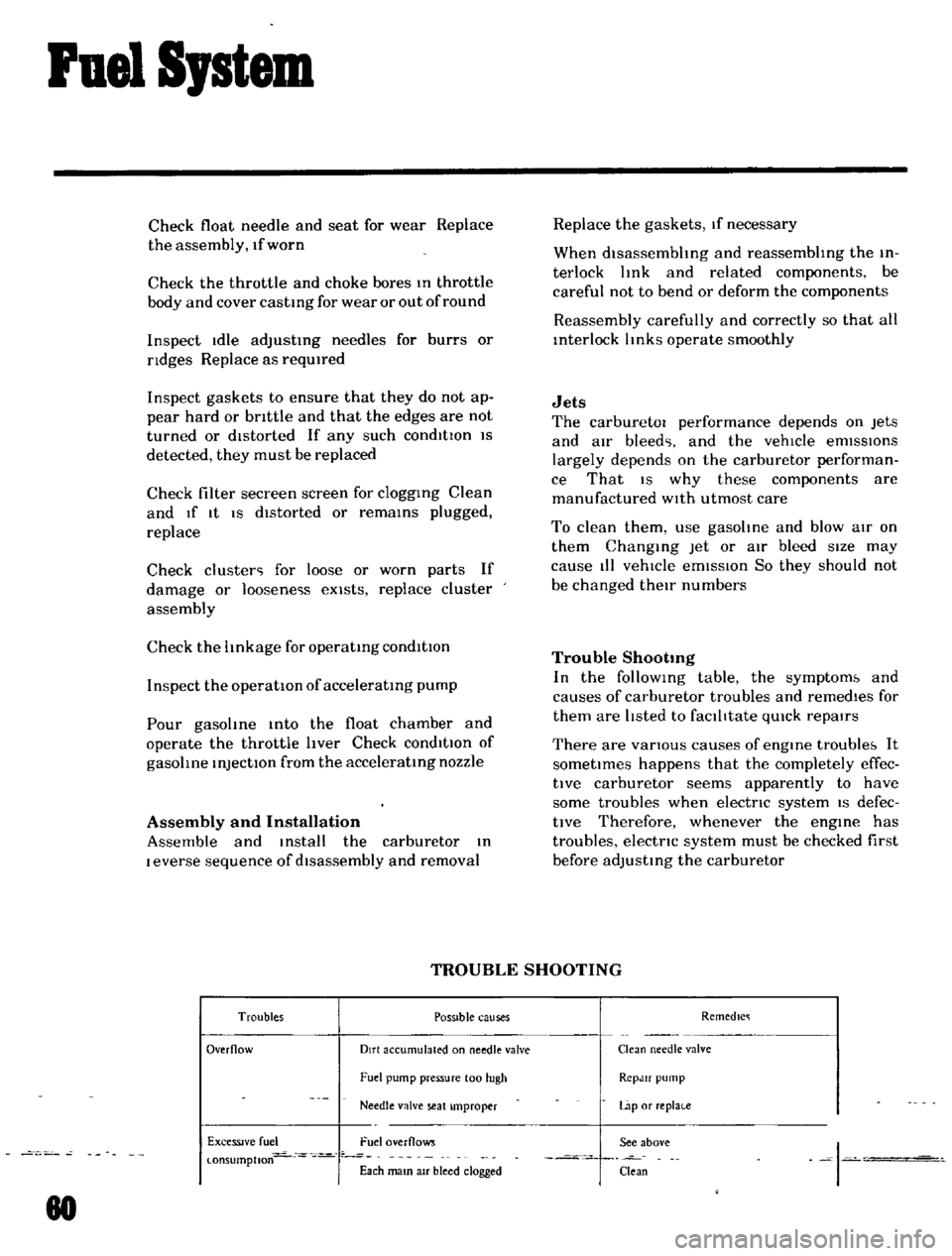
TROUBLE
SHOOTING
Troubles
POSSible
causes
Remedlc
Overflow
Dirt
accumulated
on
needle
valve
Clean
needle
valve
Fuel
pump
pressure
100
hIgh
RCpJlf
pump
Needle
valve
seat
Improper
Lap
or
replai
e
ExceSSIve
fuel
Fuel
overflows
See
above
I
l
onsumptlon
Each
mam
aIr
bleed
clogged
Clean
80
Page 75 of 136

Brakes
Thoroughly
Wipe
the
bleeder
screw
and
from
any
mud
or
dust
present
so
that
the
outlet
hole
IS
free
from
foreign
matter
Attach
a
VInyl
hose
to
the
wheel
cyhnder
bleeder
screw
Dip
the
end
of
the
VInyl
hose
In
a
Jar
contaInIng
some
brake
flUId
Depress
the
brake
pedal
two
to
three
times
and
keep
the
pedal
fully
depressed
With
the
brake
pedal
fully
depressed
loosen
the
bleeder
screw
exhaust
air
and
rettghten
the
bleeder
screw
qUIckly
Return
the
brake
pedal
slowly
Repeat
the
operatIons
above
Air
WIll
no
longer
come
out
from
the
bleeder
screw
but
brake
flUId
comes
out
When
atr
stIll
eXists
In
brake
flUId
It
appears
whIte
due
to
aIr
bub
ble
Conduct
aIr
bleedIng
on
other
wheel
cyhnders
In
the
same
manner
Note
a
Check
the
reservoir
for
fluid
level
during
bleeding
operation
b
FlUid
withdrawn
in
the
operation
should
not
be
used
refilling
bleeding
again
for
c
When
the
master
cylinder
is
dIsassem
bled
or
replaced
conduct
air
bleeding
on
the
wheel
cylinder
which
is
located
most
near
the
master
cyhnder
d
Ordinarily
air
bleeding
is
performed
in
the
following
sequence
Rear
left
Rear
right
Front
left
Front
right
e
Do
not
return
the
brake
pedal
before
retightening
the
bleeder
screw
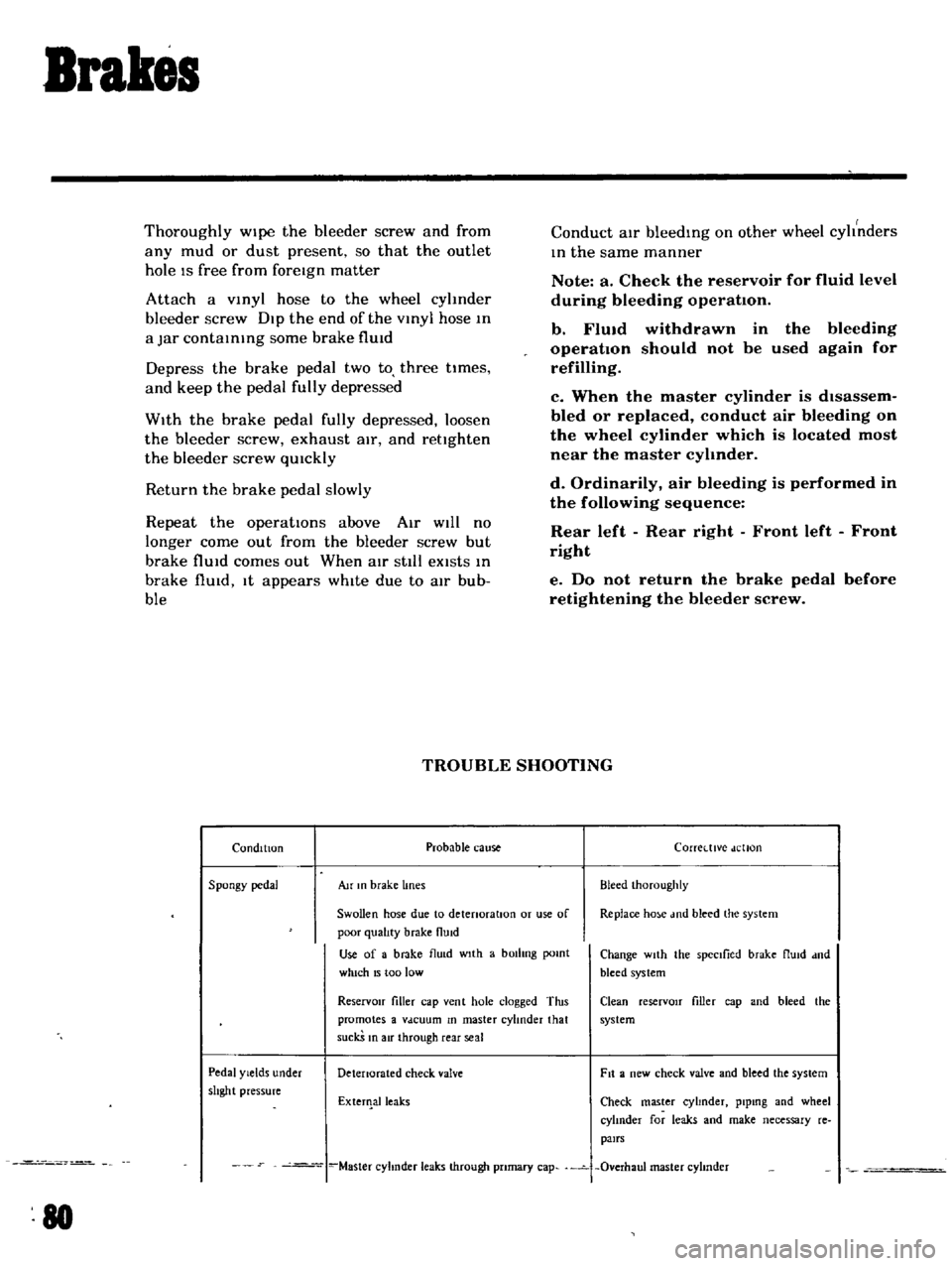
TROUBLE
SHOOTING
Condition
Probable
cause
Corretttve
dellon
Spongy
pedal
Au
In
brake
lines
Bleed
Ihoroughly
Swollen
hose
due
to
detenoratlOn
or
use
of
Replace
ho
e
md
bleed
the
system
poor
qualIty
brake
flUid
Use
of
a
brake
flu
d
wIth
a
bOilIng
pomt
Change
wIth
the
spectlied
brake
flUId
dnd
which
15
too
low
bleed
system
ReservOir
filler
cap
vent
hole
clogged
Tins
Clean
reserVOIr
filler
cap
and
bleed
the
promotes
a
Vdcuum
In
master
cylinder
that
system
suckS
In
air
through
rear
seal
Pedal
Yields
under
Detenorated
check
valve
Fit
a
new
check
valve
and
bleed
the
system
shght
pressure
ExterIlalleaks
Check
master
cyhnder
plpmg
and
wheel
cylInder
for
leaks
and
make
necessary
re
pairs
Master
cyhnder
leaks
through
pnmary
cap
Overhaul
master
cyhnder
80