1969 DATSUN B110 fuel filter
[x] Cancel search: fuel filterPage 4 of 136

able
of
Contents
MAINTENANCE
TUNE
UP
DIsassembly
32
InspectIOn
RepaIr
33
VALVE
CLEARANCES
6
AdJustmg
Regulator
33
ENGINE
OIL
6
Assembly
33
OIL
FILTER
7
COOLANT
7
COMPRESSION
7
ELECTRICAL
SYSTEM
BATTERY
8
IGNITION
TIMING
8
STARTER
36
DIstributor
Breaker
Pomt
9
Removal
37
Condenser
9
InstallatIOn
37
Spark
Plugs
9
Trouble
Shootmg
37
Carburetor
9
ALTERNATOR
36
Idle
LImIter
Cap
10
Removal
37
Dash
Pot
automatic
transmISSIOn
11
InstallatIOn
37
model
only
11
REGULATOR
39
Carburetor
Return
Sprmg
11
DeSCriptIOn
39
Fuel
Filter
11
Trouble
Shootmg
40
ENGINE
IGNITION
SYSTEM
DESCRIPTION
14
DISTRIBUTOR
44
REMOVAL
14
ConstructIOn
44
INSTALLATION
14
Checkmg
and
Adjustment
44
CLEANING
INSPECTION
14
SP
ARK
PLUGS
46
DISASSEMBL
Y
14
DeSCriptIOn
46
INSPECTION
REPAIR
18
InspectIOn
46
PreparatIOn
18
Cleamng
Regap
47
Cyltnder
Head
18
Valve
Assembly
18
Valve
Spnng
19
Valve
Rocker
Shaft
Rocker
Arm
19
FUEL
SYSTEM
Valve
LIfter
Push
Rod
20
Camshaft
Camshaft
Bearmg
20
FUEL
FILTER
50
Valve
Tlmmg
20
DESCRIPTION
50
Cyltnder
Block
21
REMOVAL
50
PIston
Piston
Pm
Plsto
LRmg
21
INSTALLATION
50
Connectmg
Rod
23
FUEL
PUMP
50
Crankshaft
24
DeSCriptIOn
50
Bushmg
Bearing
24
Testmg
51
Crankshaft
Sprocket
Removal
DIsassembly
52
Camshaft
Sprocket
25
InspectIOn
52
Flywheel
25
Assembly
52
ASSEMBL
Y
25
CARBURETOR
52
PrecautIOn
25
DeSCription
52
Cyltnder
Head
25
Adjustment
53
PIston
ConnectIng
Rod
26
Removal
58
Engme
26
DIsassembly
58
OIL
PUMP
32
Cleanmg
InspectIOn
59
Removal
Engme
m
vehicle
32
Assembly
InstallatIOn
60
I
Page 13 of 136
aiDtenuce
TUDe
up
Fig
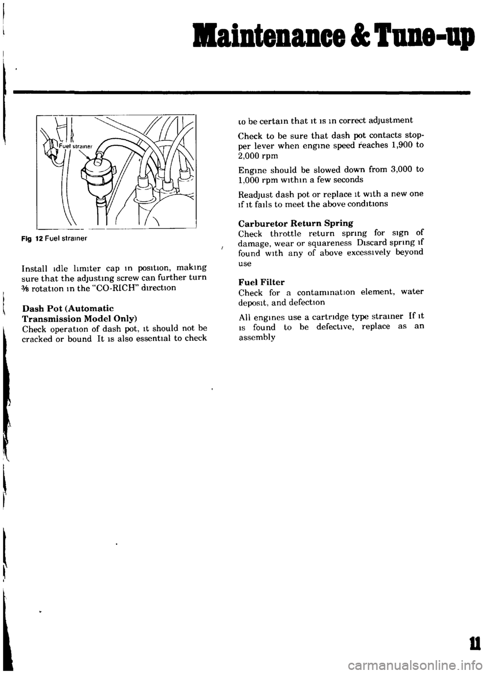
12
Fuel
strainer
Install
Idle
hmlter
cap
m
posItion
makmg
sure
that
the
adJustmg
screw
can
further
turn
rotatIOn
m
the
CO
RICH
d1rectlOn
Dash
Pot
Automatic
Transmission
Model
Only
Check
operation
of
dash
pot
It
should
not
be
cracked
or
bound
It
IS
also
essenttal
to
check
r
w
be
certam
that
It
IS
m
correct
adjustment
Check
to
be
sure
that
dash
pot
contacts
stop
per
lever
when
engme
speed
reaches
1
900
to
2
000
rpm
Engme
should
be
slowed
down
from
3
000
to
1
000
rpm
within
a
few
seconds
Readjust
dash
pot
or
replace
It
with
a
new
one
lflt
falls
to
meet
the
above
condItions
Carburetor
Return
Spring
Check
throttle
return
sprmg
for
sign
of
damage
wear
or
squareness
Discard
spring
If
found
wIth
any
of
above
excessIvely
beyond
use
Fuel
Filter
Check
for
a
contammatlOn
element
water
depoSIt
and
defection
All
engmes
use
a
cartridge
type
strainer
If
1t
IS
found
to
be
defective
replace
as
an
assembly
u
Page 31 of 136
BDgiDe
TIghtening
torque
40
to
43
ft
Ib
Install
the
push
rod
Install
the
rocker
haft
assembly
and
tighten
the
I
ocker
haft
bracket
bolts
to
the
specIfied
torque
Tightening
torque
15
to
18
ft
lb
Note
TIghtening
operation
should
be
made
gradually
10
separating
two
or
three
stages
and
outwardly
from
the
center
bracket
In
tall
the
Intake
and
exhaust
mamfolds
TIghtening
torque
65
to
10
ft
lb
AdJu
t
valve
clemance
wIth
the
specIfied
dlmenblOn
Install
the
rocker
cover
and
carburetor
assem
bly
I
n
tdll
the
watel
pump
and
thermostat
Tlghtemng
tOl
que
65
to
10
ft
lb
I
nstall
the
crankshaft
pulley
Tighten
the
crank
pulley
bolt
to
the
specIfied
torque
TIghtenIng
torque
109
to
116
ft
lb
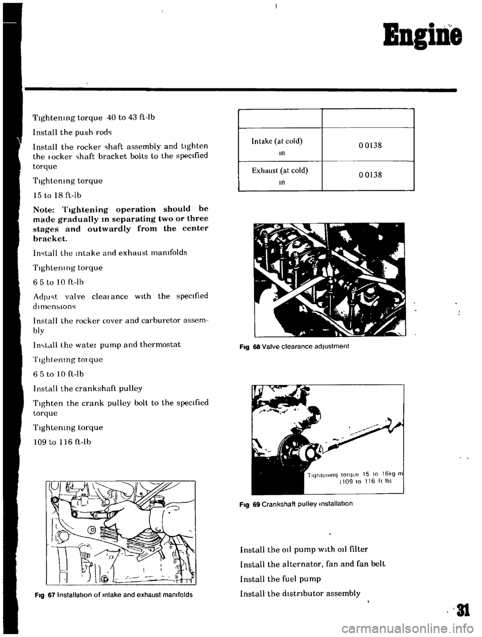
Fig
67
Installation
of
Intake
and
exhaust
manifolds
Intake
at
cold
00138
In
Exhaust
at
cold
00138
In
Fig
68
Valve
clearance
adjustment
TlqhtCnlnq
torque
15
to
16kg
m
109
to
116ltlb
Fig
69
Crankshaft
pulley
installation
Install
the
at
pump
with
011
filter
Install
the
alternator
fan
and
fan
belt
Install
the
fuel
pump
Install
the
dlstnbutor
assembly
31
Page 47 of 136
ruel
Sptem
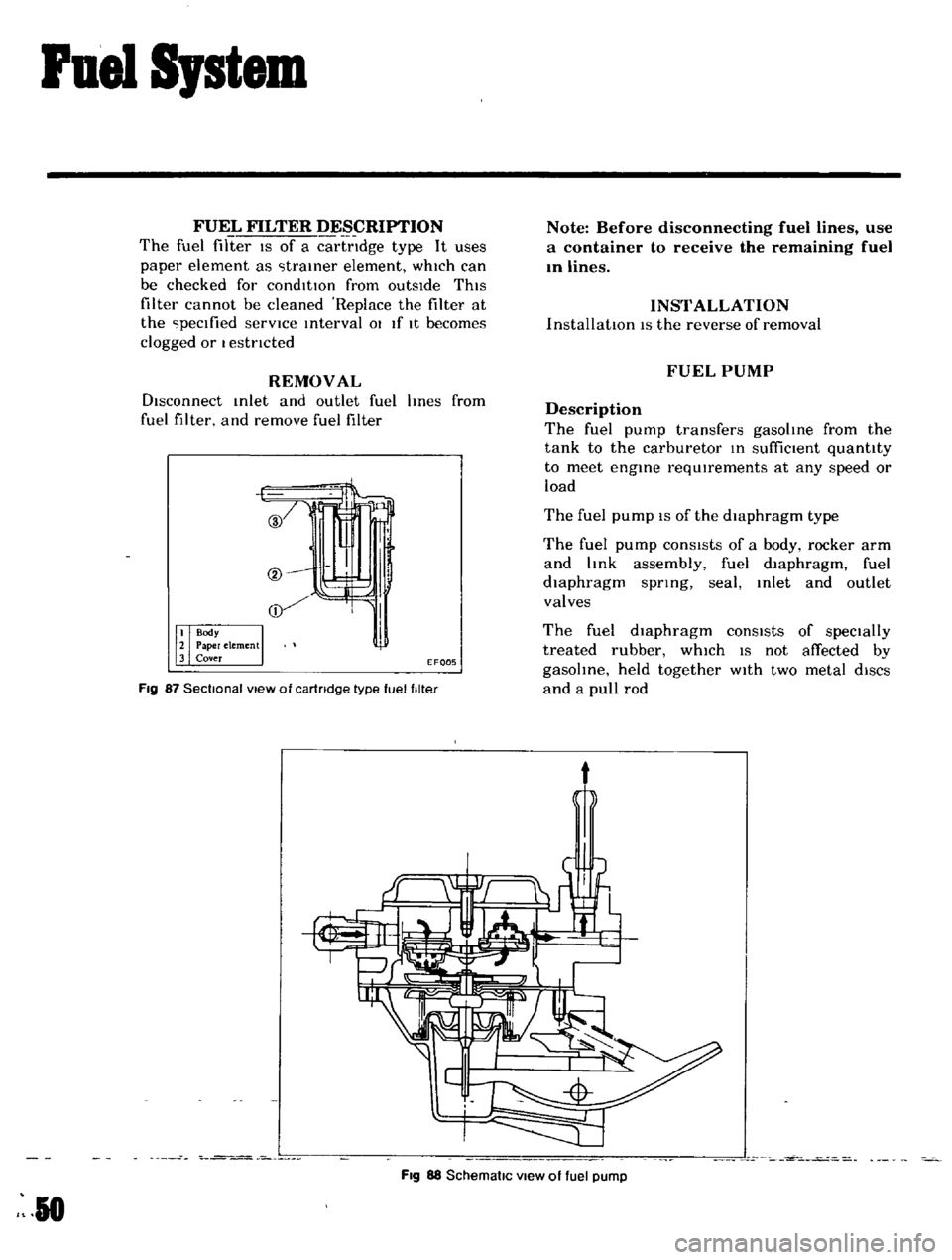
FUEL
FILTER
DESCRIPTION
The
fuel
filter
IS
of
a
cartndge
type
It
uses
paper
element
as
traIner
element
which
can
be
checked
for
condItIOn
from
outsIde
ThIS
filter
cannot
be
cleaned
Replace
the
filter
at
the
peclfied
servICe
Interval
01
If
It
becomes
clogged
or
I
estncted
REMOVAL
DIsconnect
Inlet
and
outlet
fuel
hnes
from
fuel
filter
and
remove
fuel
filter
if
EF005
Fig
87
Sectional
view
of
cartridge
type
fuel
filter
Note
Before
disconnecting
fuel
lines
use
a
container
to
receive
the
remaining
fuel
In
lines
INSTALLATION
InstallatIOn
IS
the
reverse
of
removal
FUEL
PUMP
Description
The
fuel
pump
transfers
gasoline
from
the
tank
to
the
carburetor
In
suffiCient
quantity
to
meet
engine
requIrements
at
any
speed
or
load
The
fuel
pump
IS
of
the
diaphragm
type
The
fuel
pump
conSIsts
of
a
body
rocker
arm
and
link
assembly
fuel
diaphragm
fuel
diaphragm
spnng
seal
Inlet
and
outlet
valves
The
fuel
diaphragm
consists
of
specially
treated
rubber
whIch
IS
not
affected
by
gasohne
held
together
WIth
two
metal
diSCS
and
a
pull
rod
t
Fig
88
SchematiC
view
of
fuel
pump
R
0
Page 49 of 136
Fuel
Sptem
Capacity
Test
The
capaclty
test
IS
used
only
when
the
statIc
plessure
IS
wlthm
specIficatIOns
The
capacity
test
IS
conducted
as
follows
Disconnect
the
fuel
p1pe
at
the
carburetor
Place
a
bUltable
contamer
at
the
end
of
the
pIpe
Start
the
engme
and
run
at
1
000
rpm
The
pump
should
delIver
1
US
pt
of
fuel
In
one
mmute
or
less
If
no
gasolme
or
only
a
lIttle
flows
flOm
open
end
of
pIpe
the
fuel
pIpe
IS
clogged
or
the
pump
I
malfunctlOntng
Before
removing
the
pump
remove
the
gas
tank
cap
dIsconnect
both
Inlet
dnd
outlet
pIpes
and
blow
through
them
wIth
an
aIr
hose
to
make
sure
that
they
are
clear
Thl
wIll
elImmate
pOSSible
clogged
gas
tramer
In
the
fuel
tank
Reconnect
the
pIpes
to
the
pump
and
rete
t
flow
Removal
and
DisassenbIy
Remove
the
fuel
pump
assembly
by
un
screwmg
two
mounting
nuts
and
dIsassemble
In
the
follOWing
order
Separate
the
upper
body
and
the
lower
body
by
unscrewmg
the
body
set
screws
Take
off
the
cap
and
the
cap
gasket
by
I
emOVIng
the
cap
screw
Unscrew
the
elbow
and
the
connector
Take
off
the
valve
retainer
by
unscrewmg
two
valve
retamer
screws
Two
valves
are
eaSIly
removed
To
remove
the
diaphragm
diaphragm
sprmg
lower
body
seal
washer
and
lower
body
seal
from
the
lower
body
press
down
the
dIaphragm
counter
to
the
force
of
the
dIaphragm
spring
and
while
dOIng
thIS
cant
the
dIaphragm
so
that
the
rectangular
part
m
the
lower
end
of
the
pull
rod
IS
unhooked
from
the
rocker
arm
lInk
Inspection
Check
the
upper
and
lower
bodIes
for
cracks
2
Check
the
valve
assembly
for
wear
of
the
valve
and
valve
sprmg
Blow
the
valve
assem
bly
by
breath
to
examme
ItS
functIOn
Check
the
dIaphragm
for
small
holes
cral
ks
and
wear
Check
the
rocker
dl
m
for
wear
at
the
portIOn
In
contact
With
the
camshaft
Check
the
rocker
arm
pin
for
wear
since
a
worn
pm
may
cause
011
leakage
Check
all
other
components
for
any
abnor
mahtIes
and
replace
With
new
parts
as
requIred
Assembly
Assembly
IS
done
In
reverse
order
of
disassem
bly
For
reassembly
and
remstallatlOn
the
followmg
matters
should
be
noted
Use
new
gasket
Lubricate
the
rocker
arm
link
rocker
arm
pm
and
lever
pm
before
mstallatlOlI
To
test
the
functIOn
poSItIOn
the
fuel
pump
assembly
about
33ft
above
fuel
level
WIth
a
pipe
connecting
the
fuel
pump
and
the
fuel
filter
and
operate
the
rocker
arm
by
hand
If
fuel
IS
drawn
up
soon
after
the
rocker
arm
IS
released
the
functIOn
of
the
pump
IS
satIsfactory
CARBURETOR
Description
The
carburetors
are
of
a
downdraft
type
whIch
IS
deSIgned
and
bUIlt
to
Increase
power
and
fuel
economy
as
well
as
to
reduce
the
em1SSlon
of
exhaust
gases
These
carburetors
present
several
dIstinct
features
of
Importance
to
the
car
owners
A
summary
of
features
IS
as
follows
Secondary
throttle
valve
IS
operated
by
throt
tie
lever
The
hIgh
power
and
good
ac
celeratIon
are
gained
With
combmatlOn
of
the
auxlhary
valve
Acceleratmg
pump
glves
excellent
ac
celeratIon
Page 57 of 136
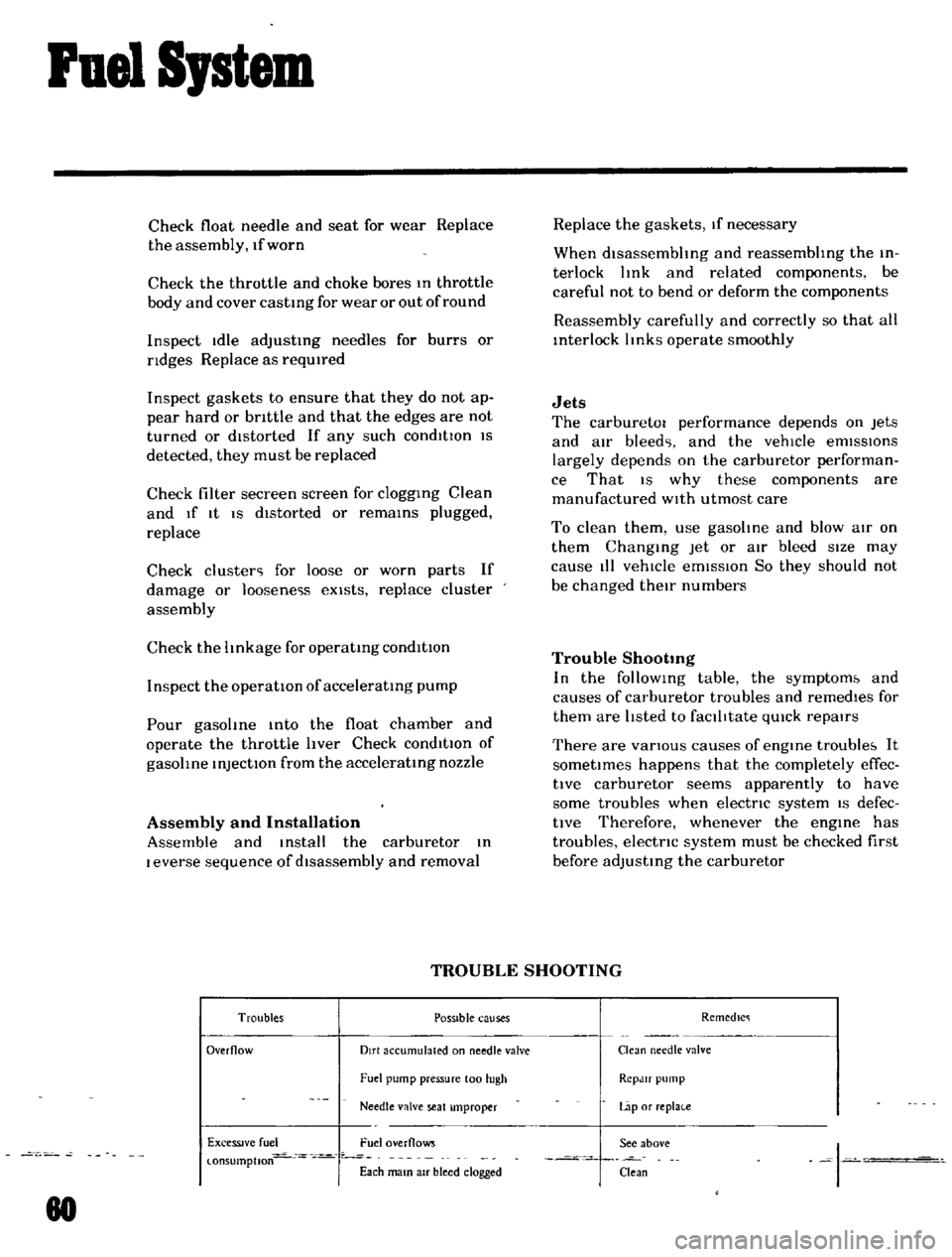
Fuel
SJstem
Check
float
needle
and
seat
for
wear
Replace
the
assembly
If
worn
Check
the
throttle
and
choke
bores
In
throttle
body
and
cover
castIng
for
wear
or
out
of
round
Inspect
Idle
adjustIng
needles
for
burrs
or
ndges
Replace
as
reqUIred
Inspect
gaskets
to
ensure
that
they
do
not
ap
pear
hard
or
bnttle
and
that
the
edges
are
not
turned
or
dIstorted
If
any
such
condItIOn
IS
detected
they
must
be
replaced
Check
filter
secreen
screen
for
cloggIng
Clean
and
If
It
IS
dIstorted
or
remaInS
plugged
replace
Check
cluster
for
loose
or
worn
parts
If
damage
or
Ioosene
s
eXists
replace
cluster
assembly
Check
the
hnkage
for
operatIng
condItion
Inspect
the
operatIOn
of
acceleratIng
pump
Pour
gasohne
Into
the
float
chamber
and
operate
the
throttle
hver
Check
conditIOn
of
gasohne
InjectIOn
from
the
acceleratIng
nozzle
Assembly
and
Installation
Assemble
and
Install
the
carburetor
In
I
everse
sequence
of
dIsassembly
and
removal
Replace
the
gaskets
If
necessary
When
dlsassembhng
and
reassembhng
the
In
terlock
hnk
and
related
components
be
careful
not
to
bend
or
deform
the
components
Reassembly
carefully
and
correctly
so
that
all
Interlock
hnks
operate
smoothly
Jets
The
carburetor
performance
depends
on
Jets
and
aIr
bleed
and
the
vehicle
emISSIOns
largely
depends
on
the
carburetor
performan
ce
That
IS
why
these
components
are
manufactured
WIth
utmost
care
To
clean
them
use
gasohne
and
blow
aIr
on
them
ChangIng
Jet
or
air
bleed
sIze
may
cause
III
vehICle
emIssIon
So
they
should
not
be
changed
theIr
numbers
Trouble
Shootmg
In
the
follOWIng
table
the
symptom
and
causes
of
carburetor
troubles
and
remedIes
for
them
are
hsted
to
faclhtate
qUIck
repaIrs
There
are
vanous
causes
of
engIne
trouble
It
sometImes
happens
that
the
completely
effec
tlve
carburetor
seems
apparently
to
have
some
troubles
when
electnc
systern
IS
defec
tIve
Therefore
whenever
the
engIne
has
troubles
electnc
system
must
be
checked
first
before
adjusting
the
carburetor
TROUBLE
SHOOTING
Troubles
POSSible
causes
Remedlc
Overflow
Dirt
accumulated
on
needle
valve
Clean
needle
valve
Fuel
pump
pressure
100
hIgh
RCpJlf
pump
Needle
valve
seat
Improper
Lap
or
replai
e
ExceSSIve
fuel
Fuel
overflows
See
above
I
l
onsumptlon
Each
mam
aIr
bleed
clogged
Clean
80
Page 132 of 136
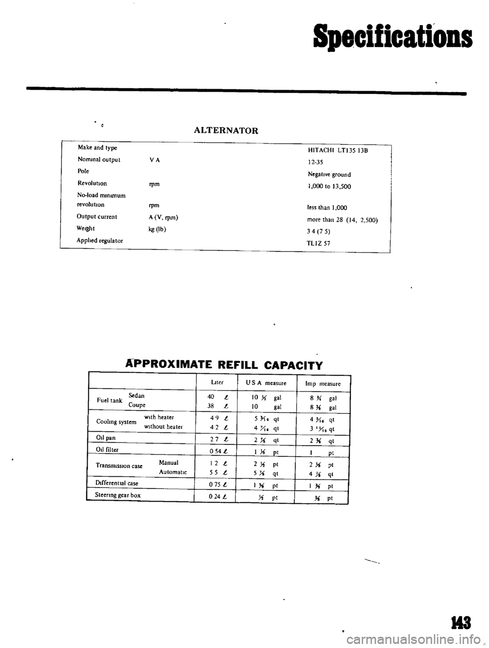
Specifications
ALTERNATOR
Make
and
type
NonunaJ
output
VA
Pole
Revolution
rpm
No
load
mmunum
revolu
bon
rpm
Output
current
A
V
rpm
Weight
kg
lb
Applied
regulator
HITACHI
LTl3S
13B
12
35
NegatIve
ground
1
000
to
13
500
less
than
I
000
more
than
28
14
2
500
34
7
5
TLI
Z
57
APPROXIMATE
REFILL
CAPACITY
Dter
USA
measure
lmp
measure
Sedan
40
t
10
X
gal
8Y
gal
Fuel
tank
Coupe
38
t
10
gal
8
gal
with
heater
49
t
5
X
qt
4
X
qt
Coohng
system
without
heater
42
t
4
yt
qt
3
X
qt
Od
pan
27
t
2X
ql
2
qt
Od
filter
054
t
IX
pt
I
pi
Transmission
case
Manual
12
t
2X
pt
2X
t
Automatic
55
t
5X
qt
4X
ql
Dlfferenttal
case
o
75
t
I
pI
IX
pI
Steenng
gear
box
024
L
X
pi
X
pt
H3