1969 DATSUN B110 wheel bolt torque
[x] Cancel search: wheel bolt torquePage 27 of 136
Bogine
Note
Set
the
locate
plate
so
as
the
LOWER
mark
comes
to
the
engine
bot
tom
side
Set
the
maIn
bearIngR
on
theIr
posItIOns
on
the
cylinder
block
Notes
a
The
center
bearmg
No
3
bearmg
is
a
flanged
type
for
thrust
force
b
Two
lOner
bearmgs
No
2
and
No
4
are
of
the
same
type
c
The
front
bearmg
No
1
IS
the
same
type
as
the
rear
bearmg
No
5
d
All
bearings
except
for
No
I
bearing
are
interchangeable
between
upper
and
lower
bearings
Apply
engIne
OIl
to
the
mam
bearIng
surfaces
on
both
sIdes
of
the
cyltnder
block
and
cap
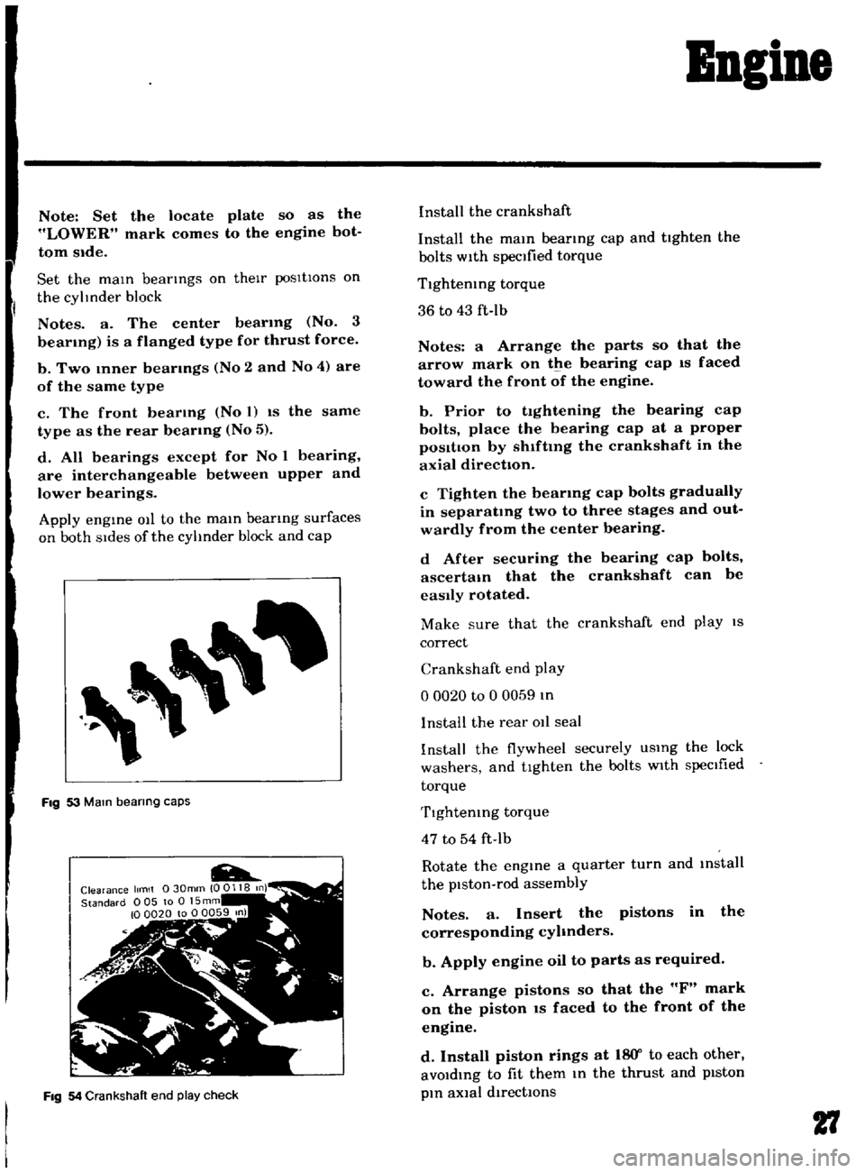
Fig
53
Mam
bearing
caps
Fig
54
Crankshaft
end
play
check
Install
the
crankshaft
Install
the
mam
bearmg
cap
and
tighten
the
bolts
with
specified
torque
Tlghtemng
torque
36
to
43
ft
Ib
Notes
a
Arrange
the
parts
so
that
the
arrow
mark
on
the
bearing
cap
IS
faced
toward
the
front
of
the
engine
b
Prior
to
tightening
the
bearing
cap
bolts
place
the
bearing
cap
at
a
proper
posItIon
by
shlftmg
the
crankshaft
in
the
axial
direction
c
Tighten
the
bearmg
cap
bolts
gradually
in
separatmg
two
to
three
stages
and
out
wardly
from
the
center
bearing
d
After
securing
the
bearing
cap
bolts
ascertam
that
the
crankshaft
can
be
easily
rotated
Make
sure
that
the
crankshaft
end
play
IS
correct
Crankshaft
end
play
o
0020
to
0
0059
In
I
nstalI
the
rear
011
seal
Install
the
flywheel
securely
USIng
the
lock
washers
and
tighten
the
bolts
with
specIfied
torque
Tlghtemng
torque
47
to
54
ft
Ib
Rotate
the
engine
a
quarter
turn
and
mstall
the
piston
rod
assembly
Notes
a
Insert
the
pistons
in
the
corresponding
cyhnders
b
Apply
engine
oil
to
parts
as
required
c
Arrange
pistons
so
that
the
F
mark
on
the
piston
IS
faced
to
the
front
of
the
engine
d
Install
piston
rings
at
18
Y
to
each
other
avoIdIng
to
fit
them
In
the
thrust
and
pIston
pIn
aXial
directIOns
27
Page 69 of 136
Brakes
c
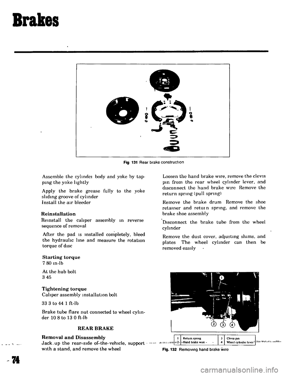
Fig
131
Rear
brake
construction
Assemble
the
cylIndel
body
and
yoke
by
tap
ping
the
yoke
lIghtly
Apply
the
brake
grease
fully
to
the
yoke
slIding
groove
of
cylInder
I
nstall
the
air
bleeder
Reinstallation
Reinstall
the
calIper
assembly
In
reverse
sequence
of
removal
After
the
pad
IS
Installed
completely
bleed
the
hydraulIc
line
and
measure
the
rotatton
torque
of
diSC
Starting
torque
780
In
Ib
At
the
hub
bolt
345
Tightening
torque
CalIper
assembly
installatIOn
bolt
33
3
to
44
1
ft
lb
Brake
tube
flare
nut
connected
to
wheel
cylIn
der
108
to
13
0
ft
lb
REAR
BRAKE
Removal
and
Disassembly
Jack
up
the
rear
slde
of
the
vehicle
support
With
a
stand
and
remove
the
wheel
74
Loosen
the
hand
brake
Wire
remove
the
cleVIS
pin
from
the
rear
wheel
l
ylInder
lever
and
disconnect
the
hand
brake
wIre
Remove
the
return
spnng
pull
spnng
Remove
the
brake
drum
Remove
the
shoe
retainer
and
retUl
n
spnng
and
remove
the
brake
shoe
assembly
DIsconnect
the
brake
tube
from
the
wheel
cylinder
Remove
the
dust
cover
adjusting
shims
and
plates
The
wheel
cylInder
can
then
be
removed
eaSily
Flg
132
RemOVing
hand
brake
vme
Page 85 of 136
SteeriDg
ConditIon
lIeavy
steering
Loose
steenng
Pull
to
one
side
Steermg
shock
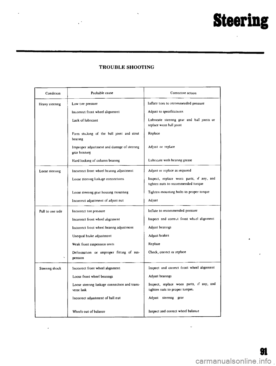
TROUBLE
SHOOTING
Probable
cause
Low
tIre
pressure
In
orreet
front
wheel
altgnmcnt
Lack
of
lubricant
FITm
stll
kmg
of
the
ball
Jomt
and
strut
beanog
Improper
adjustment
and
damage
of
steering
gcar
housmg
H
Hd
lock1l1g
of
column
beanng
Incorrect
front
wheel
be
mng
ddJustment
Loose
steermg
hnkJge
connectIOns
Loose
steermg
gCdf
housmg
mountIng
Incorrect
adjustment
of
ddJust
nut
Incorrect
lITe
pre
sure
Incorrect
front
wheel
dhgnment
Incorrect
front
wheel
beanng
adjustment
Unequal
brdke
ddJustment
Weak
front
suspensIOn
umts
Deformation
or
Improper
fittmg
of
sus
pensIOn
Incorrect
front
wheel
ahgnment
Loose
front
wheel
beanngs
Loose
steering
lmkage
connectIOn
and
trans
verse
lmk
Incorrect
adjustment
of
ball
nut
Wheels
out
of
balance
Corrective
action
Innate
tires
to
recommended
pressure
Adjust
to
speclficatJono
Lubricate
steering
gc
H
and
b
dl
jomts
or
replace
WOln
bdll
jomt
Replace
Adjust
or
repldce
LubrlcJte
with
bearing
grease
Adjust
or
replace
as
reqUired
Inspect
replace
worn
pdrts
If
any
and
tighten
nuts
to
recommended
torque
TIghten
mountmg
bolts
to
proper
torque
Adjust
Inflate
to
recommended
pressurc
Inspect
and
corred
front
WhlCI
alignment
Adjust
bearings
Adjust
brakes
Replace
Check
correct
or
replace
Inspect
and
correct
front
wheel
alIgnment
Adjust
bearings
Inspect
replace
worn
parts
If
any
and
tighten
nuts
to
proper
torque
Adjust
steenng
gear
Inspect
and
correct
wheel
balanl
e
81
Page 88 of 136
Bear
Drive
Suspension
A
correct
contact
pattern
means
that
It
beii
the
ange
of
2
3
to
3
4
from
the
tip
of
the
tooth
nder
no
load
Backlash
IS
010
to
015mm
00039
to
00059
n
Tlghtemng
torque
of
drlve
gear
bolt
60
to
70
kg
m
434
to
506
ft
Ibl
TIghten
by
tapping
bolt
head
with
a
0
lkg
1
4
lb
hammer
TIghtening
torque
of
dnvt
pmlon
nut
12
to
11
kg
m
86
8
to
1229
ft
lb
Plmon
be
nng
adjust
spacer
O
lve
plmon
adlustlng
washer
T
W
N
HxO
011
0
2
mml
T
T
Drive
gear
ad
ustlng
shims
Left
Ide
T1
jA
C
0
H
I
001
0200
E
lmml
Right
SIde
T2
B
D
HI
001
0
200
F
mml
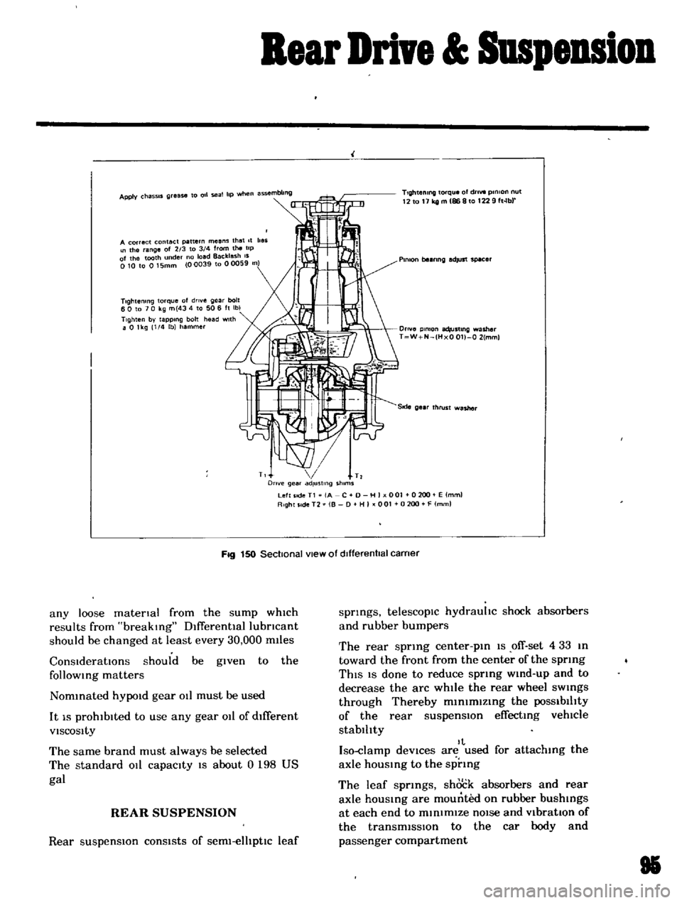
Fig
150
Sectional
view
of
dIfferentIal
carner
any
loose
matenal
from
the
sump
which
results
from
breaking
Dlfferentlallubncant
should
be
changed
at
least
every
30
000
m11es
ConsIderatIOns
should
be
given
to
the
follOWing
matters
Nommated
hYPOld
gear
011
must
be
used
It
IS
prohibited
to
use
any
gear
011
of
dIfferent
VISCOSity
The
same
brand
must
always
be
selected
The
standard
011
capacity
IS
about
0
198
US
gal
REAR
SUSPENSION
Rear
suspensIOn
consists
of
serm
elhptlc
leaf
springs
telescopIc
hydrauhc
shock
absorbers
and
rubber
bumpers
The
rear
sprmg
center
pm
1S
ofT
set
4
33
m
toward
the
front
from
the
center
of
the
sprmg
ThIS
IS
done
to
reduce
sprmg
wmd
up
and
to
decrease
the
arc
while
the
rear
wheel
sWings
through
Thereby
m1n1mlzmg
the
POSSibilIty
of
the
rear
suspensIOn
effecting
vehlCle
stablhty
It
Iso
damp
deVices
are
used
for
attachmg
the
axle
hOUSing
to
the
sprmg
The
leaf
sprmgs
shock
absorbers
and
rear
axle
housmg
are
mounted
on
rubber
bushings
at
each
end
to
minimIZe
nOIse
and
VibratIOn
of
the
transmiSSIon
to
the
car
body
and
passenger
compartment
85
Page 120 of 136
Specifications
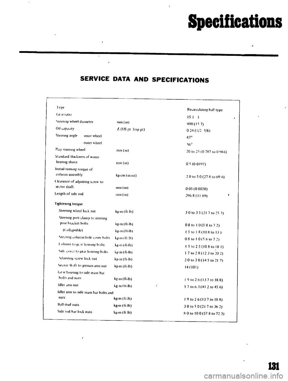
SERVICE
DATA
AND
SPECIFICATIONS
1
vpc
RCl
n
ulatlllg
bdll
type
ClrrJtm
Ieertng
wheel
dldl1lCler
Od
JpJuty
iteenng
angle
IImer
wheel
outer
heel
PIdY
Ieermg
wheel
tJJ
d
ud
thl
kness
of
worm
beaTIng
shulls
hllttal
turnmg
torque
of
column
assembly
le
Hance
uf
ddJustmg
SLrew
to
sedor
shaft
Length
of
side
rod
TlghteolOg
torque
Steenng
wheellol
k
nul
Steenng
po
t
d
unp
to
steermg
pO
1
hr
H
lct
holts
llIlJp
ihlc
C
lrtng
llImn
hole
over
hnlt
IllImn
10
L
If
hOUI
IIl
holts
tdt
t
f
III
ge
lf
hou
lIl
holh
dlu
m
l
rew
m
nut
edM
h
If
I
10
plllllJIl
drill
nut
If
hOll
lI1g
In
Side
I1MIIl
bar
holt
Jlld
nut
Idler
dflll
nul
Idler
arm
to
stde
l1lJlO
bar
bolts
Jnd
nuts
B
III
stud
nuts
51dc
rod
hJf
IOl
k
nuts
mm
m
15
I
400
7
024
1
211
L
US
pI
Imp
pt
43
1
16
111111
111
20
to
2
10
7X7
to
0
JX4
mm
m
OS
0
0197
kg
cm
lIl
oz
2
0
to
5
0
27
X
10
69
4
mm
m
005
0
0020
296
8
1169
nun
Ill
kg
Ill
ft
Ihl
3
0
10
3
5
I
7
10
2
S
1
kg
m
ft
Ih
kg
Ill
ft
Ih
kg
Ill
I
ft
Ih
kg
Ill
ft
Ib
kg
Ill
ft
Ih
kg
m
ft
Ih
kg
m
ft
Ih
08
to
I
0
5
8
107
15
to
18
108
to
13
I
o
8
10
I
0
S
X
to
7
I
1
5
to
2
5
10810
18
I
7
10
2
8
12
3
10
20
2
201030
14510217
14
101
kg
Ill
ft
Ib
kg
mltt
Ih
I
9
to
2
6
13
7
to
18
8
5
7
106
3
4
2
1045
6
kg
m
ft
Ib
kg
m
ft
Ib
kg
Ill
ft
Ih
191026
13710188
30
to
0
21
7
to
36
2
XOlo
100
57810723
I3l
Page 123 of 136
Specifications
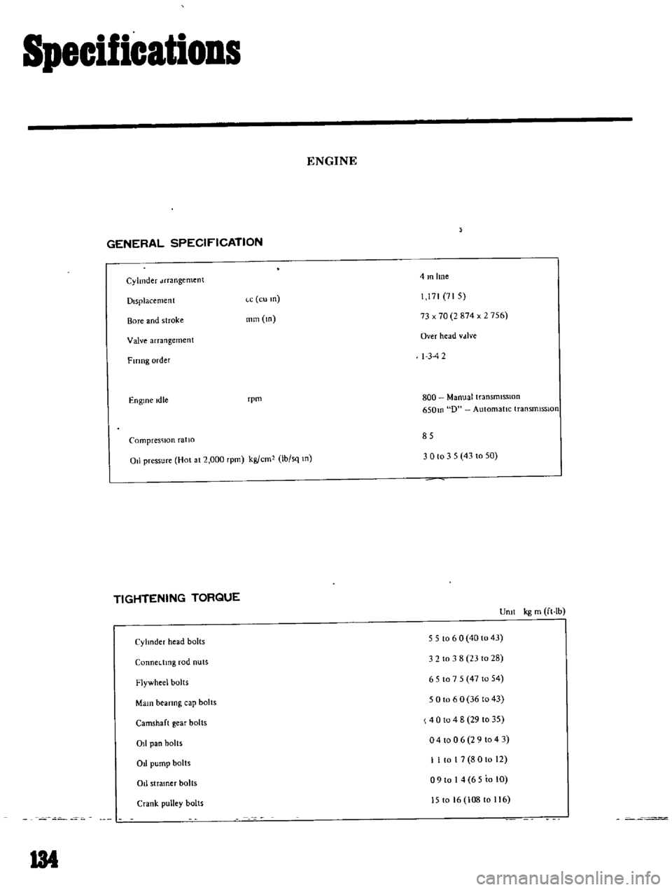
ENGINE
GENERAL
SPECIFICATION
Cylinder
Jrrangement
4mlme
Displacement
ce
eu
m
71
71
5
Bore
and
stroke
mm
m
73
x
70
2
874
x
2
756
Valve
arrangement
Over
head
vdlve
Fmng
order
I
3
42
Engine
Idle
rpm
800
Manual
transmiSSIOn
650m
D
Automatic
transrmsslon
Compresc
lon
ratio
85
011
pressure
Hol
al
2
000
rpm
kg
em
Ib
sq
m
3
0
to
3
5
43
10
50
TIGHTENING
TORQUE
Uml
kg
m
ft
Ib
Cyhnder
head
bolts
5
5
10
6
0
40
10
43
3
2
to
3
8
2310
28
CQnnedmg
rod
nuts
Flywheel
bolls
651075
471054
Main
bearing
cap
bolts
5
0
10
6
0
36
to
43
4
0
10
4
8
29
10
35
o
4
to
0
6
2
9
1043
Camshaft
gear
bolts
011
pan
bolts
Ot
pump
bolts
1
I
to
I
7
8
0
10
12
o
9
to
I
4
65
to
lO
J5
to
16
108
to
116
011
stramer
bolts
Crank
pulley
bolts
134