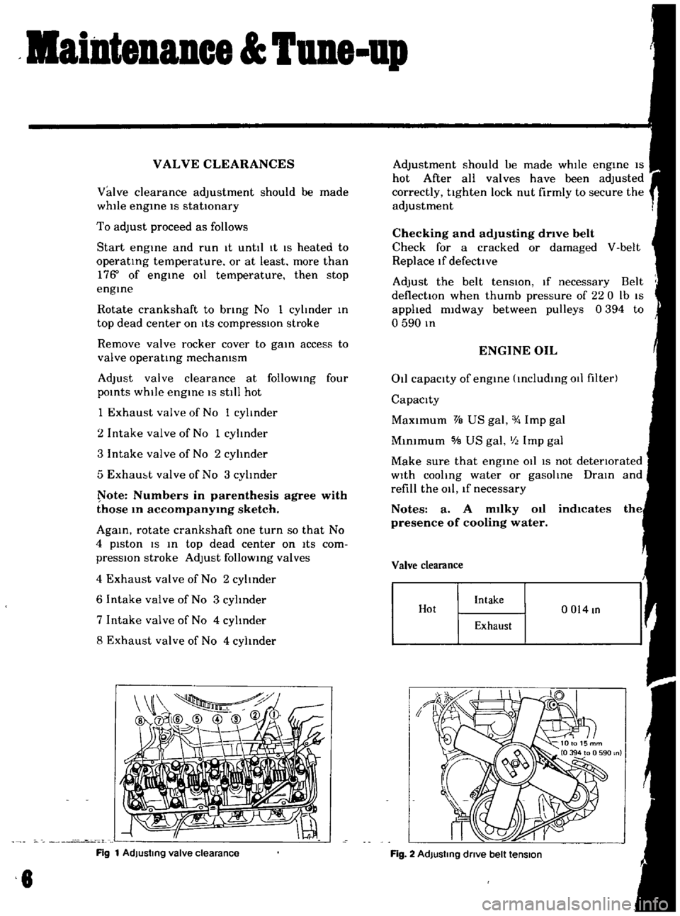
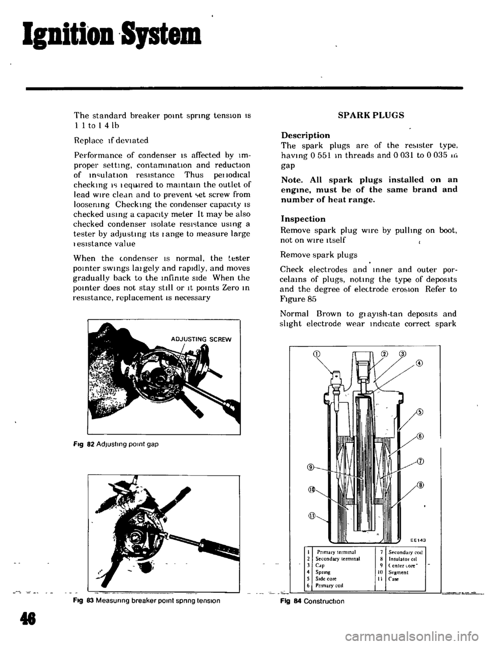
Page 8 of 136

ainteDaDee
TUDe
up
VAL
VE
CLEARANCES
Valve
clearance
adjustment
should
be
made
while
engme
IS
stationary
To
adjust
proceed
as
follows
Start
engme
and
run
It
until
It
IS
heated
to
operatIng
temperature
or
at
least
more
than
17S
of
engIne
011
temperature
then
stop
engIne
Rotate
crankshaft
to
bnng
No
1
cylInder
In
top
dead
center
on
ItS
compressIOn
stroke
Remove
valve
rocker
cover
to
gaIn
access
to
valve
operatIng
mechamsm
Adjust
valve
clearance
at
follOWing
four
pOints
while
engIne
IS
still
hot
1
Exhaust
valve
of
No
1
cylinder
2
Intake
valve
of
No
1
cylinder
3
Intake
valve
of
No
2
cylinder
5
Exham
t
valve
of
No
3
cylInder
ote
Numbers
in
parenthesis
agree
with
those
10
accompanY1Og
sketch
AgaIn
rotate
crankshaft
one
turn
so
that
No
4
piston
IS
In
top
dead
center
on
ItS
com
pressIOn
stroke
Adjust
follOWIng
valves
4
Exhaust
valve
of
No
2
cylinder
6
Intake
valve
of
No
3
cylinder
7
Intake
valve
of
No
4
cylInder
8
Exhaust
valve
of
No
4
cylinder
Rg
1
AdJustmg
valve
clearance
8
Adjustment
should
ue
made
whIle
engIne
IS
hot
After
all
valves
have
been
adjusted
correctly
tighten
lock
nut
firmly
to
secure
the
adjustment
Checking
and
adjusting
drive
belt
Check
for
a
cracked
or
damaged
V
belt
Replace
If
defective
Adjust
the
belt
tenSIOn
If
necessary
Belt
deflectIOn
when
thumb
pressure
of
220
Ib
IS
applied
midway
between
pulleys
0394
to
o
590
In
ENGINE
OIL
011
capacity
of
engIne
IncludIng
011
filter
Capacity
MaXimum
VB
US
gal
Imp
gal
MInimum
5IB
US
gal
III
Imp
gal
Make
sure
that
engIne
011
IS
not
detenorated
With
cooling
water
or
gasolIne
DraIn
and
refill
the
011
lf
necessary
Notes
a
A
m1lky
011
indlcates
presence
of
cooling
water
Valve
clearance
Hot
Intake
0014
In
Exhaust
Fig
2
AdJustmg
dnve
belt
tension
Page 44 of 136

Ignition
Sptem
The
standard
breaker
pOint
spring
tensIOn
IS
1
1
to
1
4
lb
Replace
If
devIated
Performance
of
condenser
IS
affected
by
Im
proper
setting
contaminatIOn
and
reductIOn
of
In
ulatlOn
resIstance
Thus
pellOdlcal
checking
I
I
eqlJ
lred
to
maintain
the
outlet
of
lead
wire
clean
and
to
prevent
et
screw
from
loosening
Checking
the
condenser
capacIty
IS
checked
USing
a
capacity
meter
It
may
be
also
checked
condenser
Isolate
resl
tance
USing
a
tester
by
adjusting
ItS
I
ange
to
measure
large
I
eSlstance
value
When
the
condenser
IS
normal
the
tester
pOinter
SWings
1m
gely
and
rapIdly
and
moves
gradually
back
to
the
Infimte
SIde
When
the
pOinter
does
not
stay
stili
or
It
points
Zero
In
reSIstance
replacement
IS
necessary
Fig
82
AdJusllng
POint
gap
Fig
83
Measunng
breaker
POint
spnng
tension
g
SPARK
PLUGS
Description
The
spark
plugs
are
of
the
re
lster
type
haVing
0
551
In
threads
and
0031
to
0035
11i
gap
Note
All
spark
plugs
installed
on
an
engme
must
be
of
the
same
brand
and
number
of
heat
range
Inspection
Remove
spark
plug
wIre
by
pulhng
on
boot
not
on
WIre
Itself
Remove
spark
plugs
Check
electrodes
and
Inner
and
outer
por
celams
of
plugs
noting
the
type
of
depOSits
and
the
degree
of
electrode
erO
lOn
Refer
to
Figure
85
Normal
Brown
to
gl
aYlsh
tan
depoSits
and
shght
electrode
wear
indIcate
correct
spark
@
I
Pnmary
terminal
2
Secondary
terminal
3
Cdp
4
Sprang
5
SIde
core
6
Prrmary
coil
7
Secondary
COIl
8
Insulator
011
9
enter
lore
10
Segment
II
Case
Fig
84
Construction
Page 134 of 136
i
r
1
ill
j
f
f
c
1
dii
s
f
DISTRIUTOR
llle
Ij
Ai
r
t
Make
and
type
D412
80
for
Manual
Transmission
D4
I
2
89
for
Automapc
Transmission
f
I
r
7I
i
Fmng
order
I
3
4
2
13
42
Rotatmg
directIOn
Counterclockwise
Counterclockwise
Dwell
angle
49
550
49
550
Condenser
capacity
I1F
o
20
to
0
24
o
20
to
0
24
IGNITION
COIL
j
MJk
e
mu
lVpc
Pllll1
llY
voliJge
v
HANSHIN
HITACHI
H5
152
C6R
601
12
12
more
than
7
more
t
1
an
7
028
028
17
to
I
43
I
I7
to
I
43
J
112
to
168
112
to
168
13
to
I
7
13
to
I
7
RC
15
5560R
1510
f
park
gJp
mm
m
l
lIlllJry
reSI
itdnLe
at
20o
680F
n
Seu1ndJry
rcc
lc
lllll
e
Jt
Oo
68f
F
Kn
l
tlrllJl
resistor
Jt
200
68uF
n
Applied
ft
SISlor
l
l
t
t
U
1
j
1
h
r
r
1
J
T
I
oj
f
a
11
JJf
iF
t
r
4
k
U
M
JL
ti
A
z
jy
L
Io
l
k
rt
Url