1969 DATSUN B110 checking oil
[x] Cancel search: checking oilPage 8 of 136

ainteDaDee
TUDe
up
VAL
VE
CLEARANCES
Valve
clearance
adjustment
should
be
made
while
engme
IS
stationary
To
adjust
proceed
as
follows
Start
engme
and
run
It
until
It
IS
heated
to
operatIng
temperature
or
at
least
more
than
17S
of
engIne
011
temperature
then
stop
engIne
Rotate
crankshaft
to
bnng
No
1
cylInder
In
top
dead
center
on
ItS
compressIOn
stroke
Remove
valve
rocker
cover
to
gaIn
access
to
valve
operatIng
mechamsm
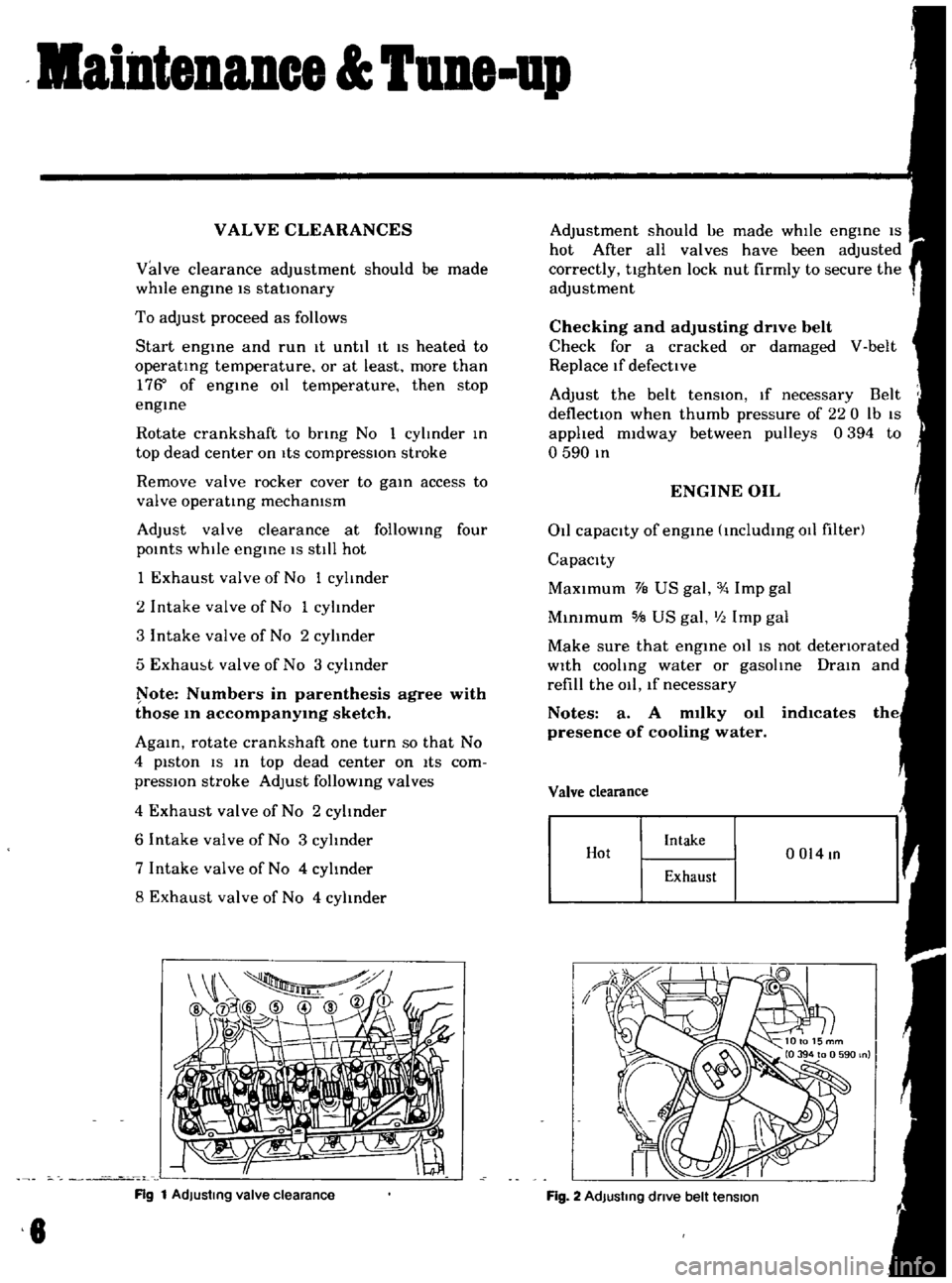
Adjust
valve
clearance
at
follOWing
four
pOints
while
engIne
IS
still
hot
1
Exhaust
valve
of
No
1
cylinder
2
Intake
valve
of
No
1
cylinder
3
Intake
valve
of
No
2
cylinder
5
Exham
t
valve
of
No
3
cylInder
ote
Numbers
in
parenthesis
agree
with
those
10
accompanY1Og
sketch
AgaIn
rotate
crankshaft
one
turn
so
that
No
4
piston
IS
In
top
dead
center
on
ItS
com
pressIOn
stroke
Adjust
follOWIng
valves
4
Exhaust
valve
of
No
2
cylinder
6
Intake
valve
of
No
3
cylinder
7
Intake
valve
of
No
4
cylInder
8
Exhaust
valve
of
No
4
cylinder
Rg
1
AdJustmg
valve
clearance
8
Adjustment
should
ue
made
whIle
engIne
IS
hot
After
all
valves
have
been
adjusted
correctly
tighten
lock
nut
firmly
to
secure
the
adjustment
Checking
and
adjusting
drive
belt
Check
for
a
cracked
or
damaged
V
belt
Replace
If
defective
Adjust
the
belt
tenSIOn
If
necessary
Belt
deflectIOn
when
thumb
pressure
of
220
Ib
IS
applied
midway
between
pulleys
0394
to
o
590
In
ENGINE
OIL
011
capacity
of
engIne
IncludIng
011
filter
Capacity
MaXimum
VB
US
gal
Imp
gal
MInimum
5IB
US
gal
III
Imp
gal
Make
sure
that
engIne
011
IS
not
detenorated
With
cooling
water
or
gasolIne
DraIn
and
refill
the
011
lf
necessary
Notes
a
A
m1lky
011
indlcates
presence
of
cooling
water
Valve
clearance
Hot
Intake
0014
In
Exhaust
Fig
2
AdJustmg
dnve
belt
tension
Page 9 of 136

aintenIDce
une
up
Find
the
cause
for
necessary
corrective
action
b
Oil
with
extremely
low
viscosity
in
dicates
dllutton
with
gasoline
Check
011
level
If
found
below
L
mark
refill
to
H
mark
on
gauge
OIL
FILTER
The
011
filter
IS
of
a
cartndge
type
Check
for
011
leaks
through
gasketed
flange
If
any
leakage
IS
found
retIghten
shghtly
If
nece
sary
replaLe
filter
as
an
assembly
When
mstalhng
an
011
filter
tIghten
by
hand
Note
Do
not
overtighten
011
fIlter
or
oil
leakage
may
result
I
I
Fig
3
Checking
engine
011
level
Oc
OF
I
0
121
20141
30
21
401401
5015BI
I
EGOQl
I
10
20
Fig
4
Protection
concentration
COOLANT
L
L
C
IS
al
ethylene
glycol
base
product
con
tammg
chemical
mhlbltors
to
protect
the
coohng
system
from
rustmg
and
corrosIOn
The
L
I
C
does
not
con
tam
any
glycerme
ethyl
or
methyl
alcohol
It
wIll
not
evaporate
or
bOll
away
and
can
be
used
wIth
either
high
or
low
temperature
thermostat
It
flows
freely
transfers
heat
effiCiently
and
will
not
clog
the
passages
m
the
coohng
system
The
L
L
C
must
not
be
mIxed
wIth
other
products
ThiS
coolant
can
be
used
throughout
the
seasons
of
the
year
Whenever
any
coolant
IS
changed
the
coohng
system
should
be
flushed
and
refilled
wIth
a
new
coolant
Check
the
level
COMPRESSION
Compression
pressure
test
Note
To
test
cylinder
compression
remove
all
spark
plugs
and
hold
tester
fit
Percent
BOllIng
pomt
concen
09
kg
cm2
Freeze
tra
lion
Sea
level
coolmg
sys
protectIon
tern
pressure
30
2210F
2550F
50f
50
2280
F
2610F
31oF
ETO
104
Fig
5
Testing
compressIon
pressure
7
Page 42 of 136

lenition
Sptem
IGNITION
SECONDARY
COI
L
COI
L
CAP
BREAKER
POTNT
cr
r
7
W
tc
l
uToRI
8
TO
STARTER
l
J
ROTOR
HEAD
SPARK
PLUG
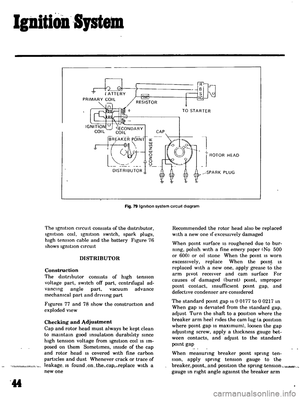
Fig
19
Igmtlon
system
Circuit
diagram
The
IgmtlOn
CirCUIt
conSIsts
of
the
distributor
IgmtIon
cOli
IgmtIon
sWitch
spark
plugs
hIgh
tensIOn
cable
and
the
battery
Figure
76
shows
IgmtlOn
CirCUIt
DISTRIBUTOR
Construction
The
dIstributor
consists
of
high
tension
voltage
part
SWitch
off
part
centrifugal
ad
vancing
angle
part
vacuum
advance
mechamcal
part
and
drlvmg
part
Figures
77
and
78
show
the
constructIOn
and
exploded
view
Checking
and
Adjustment
Cap
and
rotor
head
must
always
be
kept
clean
to
maintain
good
insulation
durability
since
high
tensIOn
voltage
from
IgmtIon
cOil
IS
Im
posed
on
them
SometImes
inside
of
the
cap
and
rotor
head
IS
covered
wIth
fine
carbon
partIcles
and
dust
Whenever
crack
or
trace
of
leakage
IS
found
on
the
cap
replace
w1th
a
new
one
44
Recommended
the
rotor
head
also
be
replaced
wIth
a
new
one
If
excessively
damaged
When
pomt
surface
IS
roughened
due
to
bur
nlng
polish
with
a
fine
emery
paper
No
500
or
600
or
011
stone
When
the
point
IS
worn
excessively
replace
When
the
POIn
IS
replaced
with
a
new
one
apply
grease
to
the
arm
pivot
receiver
and
cam
surface
For
causes
of
damaged
burnt
point
Improper
pomt
contact
msufficlent
point
gap
and
defective
condenser
are
conSidered
The
standard
pomt
gap
IS
0
0177
to
0
0217
m
When
gap
IS
devIated
from
the
standard
gap
adjust
Turn
the
shaft
to
a
posItIon
where
the
breaker
arm
heel
rides
the
cam
lug
a
posItIon
where
pomt
gap
IS
maxImum
loosen
the
gap
adjusting
screw
apply
a
thIckness
gauge
bet
ween
contacts
and
adjust
to
the
standard
pomt
gap
When
measurmg
breaker
pomt
spring
ten
SIOn
apply
sprmg
tensIOn
gauge
to
the
breaker
pomt
and
posItIon
the
sprmg
tenslOn
gauge
m
right
angle
agamst
the
breaker
arm
Page 44 of 136

Ignition
Sptem
The
standard
breaker
pOint
spring
tensIOn
IS
1
1
to
1
4
lb
Replace
If
devIated
Performance
of
condenser
IS
affected
by
Im
proper
setting
contaminatIOn
and
reductIOn
of
In
ulatlOn
resIstance
Thus
pellOdlcal
checking
I
I
eqlJ
lred
to
maintain
the
outlet
of
lead
wire
clean
and
to
prevent
et
screw
from
loosening
Checking
the
condenser
capacIty
IS
checked
USing
a
capacity
meter
It
may
be
also
checked
condenser
Isolate
resl
tance
USing
a
tester
by
adjusting
ItS
I
ange
to
measure
large
I
eSlstance
value
When
the
condenser
IS
normal
the
tester
pOinter
SWings
1m
gely
and
rapIdly
and
moves
gradually
back
to
the
Infimte
SIde
When
the
pOinter
does
not
stay
stili
or
It
points
Zero
In
reSIstance
replacement
IS
necessary
Fig
82
AdJusllng
POint
gap
Fig
83
Measunng
breaker
POint
spnng
tension
g
SPARK
PLUGS
Description
The
spark
plugs
are
of
the
re
lster
type
haVing
0
551
In
threads
and
0031
to
0035
11i
gap
Note
All
spark
plugs
installed
on
an
engme
must
be
of
the
same
brand
and
number
of
heat
range
Inspection
Remove
spark
plug
wIre
by
pulhng
on
boot
not
on
WIre
Itself
Remove
spark
plugs
Check
electrodes
and
Inner
and
outer
por
celams
of
plugs
noting
the
type
of
depOSits
and
the
degree
of
electrode
erO
lOn
Refer
to
Figure
85
Normal
Brown
to
gl
aYlsh
tan
depoSits
and
shght
electrode
wear
indIcate
correct
spark
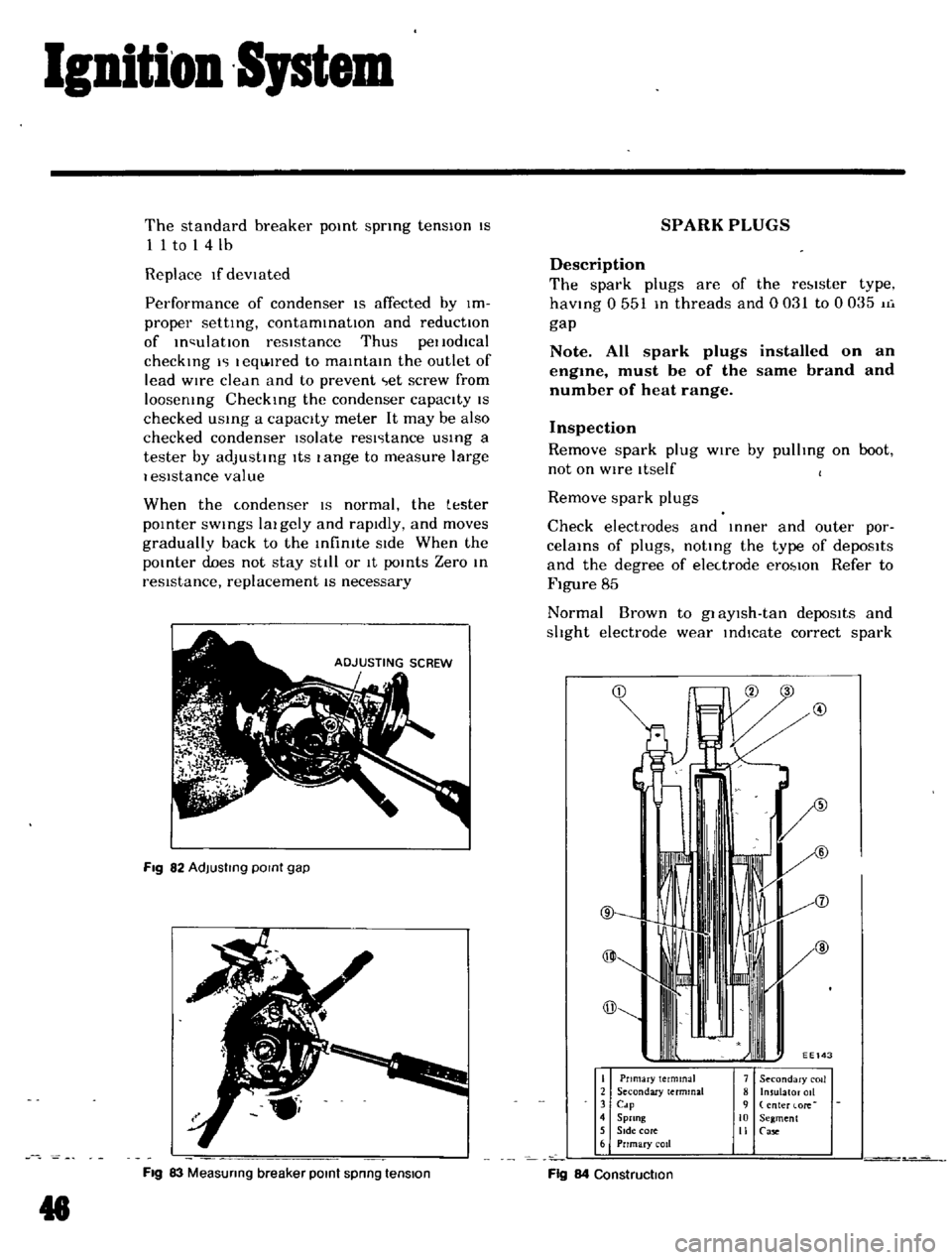
@
I
Pnmary
terminal
2
Secondary
terminal
3
Cdp
4
Sprang
5
SIde
core
6
Prrmary
coil
7
Secondary
COIl
8
Insulator
011
9
enter
lore
10
Segment
II
Case
Fig
84
Construction