1969 DATSUN B110 height adjustment
[x] Cancel search: height adjustmentPage 5 of 136
labl8
of
Contents
Jets
60
FRONT
SUSPENSION
TlOuble
Shooting
60
f
DESCRIPTION
RECOMMENDATIONS
TROUBLE
SHOOTING
I
85
COOLING
SYSTEM
DESCRIPTION
64
STEERING
WATER
PUMP
64
Hemoval
65
DESCRIPTION
90
InstallatIOn
65
RECOMMENDATIONS
90
THERMOSTAT
65
TROUBLE
SHOOTING
91
Removal
65
InspectIOn
65
REAR
DRIVE
Installation
65
RADIATOR
66
SUSPENSION
Hemovdl
66
InspectIOn
66
REAR
AXLE
94
InstallatIOn
66
DIFFERENTIAL
94
REAR
SUSPENSION
95
REAR
SHOCK
ABSORBER
96
Replacement
96
BRAKES
InspectIOn
97
RECOMMENDATIONS
97
FRONT
DISC
BRAKE
68
BRAKE
PAD
68
Replacement
68
CLUTCH
InspectIOn
68
ReinstallatIOn
68
DESCRIPTION
CALIPER
70
CLUTCH
PEDAL
Removal
70
Removal
Disassembly
71
InspectIOn
InspectIOn
Repmr
71
ReinstallatIOn
Reassembly
72
Adjustment
ReinstallatIOn
74
CLUTCH
MASTER
CYLINDER
REAR
BRAKE
74
Removal
Hemoval
Dlsdssembly
74
DIsassembly
InspectIOn
75
InspectIOn
Reassembly
ReinstallatIOn
75
Reassembly
HAND
BRAKE
75
RemstallatlOn
Removal
75
BLEEDING
CLUTCH
SYSTEM
InspectIOn
76
RemstallatlOn
77
ADJUSTMENT
78
TRANSMISSION
Front
DI
c
Brake
78
Rear
Brake
78
4
SPEED
TRANSMISSION
Brake
Pedal
HeIght
78
3
SPEED
TRANSMISSION
Hand
Brake
79
TROUBLE
SHOOTING
BLEEPIN
HYD
AULIC
SYs
r
M
79
i
UIQM
ATJ
C
TRANSMJSSIQ
TROUBLE
SHOOTING
80
RECOMMENDATIONS
2
Page 28 of 136
Bagine
Fig
55
ApplYing
adhesive
L
FIg
56
Flywheel
installation
c
0
FIg
57
Piston
and
connecting
rod
assembly
installation
281
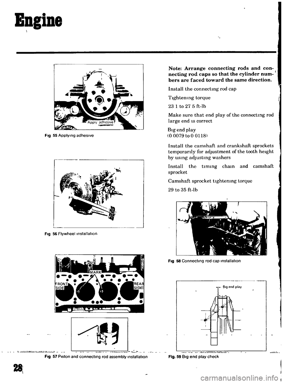
Note
Arrange
connecting
rods
and
con
necting
rod
caps
so
that
the
cylinder
num
bers
are
faced
toward
the
same
direction
Install
the
connectmg
rod
cap
Tlghtenmg
torque
23
1
to
27
5
ft
lb
Make
sure
that
end
play
of
the
connectmg
rod
large
end
IS
correct
Big
end
play
00079
to
0
0118
Install
the
camshaft
and
crankshaft
sprockets
temporarily
for
adjustment
of
the
tooth
height
by
usmg
adJustmg
washers
Install
the
tlmmg
cham
and
camshaft
sprocket
Camshaft
sprocket
tlghtemng
torque
29
to
35
ft
lb
FIg
58
Connecting
rod
cap
installation
Fig
59
Big
end
play
check
Page 73 of 136
Brakes
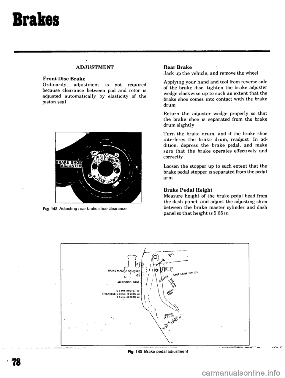
ADJUSTMENT
Front
Disc
Brake
Ordinarily
adJu
tment
IS
not
requIred
because
clearance
between
pad
and
rotor
IS
adjusted
automattcally
by
elasttclty
of
the
pIston
seal
I
iJ
1
el
i
C
1
FIg
142
AdJustmg
rear
brake
shoe
clearance
F
J
I
1
I
r
BRAKE
MASTER
CYLINDER
I
tI
Rear
Brake
Jack
up
the
vehicle
and
remove
the
wheel
ApplYing
your
hand
and
tool
from
reverse
side
of
the
brake
diSC
ttghten
the
brake
adjuster
wedge
clockWise
up
to
such
an
extent
that
the
brake
shoe
comes
Into
contact
With
the
brake
drum
Return
the
adjuster
wedge
properly
so
that
the
brake
shoe
IS
separated
from
the
brake
drum
slIghtly
Turn
the
brake
drum
and
If
the
brake
shoe
Interferes
the
brake
drum
readjust
In
ad
dition
depress
the
brake
pedal
and
make
sure
that
the
brake
operates
effecttvely
and
correctly
Loosen
the
stopper
up
to
such
extent
that
the
brake
pedal
stopper
IS
separated
from
the
pedal
arm
Brake
Pedal
Height
Measure
height
of
the
brake
pedal
head
from
the
dash
panel
and
adjust
the
adjusting
shim
between
the
brake
master
cylInder
and
dash
panel
so
that
height
IS
5
65
In
05mmlOQ197
nl
THICKNESS
0
8
mm
10
0315
0
16mm
100630
n
11
r
l00
Fig
143
Brake
pedal
adjustment
78
Page 74 of 136
Brakes
Adjusting
shIm
thickness
for
selectIOn
o
0197
In
00315
In
o
0630
In
Note
When
adjusting
be
sure
to
use
ad
Jusbng
sh1ms
having
same
th1ckness
for
upper
and
lower
brake
master
cylinder
IOstallahon
bolts
Upon
completIOn
of
adjusting
shIm
adjust
ment
tighten
the
stopper
down
to
such
an
ex
tent
that
heIght
of
the
pedal
head
IS
5
57
pO
0787
In
and
tighten
the
lock
nut
becurely
Free
travel
of
the
brake
pedal
IS
0
197
to
0591
tn
and
the
stroke
IS
4
72
In
Hand
Brake
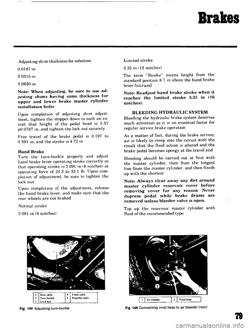
Turn
the
turn
buckle
properly
and
adjust
hand
brake
lever
operatmg
stroke
correctly
so
that
operatmg
stroke
IS
3
091
m
16
notches
at
operatIng
force
of
243
to
331
Ib
Upon
com
pletIOn
of
adjustment
be
sure
to
tIghten
the
lock
nut
Upon
completIOn
of
the
adjustment
release
the
hand
brake
lever
and
make
sure
that
the
rear
wheels
are
not
braked
Normal
btroke
3091
In
6
notches
Fig
144
AdJusting
turn
buckle
LImIted
stroke
535
tn
10
notches
The
term
Stroke
means
heIght
from
the
standard
posItIon
8
7
In
above
the
hand
brake
lever
fulcrum
Note
Readjust
hand
brake
stroke
when
it
reaches
the
hmited
stroke
5
35
in
10
notches
BLEEDING
HYDRAULIC
SYSTEM
BleedIng
the
hydrauhc
brake
system
deserves
much
attentIOn
as
It
IS
an
e
senttal
factor
for
regular
servICe
brake
operatIon
As
a
matter
of
fact
durmg
the
brake
serVice
air
IS
lIkely
to
creep
Into
the
CirCUIt
WIth
the
result
that
the
flUId
actIon
IS
altered
and
the
brake
pedal
becomes
spongy
at
the
travel
end
Bleedmg
should
be
carned
out
at
first
WIth
the
master
cylmder
then
from
the
longest
lIne
from
the
master
cylmder
and
then
fimsh
up
With
the
shortest
Note
Always
clear
away
any
dirt
around
master
cylinder
reservoir
cover
before
removing
cover
for
any
reason
Never
depress
pedal
while
brake
drums
are
removed
unless
bleeder
valve
IS
open
Top
up
the
reservOIr
master
cyltnder
With
flUId
of
the
recommended
type
Fig
145
Connecting
Vinyl
hose
to
air
bleeder
rear
79
Page 80 of 136
Pront
Suspension
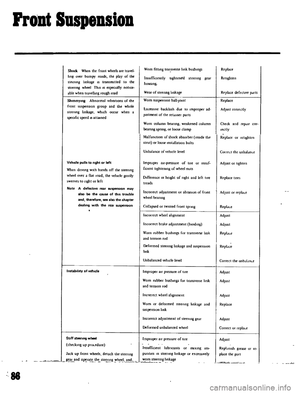
Shock
When
the
fronl
wheels
are
travel
Img
over
bumpy
roads
the
play
of
the
steenng
linkage
IS
transnutted
to
the
steering
wheel
This
IS
especially
notice
able
when
travellmg
rough
road
Shlmmymg
Abnormal
VIbratIOns
of
the
front
suspensIOn
group
and
lhe
whole
sleenng
hnkage
which
occur
when
a
specific
speed
IS
attamed
VehIcle
pulls
to
right
or
left
Vhen
driVing
With
hands
off
the
steering
wheel
over
a
flat
road
the
vehicle
gently
swerves
to
nght
or
lefl
Note
A
defective
rear
suspenSion
may
also
be
the
cause
of
tillS
trouble
and
therefore
see
also
the
chapter
dealing
With
the
rear
suspenSion
InstabilIty
of
vehIcle
Stoff
steering
wheel
checking
up
procedure
Jack
up
fronl
wheels
detach
the
steenng
g
nd
o
ra
h
ste
g
h
J
andk
88
Worn
fittmg
transverse
hnk
bushmgs
Insufficiently
tlghten
d
steenng
gear
housmg
Wear
of
steenng
hnkage
Worn
suspensIOn
ball
Jomt
E
xcesslve
backlash
due
to
improper
ad
Justment
of
the
ret
uner
parts
Worn
column
beanng
weakened
column
beanng
spnng
or
loose
clamp
MalfunctIOn
of
shock
absorber
inSIde
the
strut
or
loose
mstdllatJon
bolts
Unbalance
ofvehtcle
level
Improper
au
pressure
of
tire
or
msuf
ficlent
hghtenmg
of
wheel
nuts
Difference
In
height
of
nght
and
left
lIre
treads
Incorrect
adjustment
or
abraSIOn
of
front
wheel
beanng
Collapsed
or
tWisted
front
sprmg
Incorrect
wheel
alIgnment
Incorrect
brake
adjustment
bmdmg
Worn
rubber
bushmgs
for
transverse
link
and
tensIOn
rod
Deformed
steering
linkage
and
suspensIOn
lInk
Unbalanced
vehicle
level
Improper
au
pressure
of
tire
Worn
rubber
bushmgs
for
tmnsverse
Imk
and
tensIOn
rod
Incorrect
wheel
alignment
Worn
or
deformed
steenng
hnkage
and
suspensIOn
link
Incorrect
adjustment
of
steenng
gear
Deformed
unbalanced
wheel
Improper
au
pressure
of
lire
InsuffiCient
lubricants
or
nuxmg
Im
pun
ties
m
sleenng
linkage
or
exceSSively
o
steenng
Imkage
Replace
Rellghten
Replace
defective
p
uts
Replace
Adjust
correctly
Check
and
repdlT
cor
rectly
Replace
or
relighlen
Correl
t
the
unbaldnl
e
Adjust
or
tighten
Replace
tlTes
Adjust
or
replal
c
Repldcc
Adjust
Adlusl
Repl
n
e
Repldc
e
Correcl
the
unbdJdlKe
Adjust
AdlU
t
Adjust
Replace
AdJusl
Correcl
or
replaf
e
Adlust
Repl
msh
grease
or
re
place
the
pa
rt
Page 87 of 136
lear
Drive
Suspension
I
A
le
holft
2
SPdlU
3
Whl
c1
beanng
4
Whcd
be
mng
I
ollar
5
Oll
al
b
Hcanng
adjust
hlOl
7
Axle
a
C
8
BrJ
ke
drum
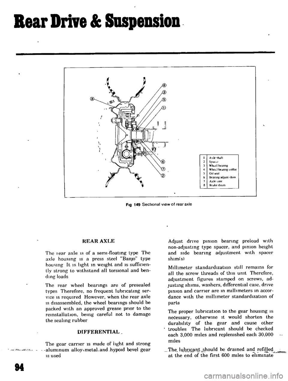
FIg
149
Sectional
vIew
of
rear
axle
REAR
AXLE
The
I
ear
axle
19
of
a
sem1
f10atIng
type
The
axle
hOUSIng
IS
a
press
steel
BanjO
type
hou
Ing
It
IS
light
In
weight
and
IS
sufficlen
tly
strong
to
wIthstand
all
torsIOnal
and
ben
ding
loads
The
rear
wheel
bearIngs
are
of
presealed
types
Therefore
no
frequent
lubncatIng
ser
vice
IS
reqUIred
However
when
the
rear
axle
IS
dIsassembled
the
wheel
bearings
should
be
packed
with
an
lpproved
grease
pnor
to
the
reInstallatIOn
beIng
careful
not
to
damage
the
sealing
rubber
DIFFERENTIAL
The
gear
carner
IS
made
of
light
and
strong
alumInum
alloy
metaLand
hYPOld
bevel
gear
IS
used
M
Adjust
dnve
pInIOn
bearIng
preload
wIth
non
adjustIng
type
spacer
and
pInion
height
and
Side
bearIng
adjustment
wIth
spacer
shlm
s
MIllimeter
standardIzatIOn
stili
remaInS
for
all
the
screw
threads
of
thIS
Unit
Therefore
adjustment
figures
stamped
on
screws
ad
JustIng
shIms
washers
dIfferentIal
case
dnve
pInIOn
and
carner
are
In
millimeters
In
accor
dance
with
the
millImeter
standardIzatIOn
of
parts
The
proper
lubncatlOn
to
the
gear
hOUSIng
IS
neCessary
otherWIse
It
would
shorten
the
durability
of
the
gear
and
cause
other
troubles
The
lubncant
should
be
checked
each
3
000
miles
and
replenished
each
30
000
miles
The
luJ
ncan
ks
hould
be
draIned
and
refilled
at
the
end
of
the
first
600
miles
to
eltm1l1ate
Page 92 of 136
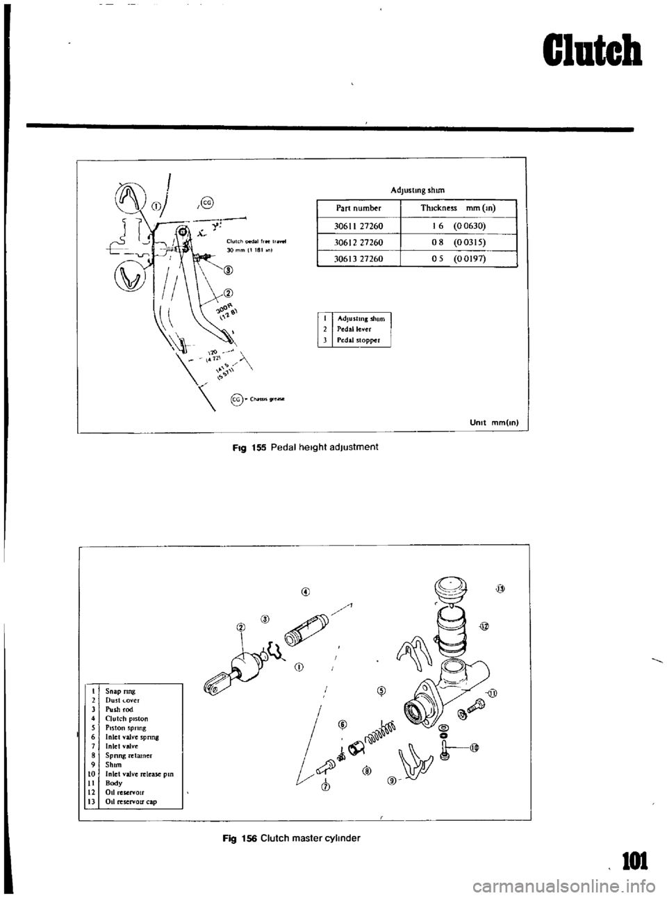
Snap
ring
Dust
over
Push
rod
Clutch
piston
Piston
Spring
Inlel
valve
S
Inlet
valve
pnng
Spnng
retamer
Shun
Inlet
valve
Body
release
pm
011
reservoir
011
reservou
cap
Part
number
Adlustmg
shun
ThIckness
mm
m
00630
00315
05
00197
Clutch
pedallrte
aY
tl
30
mm
1181
n
@
Ch
nl
lSgre
Fig
155
P
edal
height
adjustment
l
@
1
f
I
vy
J
@
W
Il
@
Ji
0
t
@
o
@
1
Fig
156
Clutch
master
cylinder
Clutch
101
Page 93 of 136
Clutch
Pedal
lever
bush
Fulcrum
pedal
pIn
etc
Remstallation
Reinstall
the
clutch
pedal
In
reverse
sequence
of
removal
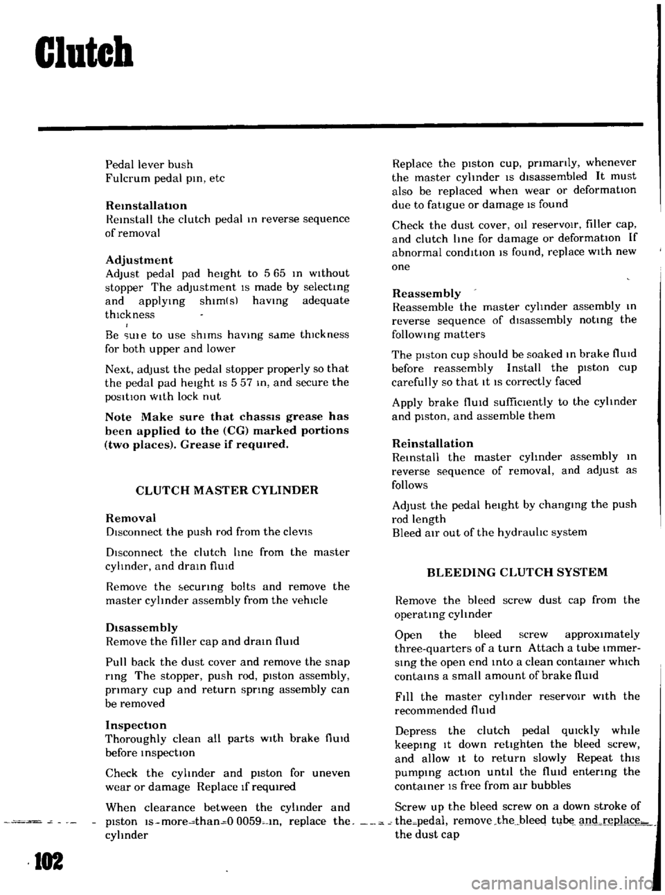
Adjustment
Adjust
pedal
pad
heIght
to
565
In
Without
stopper
The
adjustment
IS
made
by
selectmg
and
applYIng
shlm
s
haVing
adequate
thIckness
Be
Ule
to
use
shIms
haVIng
same
thIckness
for
both
upper
and
lower
Next
adjust
the
pedal
stopper
properly
so
that
the
pedal
pad
height
IS
557
In
and
secure
the
pOSitIOn
WIth
lock
nut
Note
Make
sure
that
chaSSIS
grease
has
been
applied
to
the
CG
marked
portions
two
places
Grease
if
reqUired
CLUTCH
MASTER
CYLINDER
Removal
DIsconnect
the
push
rod
from
the
cleVIS
DIsconnect
the
clutch
lIne
from
the
master
cylinder
and
draIn
flUid
Remove
the
ecunng
bolts
and
remove
the
master
cyhnder
assembly
from
the
vehIcle
DIsassembly
Remove
the
filler
cap
and
draIn
flUId
Pull
back
the
dust
cover
and
remove
the
snap
rIng
The
stopper
push
rod
pIston
assembly
pnmary
cup
and
return
sptlng
assembly
can
be
removed
Inspection
Thoroughly
clean
all
parts
With
brake
flUId
before
InspectIOn
Check
the
cyhnder
and
piston
for
uneven
wear
or
damage
Replace
If
required
When
clearance
between
the
cylinder
and
pIston
IS
more
than
O
0059
In
replace
the
cyhnder
102
Replace
the
pIston
cup
pnmanly
whenever
the
master
cyhnder
IS
dIsassembled
It
must
also
be
replaced
when
wear
or
deformatIOn
due
to
fatIgue
or
damage
IS
found
Check
the
dust
cover
OIl
reservOIr
filler
cap
and
clutch
lIne
for
damage
or
deformatIOn
If
abnormal
condItIOn
IS
found
replace
With
new
one
Reassembly
Reassemble
the
master
cylInder
assembly
In
reverse
sequence
of
dIsassembly
notIng
the
follOWIng
matters
The
pIston
cup
should
be
soaked
In
brake
flUId
before
reassembly
Install
the
pIston
cup
carefully
so
that
It
IS
correctly
faced
Apply
brake
flUId
suffiCIently
to
the
cyhnder
and
pIston
and
assemble
them
Reinstallation
ReInstall
the
master
cyhnder
assembly
In
reverse
sequence
of
removal
and
adjust
as
follows
Adjust
the
pedal
heIght
by
changmg
the
push
rod
length
Bleed
air
out
of
the
hydrauhc
system
BLEEDING
CLUTCH
SYSTEM
Remove
the
bleed
screw
dust
cap
from
the
operatIng
cyhnder
Open
the
bleed
screw
approximately
three
quarters
of
a
turn
Attach
a
tube
Immer
SIng
the
open
end
mto
a
clean
contaIner
which
contaInS
a
small
amount
of
brake
flUId
Fill
the
master
cyhnder
reservOIr
With
the
recommended
flUId
Depress
the
clutch
pedal
qUIckly
while
keepIng
It
down
retighten
the
bleed
screw
and
allow
It
to
return
slowly
Repeat
thiS
pumpIng
actIOn
unttl
the
flUId
entenng
the
contaIner
IS
free
from
air
bubbles
Screw
up
the
bleed
screw
on
a
down
stroke
of
the
pedal
remove
the
bleec
t1
1
nd
rel1lace
the
dust
cap