1969 DATSUN B110 water pump
[x] Cancel search: water pumpPage 5 of 136
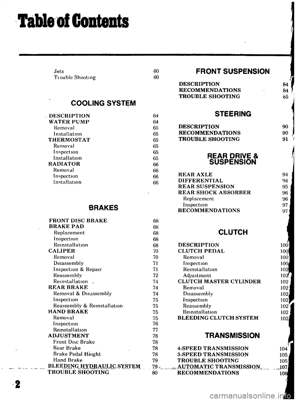
labl8
of
Contents
Jets
60
FRONT
SUSPENSION
TlOuble
Shooting
60
f
DESCRIPTION
RECOMMENDATIONS
TROUBLE
SHOOTING
I
85
COOLING
SYSTEM
DESCRIPTION
64
STEERING
WATER
PUMP
64
Hemoval
65
DESCRIPTION
90
InstallatIOn
65
RECOMMENDATIONS
90
THERMOSTAT
65
TROUBLE
SHOOTING
91
Removal
65
InspectIOn
65
REAR
DRIVE
Installation
65
RADIATOR
66
SUSPENSION
Hemovdl
66
InspectIOn
66
REAR
AXLE
94
InstallatIOn
66
DIFFERENTIAL
94
REAR
SUSPENSION
95
REAR
SHOCK
ABSORBER
96
Replacement
96
BRAKES
InspectIOn
97
RECOMMENDATIONS
97
FRONT
DISC
BRAKE
68
BRAKE
PAD
68
Replacement
68
CLUTCH
InspectIOn
68
ReinstallatIOn
68
DESCRIPTION
CALIPER
70
CLUTCH
PEDAL
Removal
70
Removal
Disassembly
71
InspectIOn
InspectIOn
Repmr
71
ReinstallatIOn
Reassembly
72
Adjustment
ReinstallatIOn
74
CLUTCH
MASTER
CYLINDER
REAR
BRAKE
74
Removal
Hemoval
Dlsdssembly
74
DIsassembly
InspectIOn
75
InspectIOn
Reassembly
ReinstallatIOn
75
Reassembly
HAND
BRAKE
75
RemstallatlOn
Removal
75
BLEEDING
CLUTCH
SYSTEM
InspectIOn
76
RemstallatlOn
77
ADJUSTMENT
78
TRANSMISSION
Front
DI
c
Brake
78
Rear
Brake
78
4
SPEED
TRANSMISSION
Brake
Pedal
HeIght
78
3
SPEED
TRANSMISSION
Hand
Brake
79
TROUBLE
SHOOTING
BLEEPIN
HYD
AULIC
SYs
r
M
79
i
UIQM
ATJ
C
TRANSMJSSIQ
TROUBLE
SHOOTING
80
RECOMMENDATIONS
2
Page 15 of 136
Bngine
WIres
for
accelerator
and
choke
The
operatIOn
Will
be
carned
out
more
easily
by
removing
the
a1r
cleaner
Lift
up
the
engine
toward
the
front
INST
ALLA
TION
Install
the
engine
In
reverse
sequence
of
removal
Disconnecting
clutch
wire
on
nght
hand
dnve
model
On
left
hand
dnve
model
disconnect
hydraulIc
line
from
the
clutch
slave
cylInder
DIsconnect
the
clutch
WIre
at
the
JXlrtlOn
of
the
wIthdrawal
lever
Remove
the
exhaust
front
tube
Disconnect
the
the
cable
to
the
back
up
lamp
SWItch
D1sconnect
the
speedometer
cable
Remove
the
propeller
shaft
Remove
four
bolts
used
In
the
differential
carner
SIde
and
Withdraw
the
propeller
shaft
Remove
the
shift
lever
Model
With
remote
control
shIft
lever
Disconnect
the
remote
control
rod
at
the
JXlr
tlOn
of
transmiSSIOn
outer
lever
and
remove
the
remote
control
rod
Model
With
floor
Sh1ft
lever
Remove
the
boot
WIthdraw
the
lock
pin
and
remove
the
lever
The
operatIOn
IS
carned
out
In
the
passenger
compartment
Model
With
automatic
transmiSSIOn
Remove
pinS
from
both
ends
of
the
cross
shaft
and
remove
the
shIft
rod
Suspend
the
engine
With
wire
Remove
the
front
engine
mounting
installation
nuts
Remove
the
rear
engine
mounting
installation
nuts
When
removing
the
engine
mounting
in
stallation
nuts
be
sure
to
apply
a
Jack
beneath
the
transmiSSIOn
CLEANING
AND
INSPECTION
Clean
the
engine
thoroughly
before
disassem
bly
Before
cleaning
the
engine
remove
the
l
electncal
parts
and
plug
up
the
carburetor
air
horn
to
aVOid
intrusIOn
of
foreign
matter
The
engine
extenor
Check
the
covers
and
bolts
for
breakage
rust
damage
and
loss
CylInder
block
Check
thoroughly
the
water
Jacket
for
cracks
and
breakage
Clutch
hOUSing
Check
for
cracks
011
pan
Check
for
excessive
rust
DISASSEMBLY
Mount
engine
assembly
on
engine
stand
Remove
the
engine
mounting
bracket
R
H
Side
Install
the
engine
attachment
Mount
the
engine
on
the
stand
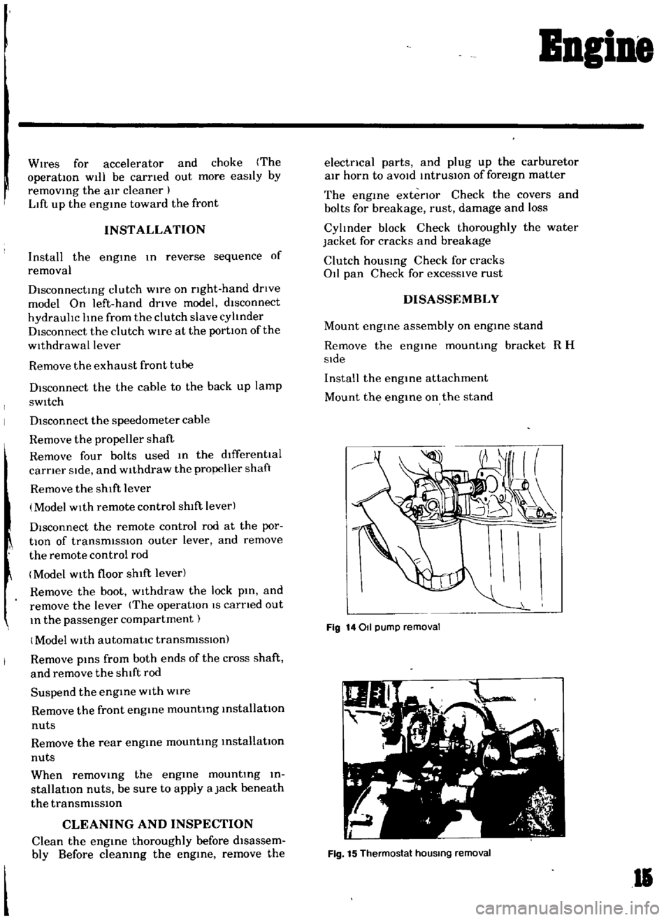
Fig
14011
pump
removal
Fig
15
Thermostat
hOUSing
removal
II
Page 16 of 136
Bngine
Remove
the
altel
nator
and
engine
mounting
bracket
L
H
slde
Remove
the
crankshaft
pulley
Remove
the
011
pump
together
With
the
011
filtel
Remove
the
high
tensIOn
cable
wIth
the
dlstnbutor
cap
on
Remove
the
spark
plugs
Remove
the
dlstllbutor
assembly
Remove
the
carburetor
Remove
the
rocker
cover
Remove
the
thermo
itat
houslllg
Remove
the
manifolds
Remove
the
water
pump
Remove
the
fuel
pump
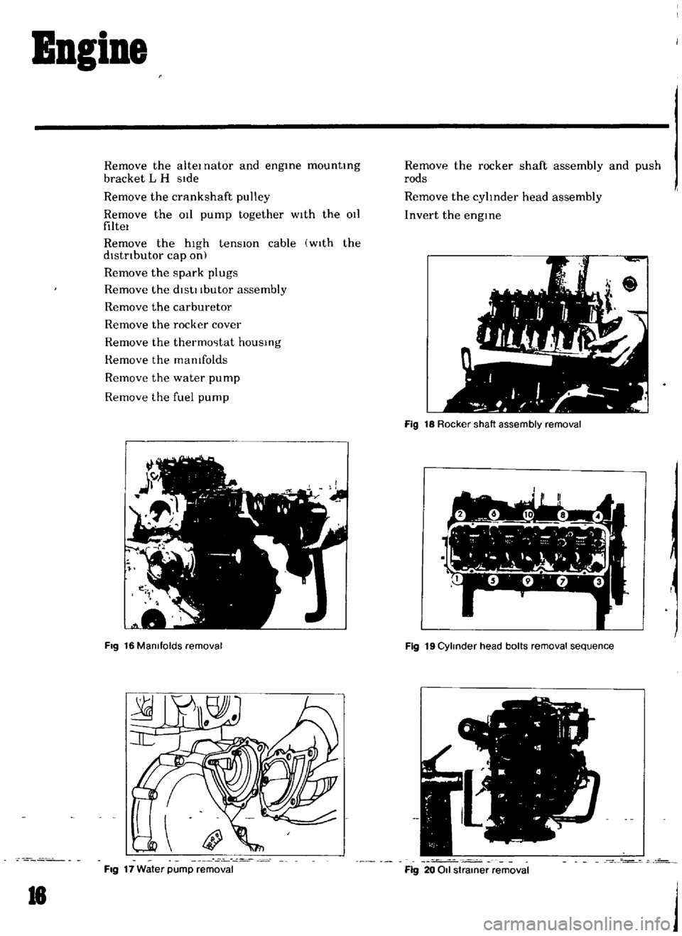
Fig
16
Manifolds
removal
Fig
17
Water
pump
removal
18
Remove
the
rocker
shaft
assembly
and
push
rods
Remove
the
cylInder
head
assembly
Invert
the
engine
Fig
18
Rocker
shaft
assembly
removal
7
1
l
I
h
Y
r
I
w
L
1
Fig
19
Cylinder
head
bolts
removal
sequence
o
Fig
20
011
strainer
removal
j
Page 56 of 136
Fuel
Sptem
In
removIng
Injector
weight
piston
return
sptlng
and
ball
care
should
be
exercIsed
to
prevent
them
from
beIng
scattered
and
lost
To
check
the
accelerator
pump
the
pump
cover
IS
removed
Be
careful
not
to
lose
the
return
spring
and
mlet
valve
bal
prOVided
at
the
lower
part
of
the
piston
dUring
dIsassembly
Removal
of
bl
metal
cover
IS
a
sImple
matter
of
removmg
three
set
screws
When
It
becomes
necessary
to
take
out
float
pull
shaft
from
float
Note
Under
no
C1rcumstances
should
bl
metaI
be
moved
with
excessive
force
Since
this
may
cause
a
permanent
set
In
b1
metal
making
starting
d1fficuIt
The
thlottle
chamber
can
be
detached
from
the
float
hamber
by
removmg
three
set
screws
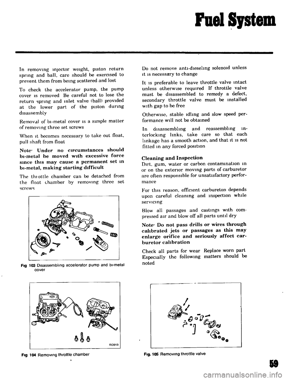
Fig
103
Disassembling
accelerator
pump
and
bl
metal
cover
1
EC013
Fig
104
RemOVing
throttle
chamber
Do
not
remove
antl
dlesehng
solenOId
unless
It
IS
necessary
to
change
It
IS
preferable
to
leave
throttle
valve
mtact
unless
otherWise
reqUIred
If
throttle
valve
must
be
dIsassembled
to
remedy
a
defect
secondary
throttle
valve
must
be
Installed
wIth
gap
to
be
free
OtherWise
stable
Idlmg
and
slow
speed
per
formance
Will
not
be
obtamed
In
dlsassembhng
and
reassembhng
in
terlockIng
hnks
take
care
so
that
each
lInkage
has
a
smooth
action
and
that
It
IS
not
fitted
m
any
forced
posltton
Cleaning
and
Inspection
Dirt
gum
water
or
carbon
contammatIon
m
or
on
the
exterior
movmg
parts
of
carburetor
are
often
responsible
for
unsattsfactory
perfor
mance
For
thiS
reason
effiCient
carbureton
depends
upon
careful
cleamng
and
InspectIOn
whtle
servlcmg
Blow
all
passages
and
castmgs
wIth
com
pressed
aIr
and
blow
off
all
parts
unttl
dry
Note
Do
not
pass
drills
or
wires
through
calibrated
jets
or
passages
as
this
may
enlarge
orifice
and
seriously
affect
car
buretor
calibration
Check
all
parts
for
wear
Replace
worn
part
EspeCially
the
followmg
matters
should
he
noted
I
1
Q
o
Fig
105
RemOVing
throttle
valve
18
Page 60 of 136
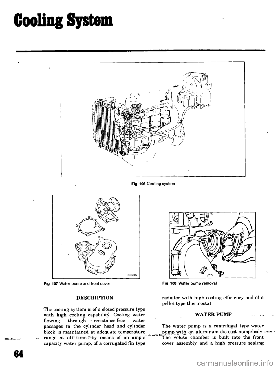
Cooling
Sptem
Fig
106
Coolmg
system
C0026
FIg
107
Water
pump
and
front
cover
FIg
1I1S
Water
pump
removal
DESCRIPTION
radiator
w1th
hIgh
coohng
efficiency
and
of
a
pellet
type
thermostat
The
coohng
system
IS
of
a
closed
pressure
type
With
hIgh
coolmg
capablhty
Coohng
water
WATER
PUMP
flowmg
through
resIstance
free
water
passages
m
the
cyhnder
head
and
cyhnder
The
water
pump
IS
a
centrifugal
type
water
block
IS
mamtamed
at
adequate
temperature
pum
WIth
an
alumlpum
d1e
cast
pump
body
range
at
allo
tlmes
by
means
of
an
ample
T
he
olute
chamber
IS
bUIlt
mto
the
front
capacIty
water
pump
of
a
corrugated
fin
type
cover
assembly
and
a
high
pressure
seahng
84
Page 61 of 136
GooliDI
Sptem
mechamsm
IS
adopted
to
prevent
the
water
leakage
and
nOIse
completely
Note
The
water
pump
must
not
be
disassembled
since
the
bearings
are
shrmkage
fitted
to
their
bores
If
any
part
of
water
pump
is
found
defective
replace
pump
assembly
Removal
Dram
coolmg
water
completely
Take
the
fan
belt
ofT
the
pulley
Remove
fan
and
pulley
Remove
the
water
pump
Installation
InstallatIOn
IS
the
reverse
of
removal
THERMOSTAT
A
pellet
type
thermostat
IS
used
m
the
water
outlet
passage
to
control
the
flow
of
coolant
provldmg
fast
engme
warm
up
and
regulatmg
coolant
temperature
A
wax
pellet
m
the
ther
mo
tat
expands
when
heated
and
contracts
when
cooled
The
pellet
IS
connected
through
a
piston
to
a
valve
and
when
the
pellet
IS
heated
pressure
IS
exerted
agamst
a
rubber
dIaphragm
and
the
valve
opens
As
the
pellet
IS
cooled
the
contractIOn
allows
the
sprmg
to
close
the
valve
Removal
Dram
coohng
water
Remove
radiator
hose
Remove
water
outlet
elbow
Then
take
out
the
thermostat
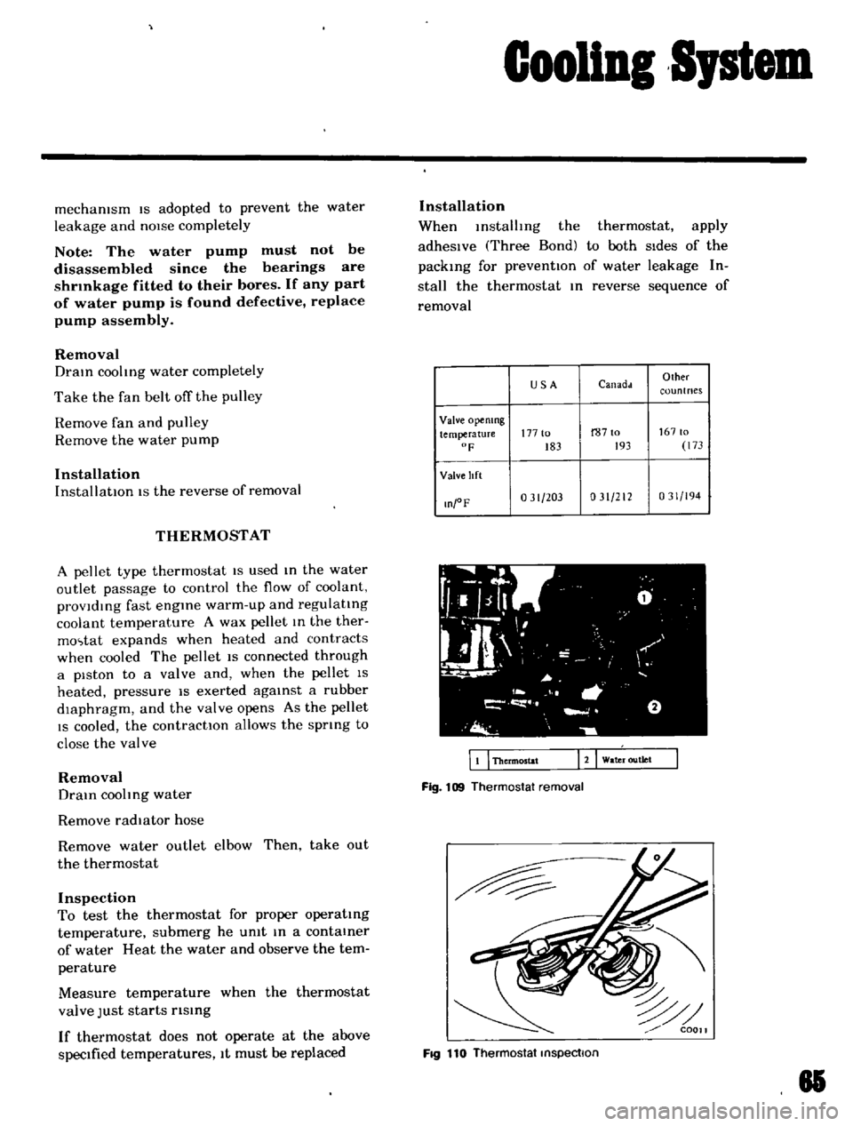
Inspection
To
test
the
thermostat
for
proper
operatmg
temperature
submerg
he
umt
m
a
contamer
of
water
Heat
the
water
and
observe
the
tem
perature
Measure
temperature
when
the
thermostat
valve
Just
starts
rlsmg
If
thermostat
does
not
operate
at
the
above
specIfied
temperatures
It
must
be
replaced
Installation
When
mstalhng
the
thermostat
apply
adheSIve
Three
Bond
to
both
SIdes
of
the
packmg
for
preventIOn
of
water
leakage
In
stall
the
thermostat
m
reverse
sequence
of
removal
USA
Canadd
Olher
coun
t
nes
Valve
opemng
temperature
177
to
r8710
16710
F
183
193
173
Valve
lIft
O
oF
031
203
031
212
031
194
WI
fL
g
0
I
l
1
L
JI
I
I
I
I
a
J
i
o
wa
r
outlet
EI
Thermostat
Fig
109
Thermostat
removal
FIQ
110
Thermostat
inspection
81