Page 27 of 136

Bogine
Note
Set
the
locate
plate
so
as
the
LOWER
mark
comes
to
the
engine
bot
tom
side
Set
the
maIn
bearIngR
on
theIr
posItIOns
on
the
cylinder
block
Notes
a
The
center
bearmg
No
3
bearmg
is
a
flanged
type
for
thrust
force
b
Two
lOner
bearmgs
No
2
and
No
4
are
of
the
same
type
c
The
front
bearmg
No
1
IS
the
same
type
as
the
rear
bearmg
No
5
d
All
bearings
except
for
No
I
bearing
are
interchangeable
between
upper
and
lower
bearings
Apply
engIne
OIl
to
the
mam
bearIng
surfaces
on
both
sIdes
of
the
cyltnder
block
and
cap
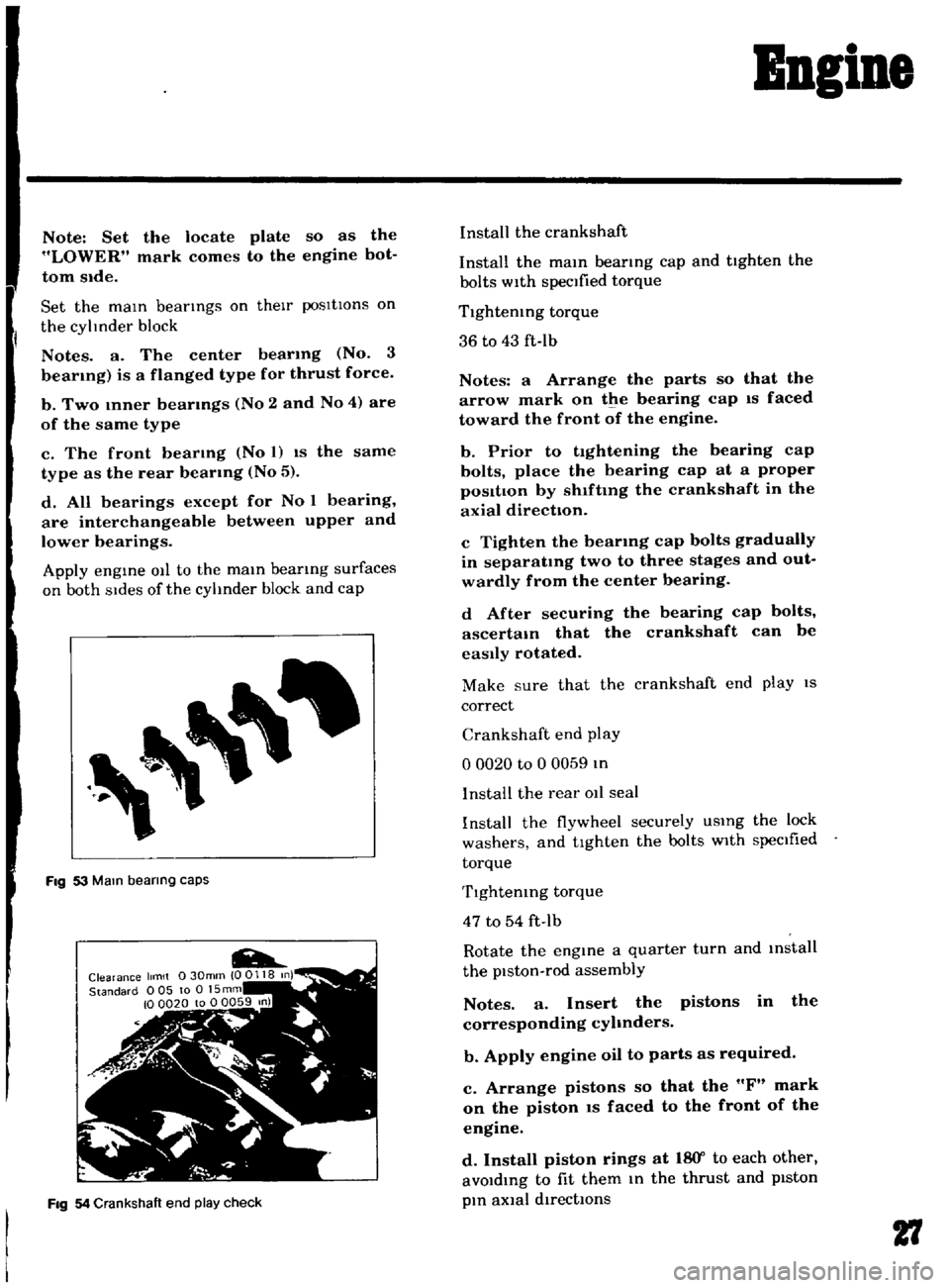
Fig
53
Mam
bearing
caps
Fig
54
Crankshaft
end
play
check
Install
the
crankshaft
Install
the
mam
bearmg
cap
and
tighten
the
bolts
with
specified
torque
Tlghtemng
torque
36
to
43
ft
Ib
Notes
a
Arrange
the
parts
so
that
the
arrow
mark
on
the
bearing
cap
IS
faced
toward
the
front
of
the
engine
b
Prior
to
tightening
the
bearing
cap
bolts
place
the
bearing
cap
at
a
proper
posItIon
by
shlftmg
the
crankshaft
in
the
axial
direction
c
Tighten
the
bearmg
cap
bolts
gradually
in
separatmg
two
to
three
stages
and
out
wardly
from
the
center
bearing
d
After
securing
the
bearing
cap
bolts
ascertam
that
the
crankshaft
can
be
easily
rotated
Make
sure
that
the
crankshaft
end
play
IS
correct
Crankshaft
end
play
o
0020
to
0
0059
In
I
nstalI
the
rear
011
seal
Install
the
flywheel
securely
USIng
the
lock
washers
and
tighten
the
bolts
with
specIfied
torque
Tlghtemng
torque
47
to
54
ft
Ib
Rotate
the
engine
a
quarter
turn
and
mstall
the
piston
rod
assembly
Notes
a
Insert
the
pistons
in
the
corresponding
cyhnders
b
Apply
engine
oil
to
parts
as
required
c
Arrange
pistons
so
that
the
F
mark
on
the
piston
IS
faced
to
the
front
of
the
engine
d
Install
piston
rings
at
18
Y
to
each
other
avoIdIng
to
fit
them
In
the
thrust
and
pIston
pIn
aXial
directIOns
27
Page 75 of 136

Brakes
Thoroughly
Wipe
the
bleeder
screw
and
from
any
mud
or
dust
present
so
that
the
outlet
hole
IS
free
from
foreign
matter
Attach
a
VInyl
hose
to
the
wheel
cyhnder
bleeder
screw
Dip
the
end
of
the
VInyl
hose
In
a
Jar
contaInIng
some
brake
flUId
Depress
the
brake
pedal
two
to
three
times
and
keep
the
pedal
fully
depressed
With
the
brake
pedal
fully
depressed
loosen
the
bleeder
screw
exhaust
air
and
rettghten
the
bleeder
screw
qUIckly
Return
the
brake
pedal
slowly
Repeat
the
operatIons
above
Air
WIll
no
longer
come
out
from
the
bleeder
screw
but
brake
flUId
comes
out
When
atr
stIll
eXists
In
brake
flUId
It
appears
whIte
due
to
aIr
bub
ble
Conduct
aIr
bleedIng
on
other
wheel
cyhnders
In
the
same
manner
Note
a
Check
the
reservoir
for
fluid
level
during
bleeding
operation
b
FlUid
withdrawn
in
the
operation
should
not
be
used
refilling
bleeding
again
for
c
When
the
master
cylinder
is
dIsassem
bled
or
replaced
conduct
air
bleeding
on
the
wheel
cylinder
which
is
located
most
near
the
master
cyhnder
d
Ordinarily
air
bleeding
is
performed
in
the
following
sequence
Rear
left
Rear
right
Front
left
Front
right
e
Do
not
return
the
brake
pedal
before
retightening
the
bleeder
screw
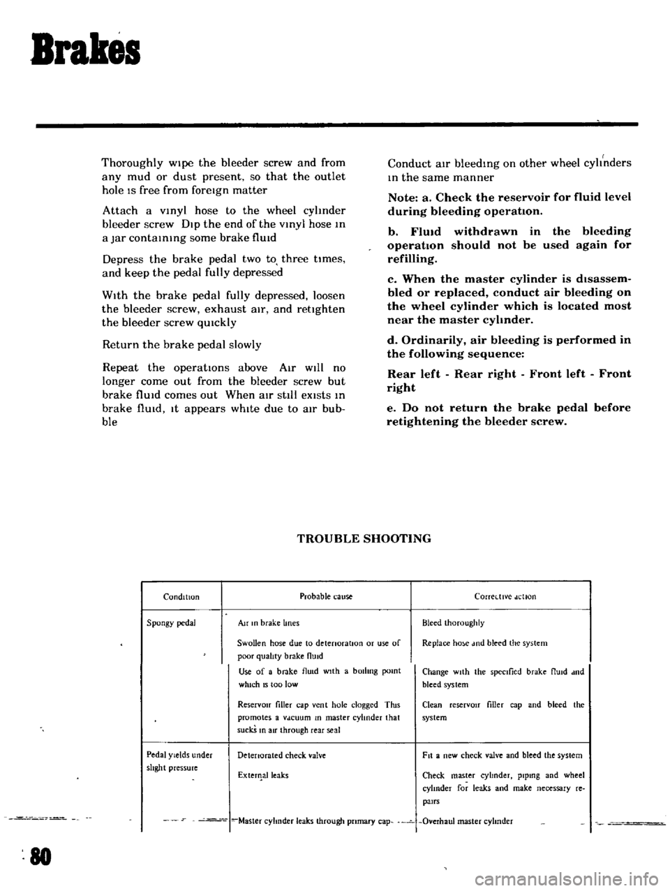
TROUBLE
SHOOTING
Condition
Probable
cause
Corretttve
dellon
Spongy
pedal
Au
In
brake
lines
Bleed
Ihoroughly
Swollen
hose
due
to
detenoratlOn
or
use
of
Replace
ho
e
md
bleed
the
system
poor
qualIty
brake
flUid
Use
of
a
brake
flu
d
wIth
a
bOilIng
pomt
Change
wIth
the
spectlied
brake
flUId
dnd
which
15
too
low
bleed
system
ReservOir
filler
cap
vent
hole
clogged
Tins
Clean
reserVOIr
filler
cap
and
bleed
the
promotes
a
Vdcuum
In
master
cylinder
that
system
suckS
In
air
through
rear
seal
Pedal
Yields
under
Detenorated
check
valve
Fit
a
new
check
valve
and
bleed
the
system
shght
pressure
ExterIlalleaks
Check
master
cyhnder
plpmg
and
wheel
cylInder
for
leaks
and
make
necessary
re
pairs
Master
cyhnder
leaks
through
pnmary
cap
Overhaul
master
cyhnder
80
Page 88 of 136

Bear
Drive
Suspension
A
correct
contact
pattern
means
that
It
beii
the
ange
of
2
3
to
3
4
from
the
tip
of
the
tooth
nder
no
load
Backlash
IS
010
to
015mm
00039
to
00059
n
Tlghtemng
torque
of
drlve
gear
bolt
60
to
70
kg
m
434
to
506
ft
Ibl
TIghten
by
tapping
bolt
head
with
a
0
lkg
1
4
lb
hammer
TIghtening
torque
of
dnvt
pmlon
nut
12
to
11
kg
m
86
8
to
1229
ft
lb
Plmon
be
nng
adjust
spacer
O
lve
plmon
adlustlng
washer
T
W
N
HxO
011
0
2
mml
T
T
Drive
gear
ad
ustlng
shims
Left
Ide
T1
jA
C
0
H
I
001
0200
E
lmml
Right
SIde
T2
B
D
HI
001
0
200
F
mml
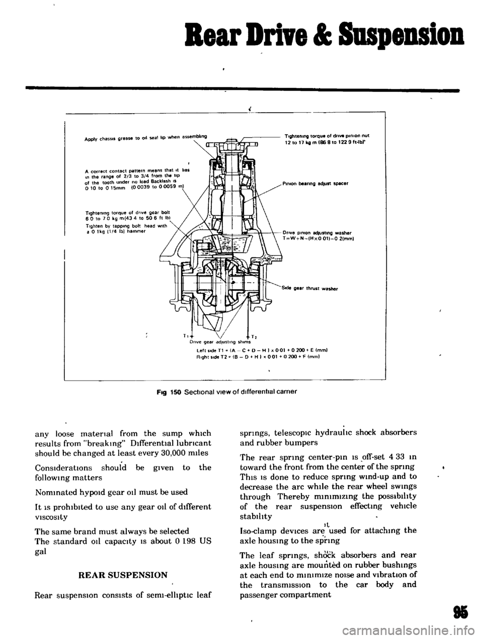
Fig
150
Sectional
view
of
dIfferentIal
carner
any
loose
matenal
from
the
sump
which
results
from
breaking
Dlfferentlallubncant
should
be
changed
at
least
every
30
000
m11es
ConsIderatIOns
should
be
given
to
the
follOWing
matters
Nommated
hYPOld
gear
011
must
be
used
It
IS
prohibited
to
use
any
gear
011
of
dIfferent
VISCOSity
The
same
brand
must
always
be
selected
The
standard
011
capacity
IS
about
0
198
US
gal
REAR
SUSPENSION
Rear
suspensIOn
consists
of
serm
elhptlc
leaf
springs
telescopIc
hydrauhc
shock
absorbers
and
rubber
bumpers
The
rear
sprmg
center
pm
1S
ofT
set
4
33
m
toward
the
front
from
the
center
of
the
sprmg
ThIS
IS
done
to
reduce
sprmg
wmd
up
and
to
decrease
the
arc
while
the
rear
wheel
sWings
through
Thereby
m1n1mlzmg
the
POSSibilIty
of
the
rear
suspensIOn
effecting
vehlCle
stablhty
It
Iso
damp
deVices
are
used
for
attachmg
the
axle
hOUSing
to
the
sprmg
The
leaf
sprmgs
shock
absorbers
and
rear
axle
housmg
are
mounted
on
rubber
bushings
at
each
end
to
minimIZe
nOIse
and
VibratIOn
of
the
transmiSSIon
to
the
car
body
and
passenger
compartment
85