1969 DATSUN B110 fuel type
[x] Cancel search: fuel typePage 13 of 136
aiDtenuce
TUDe
up
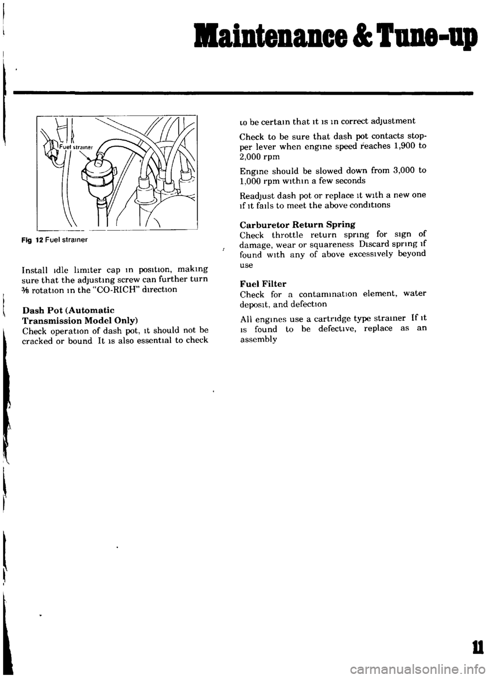
Fig
12
Fuel
strainer
Install
Idle
hmlter
cap
m
posItion
makmg
sure
that
the
adJustmg
screw
can
further
turn
rotatIOn
m
the
CO
RICH
d1rectlOn
Dash
Pot
Automatic
Transmission
Model
Only
Check
operation
of
dash
pot
It
should
not
be
cracked
or
bound
It
IS
also
essenttal
to
check
r
w
be
certam
that
It
IS
m
correct
adjustment
Check
to
be
sure
that
dash
pot
contacts
stop
per
lever
when
engme
speed
reaches
1
900
to
2
000
rpm
Engme
should
be
slowed
down
from
3
000
to
1
000
rpm
within
a
few
seconds
Readjust
dash
pot
or
replace
It
with
a
new
one
lflt
falls
to
meet
the
above
condItions
Carburetor
Return
Spring
Check
throttle
return
sprmg
for
sign
of
damage
wear
or
squareness
Discard
spring
If
found
wIth
any
of
above
excessIvely
beyond
use
Fuel
Filter
Check
for
a
contammatlOn
element
water
depoSIt
and
defection
All
engmes
use
a
cartridge
type
strainer
If
1t
IS
found
to
be
defective
replace
as
an
assembly
u
Page 45 of 136
Icnition
Sptem
Ovcrhc
Jtmg
Norm
Jl
i
r
rJ
I
ttr
I
i
V
Carbon
fould
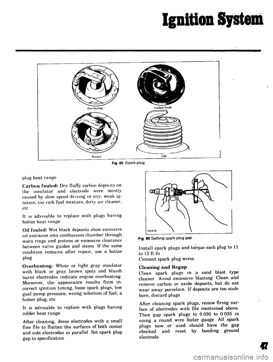
Fig
85
Spark
plug
Life
plug
heat
range
Carbon
fouled
Dry
fluffy
carbon
depo
lts
on
the
Insulator
and
electrode
were
mostly
caused
by
slow
speed
dnvlng
In
cIty
weak
Ig
nltlOn
too
nch
fuel
mixture
dirty
aIr
cleaner
etc
It
IS
advIsable
to
replace
WIth
plugs
havmg
hotter
heat
range
011
fouled
Wet
black
depoSits
show
excesSive
oIl
entrance
Into
combusllon
chamber
through
worn
rmgs
and
pIstons
or
excessIve
clearance
between
valve
gUIdes
and
stems
If
the
same
condition
remams
after
repair
use
a
hotter
plug
Overheatmg
WhIte
or
hght
gray
msulator
WIth
black
or
gray
brown
spots
and
blUIsh
burnt
electrodes
indIcate
engme
overheatIng
Moreover
th
e
appearance
results
from
in
correct
IgnitIon
tIming
loose
spark
plugs
low
guel
pump
pressure
wrong
selectIOn
of
fuel
a
hotter
plug
etc
It
IS
adVisable
to
replace
WIth
plugs
havmg
colder
heat
range
After
cleaning
dress
electrodes
With
a
small
fine
file
to
flatten
the
surfaces
of
both
center
and
Side
electrodes
In
parallel
Set
spark
plug
gap
to
specification
FIg
86
Settmg
spark
plug
gap
Install
spark
plugs
and
torque
each
plug
to
11
to
15
ft
Ib
Connect
spark
plug
wires
Cleaning
and
Regap
Clean
spark
plugs
In
a
sand
blast
type
cleaner
A
VOId
excessIve
blasting
Clean
and
remove
carbon
or
OXide
depoSits
but
do
not
wear
away
porcelain
If
depos1ts
are
too
stub
born
discard
plugs
After
cleaning
spark
plugs
renew
firing
sur
face
of
electrodes
With
file
mentioned
above
Then
gap
spark
plugs
to
0
030
to
0
035
In
uSing
a
round
wire
feeler
gauge
All
spark
plugs
new
or
used
should
have
the
gap
checked
and
reset
by
bending
ground
electrode
II
Page 47 of 136
ruel
Sptem
FUEL
FILTER
DESCRIPTION
The
fuel
filter
IS
of
a
cartndge
type
It
uses
paper
element
as
traIner
element
which
can
be
checked
for
condItIOn
from
outsIde
ThIS
filter
cannot
be
cleaned
Replace
the
filter
at
the
peclfied
servICe
Interval
01
If
It
becomes
clogged
or
I
estncted
REMOVAL
DIsconnect
Inlet
and
outlet
fuel
hnes
from
fuel
filter
and
remove
fuel
filter
if
EF005
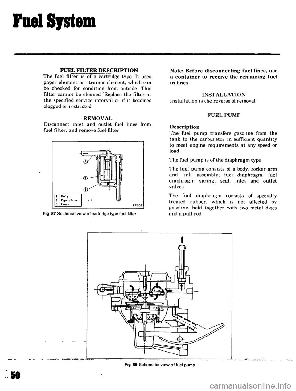
Fig
87
Sectional
view
of
cartridge
type
fuel
filter
Note
Before
disconnecting
fuel
lines
use
a
container
to
receive
the
remaining
fuel
In
lines
INSTALLATION
InstallatIOn
IS
the
reverse
of
removal
FUEL
PUMP
Description
The
fuel
pump
transfers
gasoline
from
the
tank
to
the
carburetor
In
suffiCient
quantity
to
meet
engine
requIrements
at
any
speed
or
load
The
fuel
pump
IS
of
the
diaphragm
type
The
fuel
pump
conSIsts
of
a
body
rocker
arm
and
link
assembly
fuel
diaphragm
fuel
diaphragm
spnng
seal
Inlet
and
outlet
valves
The
fuel
diaphragm
consists
of
specially
treated
rubber
whIch
IS
not
affected
by
gasohne
held
together
WIth
two
metal
diSCS
and
a
pull
rod
t
Fig
88
SchematiC
view
of
fuel
pump
R
0
Page 49 of 136
Fuel
Sptem
Capacity
Test
The
capaclty
test
IS
used
only
when
the
statIc
plessure
IS
wlthm
specIficatIOns
The
capacity
test
IS
conducted
as
follows
Disconnect
the
fuel
p1pe
at
the
carburetor
Place
a
bUltable
contamer
at
the
end
of
the
pIpe
Start
the
engme
and
run
at
1
000
rpm
The
pump
should
delIver
1
US
pt
of
fuel
In
one
mmute
or
less
If
no
gasolme
or
only
a
lIttle
flows
flOm
open
end
of
pIpe
the
fuel
pIpe
IS
clogged
or
the
pump
I
malfunctlOntng
Before
removing
the
pump
remove
the
gas
tank
cap
dIsconnect
both
Inlet
dnd
outlet
pIpes
and
blow
through
them
wIth
an
aIr
hose
to
make
sure
that
they
are
clear
Thl
wIll
elImmate
pOSSible
clogged
gas
tramer
In
the
fuel
tank
Reconnect
the
pIpes
to
the
pump
and
rete
t
flow
Removal
and
DisassenbIy
Remove
the
fuel
pump
assembly
by
un
screwmg
two
mounting
nuts
and
dIsassemble
In
the
follOWing
order
Separate
the
upper
body
and
the
lower
body
by
unscrewmg
the
body
set
screws
Take
off
the
cap
and
the
cap
gasket
by
I
emOVIng
the
cap
screw
Unscrew
the
elbow
and
the
connector
Take
off
the
valve
retainer
by
unscrewmg
two
valve
retamer
screws
Two
valves
are
eaSIly
removed
To
remove
the
diaphragm
diaphragm
sprmg
lower
body
seal
washer
and
lower
body
seal
from
the
lower
body
press
down
the
dIaphragm
counter
to
the
force
of
the
dIaphragm
spring
and
while
dOIng
thIS
cant
the
dIaphragm
so
that
the
rectangular
part
m
the
lower
end
of
the
pull
rod
IS
unhooked
from
the
rocker
arm
lInk
Inspection
Check
the
upper
and
lower
bodIes
for
cracks
2
Check
the
valve
assembly
for
wear
of
the
valve
and
valve
sprmg
Blow
the
valve
assem
bly
by
breath
to
examme
ItS
functIOn
Check
the
dIaphragm
for
small
holes
cral
ks
and
wear
Check
the
rocker
dl
m
for
wear
at
the
portIOn
In
contact
With
the
camshaft
Check
the
rocker
arm
pin
for
wear
since
a
worn
pm
may
cause
011
leakage
Check
all
other
components
for
any
abnor
mahtIes
and
replace
With
new
parts
as
requIred
Assembly
Assembly
IS
done
In
reverse
order
of
disassem
bly
For
reassembly
and
remstallatlOn
the
followmg
matters
should
be
noted
Use
new
gasket
Lubricate
the
rocker
arm
link
rocker
arm
pm
and
lever
pm
before
mstallatlOlI
To
test
the
functIOn
poSItIOn
the
fuel
pump
assembly
about
33ft
above
fuel
level
WIth
a
pipe
connecting
the
fuel
pump
and
the
fuel
filter
and
operate
the
rocker
arm
by
hand
If
fuel
IS
drawn
up
soon
after
the
rocker
arm
IS
released
the
functIOn
of
the
pump
IS
satIsfactory
CARBURETOR
Description
The
carburetors
are
of
a
downdraft
type
whIch
IS
deSIgned
and
bUIlt
to
Increase
power
and
fuel
economy
as
well
as
to
reduce
the
em1SSlon
of
exhaust
gases
These
carburetors
present
several
dIstinct
features
of
Importance
to
the
car
owners
A
summary
of
features
IS
as
follows
Secondary
throttle
valve
IS
operated
by
throt
tie
lever
The
hIgh
power
and
good
ac
celeratIon
are
gained
With
combmatlOn
of
the
auxlhary
valve
Acceleratmg
pump
glves
excellent
ac
celeratIon
Page 50 of 136
Fuel
Sptem
The
power
valve
mechanIsm
IS
of
a
vacuum
actuated
boost
type
and
Improves
hIgh
speed
drivIng
The
throttle
opener
control
system
Incor
porates
a
servo
diaphragm
The
servo
dIaphragm
helps
open
the
throttle
valve
at
a
decreasIng
speed
so
as
to
reduce
the
emISSIOn
of
hydrocarbons
to
a
minImum
An
antI
dlesehng
olen01d
IS
used
as
a
means
of
preventIng
dlesehng
When
the
IgnItIOn
key
IS
turned
ofT
the
fuel
passage
Involved
In
the
slow
system
IS
closed
and
the
fuel
supply
IS
shut
down
completely
In
the
chok
mechanIsm
an
electric
automatIc
choke
IS
used
to
automatically
con
trol
the
choke
valve
operatIOn
durIng
the
war
m
up
of
the
engIne
The
carburetor
for
automatic
transmiSSIOn
IS
eqUIpped
WIth
so
called
dash
pot
that
IS
It
makes
smooth
deceleratIng
WIthout
engIne
stall
at
any
operatIng
conditIOn
These
carburetors
are
qUIte
SImIlar
In
ap
pearance
as
explaIned
above
except
the
dash
pot
for
the
automatIc
transmISSion
model
Adjustment
Idhng
Adjustment
Idle
mixture
adjustment
requIres
the
use
of
a
CO
meter
When
prepatlng
to
adjust
Idle
mIxture
It
IS
essentIal
to
have
the
meter
thoroughly
warmed
and
cahbrated
Warm
up
the
engIne
suffiCiently
ContInue
engme
operatIOn
for
one
mmute
un
der
ldhng
speed
Adjust
throttle
adjustIng
screw
so
that
engme
speed
IS
800
rpm
m
N
pos1tIon
for
automatic
transmiSSIOn
Check
IgmtlOn
tl
If
necessary
adjust
It
to
the
speCificatIOns
IgnItIOn
tImlo
800
rpm
Adjust
Idle
adJustmg
screw
so
that
CO
percen
tage
IS
1
5
0
50
at
800
ns
a
On
automatIc
transmiSSIOn
eqUipped
model
check
must
be
done
In
the
D
poSItIon
Be
sure
to
apply
parkmg
brake
and
to
lock
both
front
and
rear
wheels
With
wheel
chocks
b
Hold
brake
pedal
while
steppIng
down
on
accelerator
pedal
OtherWise
car
Will
rush
out
dangerously
On
automatIc
transmiSSIOn
eqUIpped
model
make
sure
that
the
adjustment
has
been
made
With
the
selector
lever
In
N
posItIon
And
then
check
the
specificatIOns
With
the
lever
In
D
pOSitIOn
Insure
that
CO
percent
and
Idle
speed
are
as
follows
Idle
rpm
650
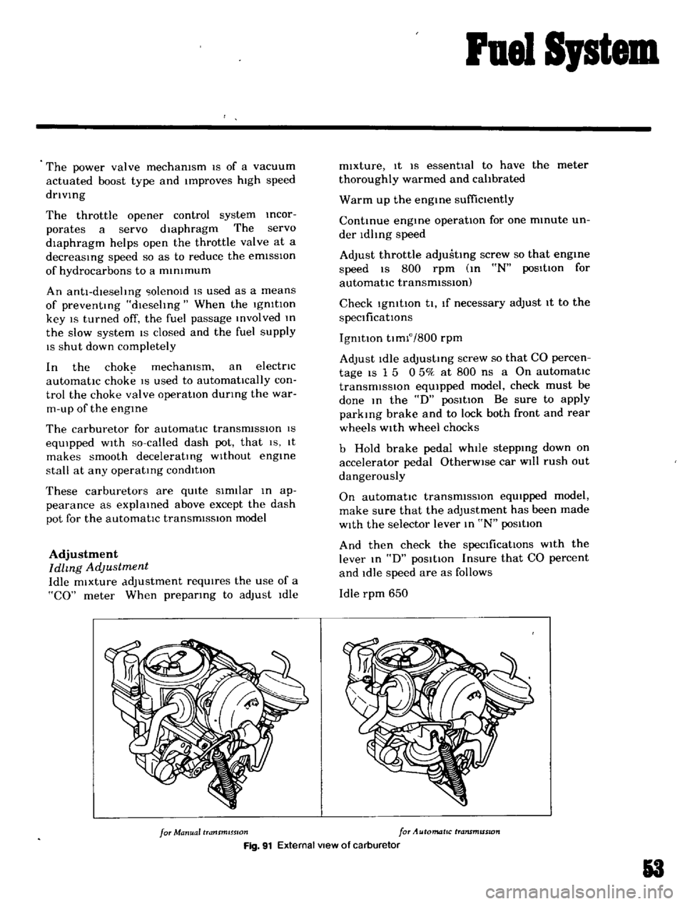
for
Manual
transmISSion
for
Automatic
transmISSion
Fig
91
External
view
of
carburetor
3
Page 129 of 136
Specifications
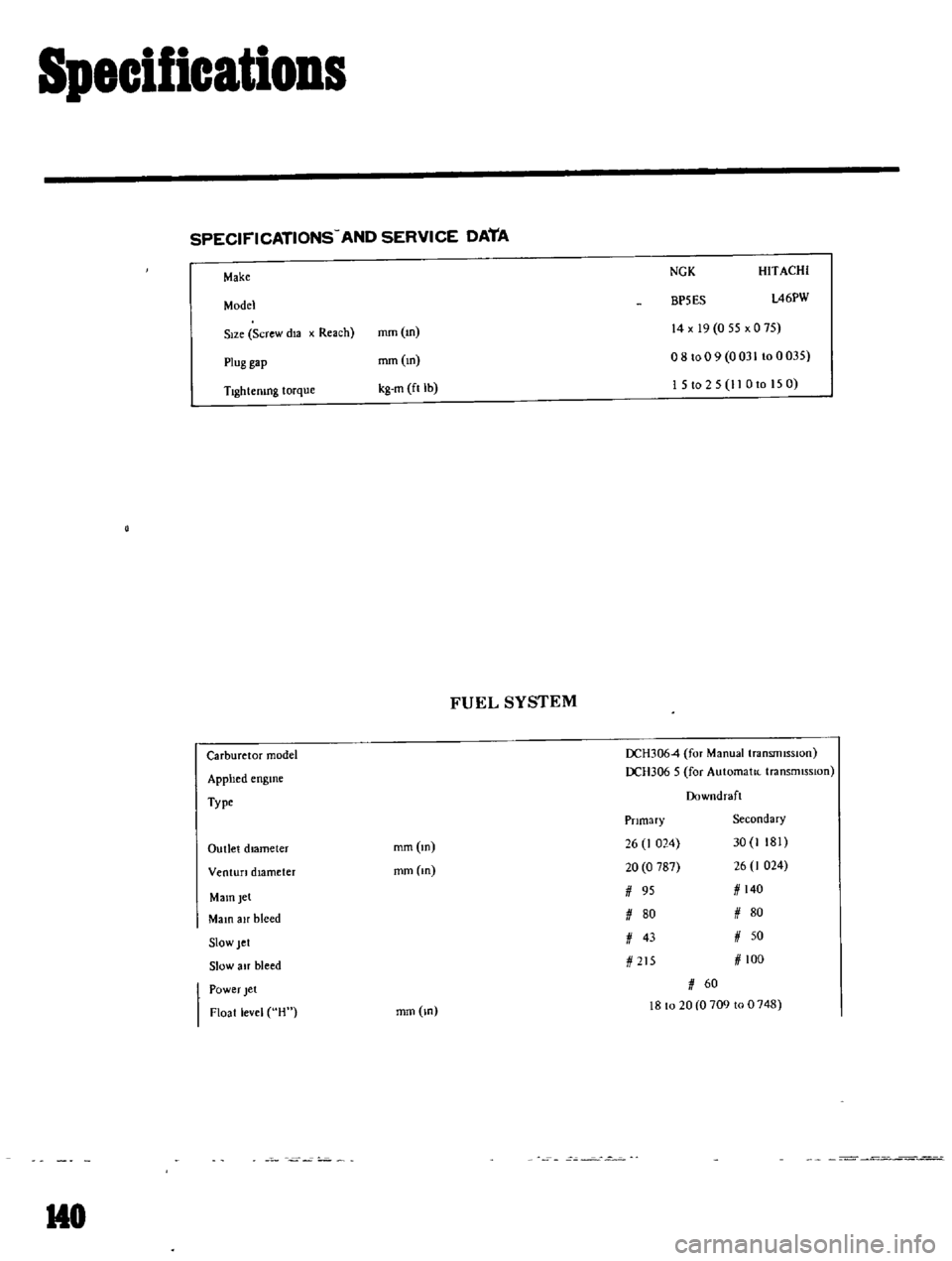
SPECIFICATIONS
AND
SERVICE
DATA
Make
NGK
Model
BP5ES
HITACHI
l46PW
S
ze
Screw
dla
x
Reach
mm
m
14
x
19
0
55
x
0
75
o
8
to
0
9
0
031
10
0
035
15t025
11
Oto
150
Plug
gap
mm
10
Tlghtemng
torque
kg
m
ft
lb
FUEL
SYSTEM
Carburetor
model
DCH3064
for
ManuallransrnlSSlon
DCH306
5
for
Automalle
transmisSIon
Downdraft
Apphed
englOe
Type
Primary
Secondary
Outlet
dIameter
10m
10
10m
10
26
J
024
30
1
181
20
0
787
26
I
024
95
140
fI
80
fI
80
fI
43
fI
50
Venturi
diameter
MamJet
MalO
air
bleed
Slow
let
Slow
alf
bleed
215
100
Power
Jet
Float
level
H
mm
lO
60
18
to
20
0
709
to
0
748
HO
Page 132 of 136
Specifications
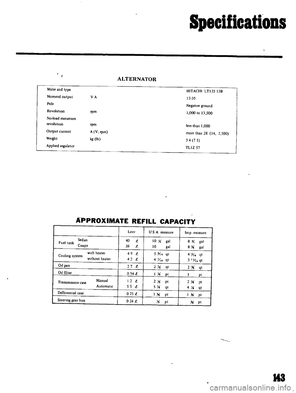
ALTERNATOR
Make
and
type
NonunaJ
output
VA
Pole
Revolution
rpm
No
load
mmunum
revolu
bon
rpm
Output
current
A
V
rpm
Weight
kg
lb
Applied
regulator
HITACHI
LTl3S
13B
12
35
NegatIve
ground
1
000
to
13
500
less
than
I
000
more
than
28
14
2
500
34
7
5
TLI
Z
57
APPROXIMATE
REFILL
CAPACITY
Dter
USA
measure
lmp
measure
Sedan
40
t
10
X
gal
8Y
gal
Fuel
tank
Coupe
38
t
10
gal
8
gal
with
heater
49
t
5
X
qt
4
X
qt
Coohng
system
without
heater
42
t
4
yt
qt
3
X
qt
Od
pan
27
t
2X
ql
2
qt
Od
filter
054
t
IX
pt
I
pi
Transmission
case
Manual
12
t
2X
pt
2X
t
Automatic
55
t
5X
qt
4X
ql
Dlfferenttal
case
o
75
t
I
pI
IX
pI
Steenng
gear
box
024
L
X
pi
X
pt
H3