Page 31 of 136

BDgiDe
TIghtening
torque
40
to
43
ft
Ib
Install
the
push
rod
Install
the
rocker
haft
assembly
and
tighten
the
I
ocker
haft
bracket
bolts
to
the
specIfied
torque
Tightening
torque
15
to
18
ft
lb
Note
TIghtening
operation
should
be
made
gradually
10
separating
two
or
three
stages
and
outwardly
from
the
center
bracket
In
tall
the
Intake
and
exhaust
mamfolds
TIghtening
torque
65
to
10
ft
lb
AdJu
t
valve
clemance
wIth
the
specIfied
dlmenblOn
Install
the
rocker
cover
and
carburetor
assem
bly
I
n
tdll
the
watel
pump
and
thermostat
Tlghtemng
tOl
que
65
to
10
ft
lb
I
nstall
the
crankshaft
pulley
Tighten
the
crank
pulley
bolt
to
the
specIfied
torque
TIghtenIng
torque
109
to
116
ft
lb
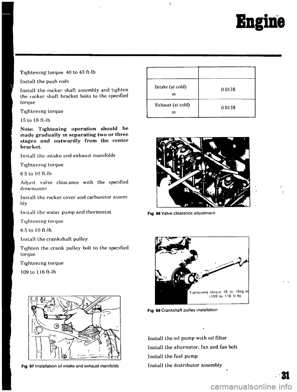
Fig
67
Installation
of
Intake
and
exhaust
manifolds
Intake
at
cold
00138
In
Exhaust
at
cold
00138
In
Fig
68
Valve
clearance
adjustment
TlqhtCnlnq
torque
15
to
16kg
m
109
to
116ltlb
Fig
69
Crankshaft
pulley
installation
Install
the
at
pump
with
011
filter
Install
the
alternator
fan
and
fan
belt
Install
the
fuel
pump
Install
the
dlstnbutor
assembly
31
Page 36 of 136

B1eetrical
Iptem
Removal
DIsconnect
the
battery
ground
cable
Disconnect
the
black
and
yellow
wIre
from
the
magnetic
sWitch
termmal
and
black
battery
cable
from
the
battery
termmal
Remove
two
bolts
used
to
secure
the
startmg
motor
on
the
clutch
housing
Pull
the
starter
assembly
forward
and
remove
the
starting
motor
Installation
InstallatlOn
IS
the
reversal
of
removal
Removal
Disconnect
the
negatIve
battery
termmal
DIsconnect
two
lead
wires
and
connector
from
the
alternator
Loosen
the
adjusting
bolt
Remove
the
alternator
drIve
belt
Remove
the
alternator
installation
bolt
Dismount
the
alternator
from
the
vehIcle
Installation
InstallatlOn
1S
the
reverse
of
removal
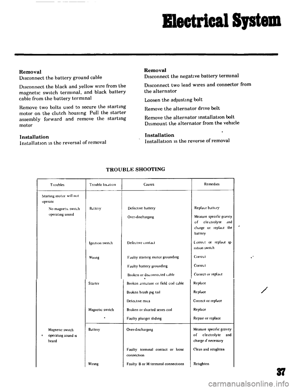
TROUBLE
SHOOTING
Troubles
Trouble
IOl
JlltHI
lartlTlg
motor
will
not
operate
No
mJgnetJl
sWltdl
operating
sound
Rdttcry
IgnitIon
sWltLh
Wiring
Starler
Magnetic
SWitch
Magnetic
SWitch
operating
sound
IS
heard
Bdttery
Wifing
CaUlies
Remedies
Defective
bclttery
Rcpldt
C
bJlh
ry
Over
dlschargmg
Measure
speCific
grJvlty
of
clcl
lrolyte
dnd
chJrge
ur
repl
H
e
the
battery
Defedlvc
lontJd
orreLl
or
replJl
c
Ig
mllun
wltdl
F
lulty
Slartmg
motor
groundlllg
CorrCl
l
F
lUlty
battery
groundmg
Corrcll
Broken
or
dlM
onncdcd
t
Jble
Carrece
or
replJt
c
Broken
dnnJture
or
field
coli
cJble
RcpldCC
Broken
brush
pig
tall
Rcpldce
Dekl
llVe
mll
3
Correcl
or
repldce
Broken
or
shorted
senes
cod
Replace
FaulIy
plunger
slidmg
RepaIr
or
replace
Over
dlschargmg
Measure
speCifiC
gravity
of
electrolyte
and
charge
If
necessary
Faulty
terminal
contact
or
loose
connectIOn
Clean
and
retighten
Faulty
B
or
M
termmal
connections
Rellghten
37
Page 39 of 136

Blectrical
Sptem
Troubles
Trouble
locatIon
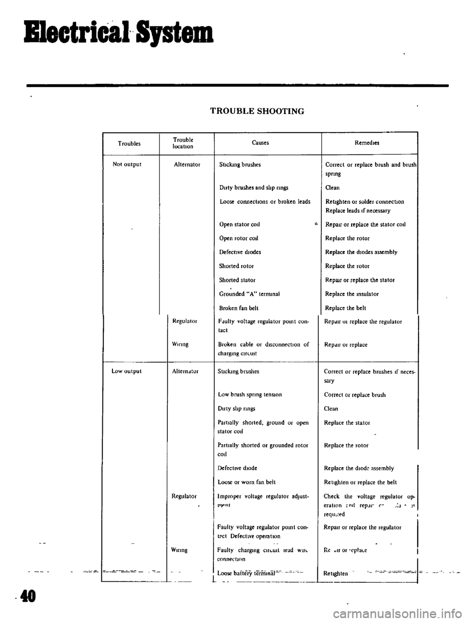
Not
output
Alternator
Regulator
WIring
Low
output
Alterndtor
Regulator
Wifing
TROUBLE
SHOOTING
Causes
Sl1ckmg
brushes
Duty
brushes
and
slIp
nngs
Loose
connections
or
broken
leads
Open
stator
coLI
Open
rotor
cotl
DefectIVe
dJodes
Shorted
rotor
Shorted
stator
Grounded
A
ternunal
Broken
fan
belt
FJulty
voltage
regulator
pomt
con
tact
Broken
cable
or
disconnectIOn
of
chargIng
CIH
UIt
StIcking
brushes
Low
brush
spring
tenSion
Duty
slIp
nngs
Partially
shorted
ground
or
open
stator
cod
Partially
shorted
or
grounded
rotor
c01l
DefectIVe
dIOde
Loose
or
worn
fan
belt
Improper
voltage
regulator
adlust
Pl
n
I
Faulty
voltage
regulator
pomt
con
t
ct
Defective
operation
Faulty
chargmg
CUI
Ult
lead
WIn
connection
Remedies
Correct
or
replace
brush
and
brush
spnng
aean
RetIghten
or
solder
connection
Replace
leads
If
necessary
6
RepaIr
or
replace
the
stator
coLi
Replace
the
rotor
Replace
the
dIOde
assembly
Replace
the
rotor
RepaIr
or
replace
the
stator
Replace
the
Insulator
Replace
the
belt
RepdU
01
replace
the
regulator
Repdtr
or
replace
Correct
or
replace
brushes
If
neces
sary
Correct
or
replace
brush
Clean
Replace
the
stator
Replace
the
rotor
Replace
the
dIode
assembly
Rettghlen
or
replace
the
belt
Check
the
voltage
regulalor
op
eratIOn
no
rep
Jr
r
J
j
required
Repair
or
replace
the
regulator
Re
olf
or
rpla
e
t
J
Loose
baltery
leririmaJ
Rettghten
1