Page 38 of 136

llectrical
Spt
When
Harting
lWltch
I
IgllltlUn
iwltch
FJuhy
rctuflung
Repldce
set
10
OFf
the
slJrl
motor
do
nut
MJgnclK
Wltdl
Seiad
contJr
l
Repldcc
IIlg
I
op
Shorted
1
011
Replace
Faulty
plunger
slidmg
Replace
StJflillg
motOr
Pillion
does
not
dlsengJge
from
the
Repair
or
replace
nng
gedr
smoothly
Pinion
sphne
dot
110t
disengage
Repan
or
replJce
moothly
SCl7Cd
pinIOn
metal
Replace
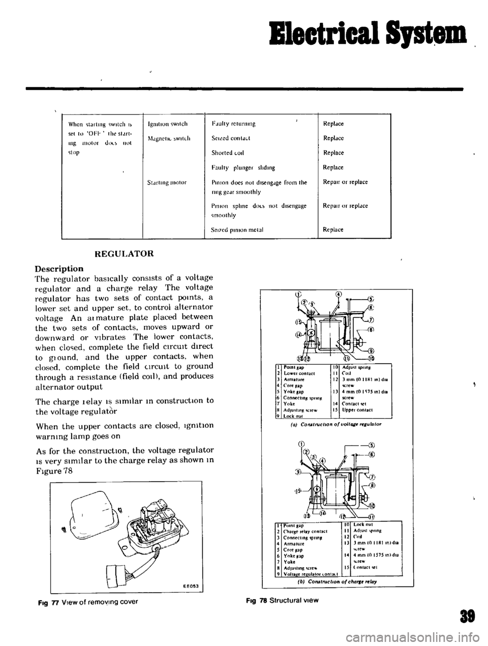
REGULATOR
Description
The
regulator
basically
consists
of
a
voltage
regulator
and
a
charge
relay
The
voltage
regulator
has
two
sets
of
contact
poInts
a
lower
set
and
upper
set
to
control
alternator
voltage
An
at
mature
plate
placed
between
the
two
sets
of
contacts
moves
upward
or
downward
or
Vibrates
The
lower
contacts
when
clo
ed
complete
the
field
CIrCUIt
dIrect
to
glOund
and
the
upper
contacts
when
closed
complete
the
field
CIrCUIt
to
ground
through
a
resIstam
e
field
COl
and
produces
alternator
output
The
charge
lelay
IS
SimIlar
In
constructIOn
to
the
voltage
regulator
When
the
upper
contacts
are
closed
IgnitIOn
warnIng
lamp
goes
on
As
for
the
constructIOn
the
voltage
regulator
IS
very
SImIlar
to
the
charge
relay
as
shown
In
Figure
78
I
POlnlsap
2
lower
nt
CI
3
Arm2fu1C
4
COfe
ap
5
Yokeg
lp
6
Connecting
pnn
t
T
Yolce
8
AdJu
fln
rcw
9
Lock
nul
Crew
13
4mmlOlli15
nldll
SCrew
14
RlaCI
I
15
Upper
Rlact
a
COlUlruci
o
o
voltage
ulato
O
0
1
EEOSJ
I
Point
gap
2
Char
Clay
nl3el
3
ConMctmg
pun
4
Armature
nl
daa
5
Core
ap
re
6
Yoke
Jap
14
4
mm
0
1575
n
dla
7
Yoke
rew
8
AdJu
llng
Cre
IS
nfaC
t
e1
9
Voila
ere
ulal0t
l
ontal
1
b
COfUtruclton
of
cha
rt
ay
FIg
n
View
of
removing
cover
FIg
78
Structural
view
81
Page 40 of 136
i
J
t
1
p
3
t
t
i
I
EXCCS
lVe
output
Alterndlor
P
Short
l
lfculted
or
broken
neutral
Replace
the
wife
Wife
Reguldtor
Impro
er
voltdge
regulator
adJust
ment
Defective
operatIon
9i
reg
ator
oP
P
lor
replace
as
rw
t
Check
the
charge
relay
operation
and
repair
or
replace
as
requIred
Check
the
voltage
t
fa
hon
and
ep
lf
required
Improper
charge
relay
adjustment
detecttve
operatIOn
and
or
faulty
pomt
contact
t
f
J
r
p
i
lC
I
1
1
r
i
r
A
1
A
f
l
1
1
S
1
P
1
Page 133 of 136
Specifications
REGULATOR
VOIt
tgl
n
gulJtur
Model
HITACHI
TLlZ
57
RegulJLlIlg
voltage
with
fully
charged
h
lttcry
Jnd
regulator
faced
do
IlwJrd
Y
143
to
15
3
al
20
68
J
Voltage
cod
resistance
n
10
5
at
200C
680F
10
31
Rotor
coli
msertmg
resIstance
n
Voltage
coil
senes
resistance
Smootlung
resistance
n
40
Core
gap
mm
m
mm
m
o
6
to
0
0
0236
to
0
0394
03to04
00118toOOI57
Poml
gap
Charge
relay
Release
voltage
Voltage
COlI
resIstance
v
n
42
to
5
2
at
N
termmal
Core
gap
Pomt
gap
mm
m
mm
m
378
at
200C
680F
0810
I
0
00315
to
0
0394
04
to
0
6
0
0
57
to
0
0236
Standard
temperature
gradient
0015
V
oC
144