1969 DATSUN B110 fuel pressure
[x] Cancel search: fuel pressurePage 6 of 136

fable
of
Contents
BODY
WORK
SPECIFICATIONS
I
HOOD
112
SERVICE
DATA
130
Removal
112
ENGINE
134
InstallatIOn
112
General
SpeCificatIOn
134
HOOD
LOCK
112
Tlghtemng
Torque
134
Removal
112
SpeCIficatIOn
135
Adjustment
112
Coohng
System
139
LubncatlOn
114
Fuel
System
140
TRUNK
LID
LOCK
116
Starter
142
Removal
116
Alternator
143
Adjustment
116
Regulator
144
TRUNK
LID
TORSION
BAR
116
Dlstnbutor
145
DOOR
CONSTRUCTION
117
IgnItIOn
Cot
145
WIRING
DIAGRAMS
118
CLUTCH
146
BULB
SPECIFICATIONS
120
NOTES
174
HEADLAMP
121
THERMOMETER
AND
FUEL
METER
122
OIL
PRESSURE
AND
IGNITION
WARNING
LAMPS
126
I
I
t
I
3
Page 14 of 136
IQgiDe
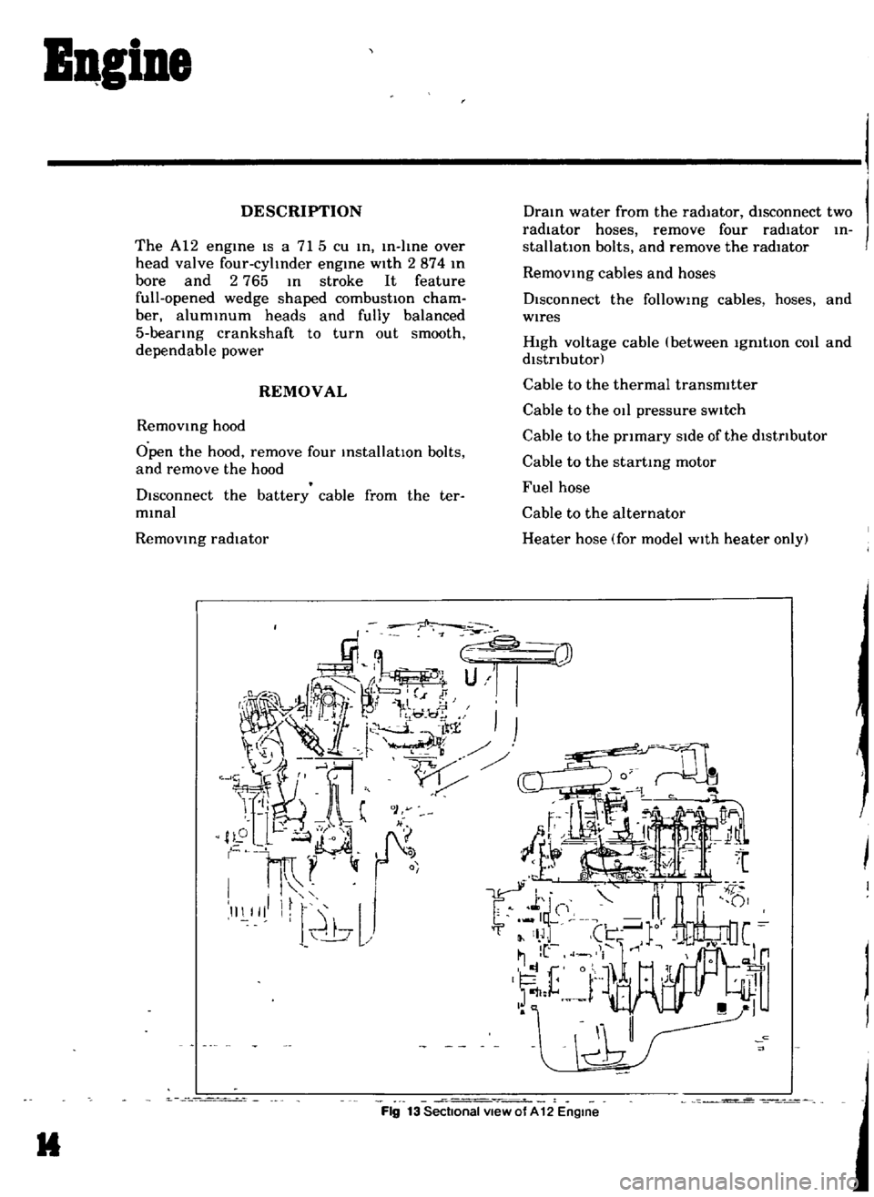
DESCRIPTION
The
A12
engme
IS
a
715
cu
m
In
I
me
over
head
valve
four
cyltnder
engine
with
2874
m
bore
and
2
765
m
stroke
It
feature
full
opened
wedge
shaped
combustIOn
cham
ber
alummum
heads
and
fully
balanced
5
bearmg
crankshaft
to
turn
out
smooth
dependable
power
REMOVAL
Removmg
hood
Open
the
hood
remove
four
mstallatlOn
bolts
and
remove
the
hood
Disconnect
the
battery
cable
from
the
ter
mmal
Removmg
radIator
Dram
water
from
the
radiator
disconnect
two
radIator
hoses
remove
four
radIator
m
stallatlOn
bolts
and
remove
the
radiator
Removmg
cables
and
hoses
Disconnect
the
followmg
cables
hoses
and
wires
High
voltage
cable
between
Igmtton
COlI
and
distributor
Cable
to
the
thermal
transmitter
Cable
to
the
011
pressure
sW1tch
Cable
to
the
primary
Side
of
the
distributor
Cable
to
the
startmg
motor
Fuel
hose
Cable
to
the
alternator
Heater
hose
for
model
With
heater
only
I
Fig
13
Sectional
view
of
A
12
Engine
It
Page 45 of 136
Icnition
Sptem
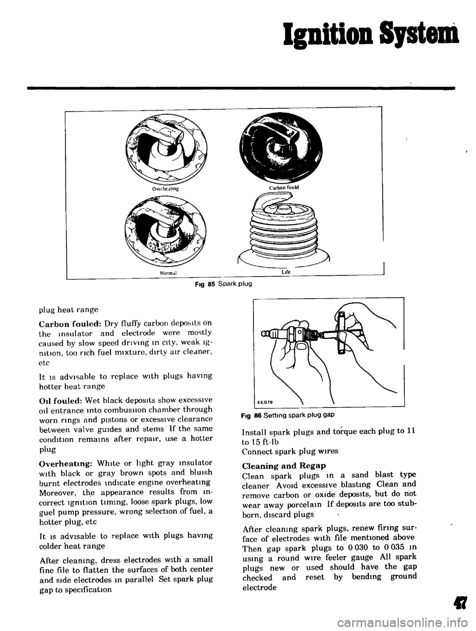
Ovcrhc
Jtmg
Norm
Jl
i
r
rJ
I
ttr
I
i
V
Carbon
fould
Fig
85
Spark
plug
Life
plug
heat
range
Carbon
fouled
Dry
fluffy
carbon
depo
lts
on
the
Insulator
and
electrode
were
mostly
caused
by
slow
speed
dnvlng
In
cIty
weak
Ig
nltlOn
too
nch
fuel
mixture
dirty
aIr
cleaner
etc
It
IS
advIsable
to
replace
WIth
plugs
havmg
hotter
heat
range
011
fouled
Wet
black
depoSits
show
excesSive
oIl
entrance
Into
combusllon
chamber
through
worn
rmgs
and
pIstons
or
excessIve
clearance
between
valve
gUIdes
and
stems
If
the
same
condition
remams
after
repair
use
a
hotter
plug
Overheatmg
WhIte
or
hght
gray
msulator
WIth
black
or
gray
brown
spots
and
blUIsh
burnt
electrodes
indIcate
engme
overheatIng
Moreover
th
e
appearance
results
from
in
correct
IgnitIon
tIming
loose
spark
plugs
low
guel
pump
pressure
wrong
selectIOn
of
fuel
a
hotter
plug
etc
It
IS
adVisable
to
replace
WIth
plugs
havmg
colder
heat
range
After
cleaning
dress
electrodes
With
a
small
fine
file
to
flatten
the
surfaces
of
both
center
and
Side
electrodes
In
parallel
Set
spark
plug
gap
to
specification
FIg
86
Settmg
spark
plug
gap
Install
spark
plugs
and
torque
each
plug
to
11
to
15
ft
Ib
Connect
spark
plug
wires
Cleaning
and
Regap
Clean
spark
plugs
In
a
sand
blast
type
cleaner
A
VOId
excessIve
blasting
Clean
and
remove
carbon
or
OXide
depoSits
but
do
not
wear
away
porcelain
If
depos1ts
are
too
stub
born
discard
plugs
After
cleaning
spark
plugs
renew
firing
sur
face
of
electrodes
With
file
mentioned
above
Then
gap
spark
plugs
to
0
030
to
0
035
In
uSing
a
round
wire
feeler
gauge
All
spark
plugs
new
or
used
should
have
the
gap
checked
and
reset
by
bending
ground
electrode
II
Page 48 of 136
Fuel
Sptem
Testing
A
fuel
pump
IS
operatIng
properly
when
1tS
pressure
IS
Within
specifications
and
ItS
capacIty
IS
equal
to
the
engine
s
reqUIrements
at
all
speeds
Pressure
and
capacity
must
be
determined
by
two
tests
With
the
pump
mounted
on
the
engIne
Be
sure
that
there
IS
gasohne
m
the
tank
when
conductIng
these
tests
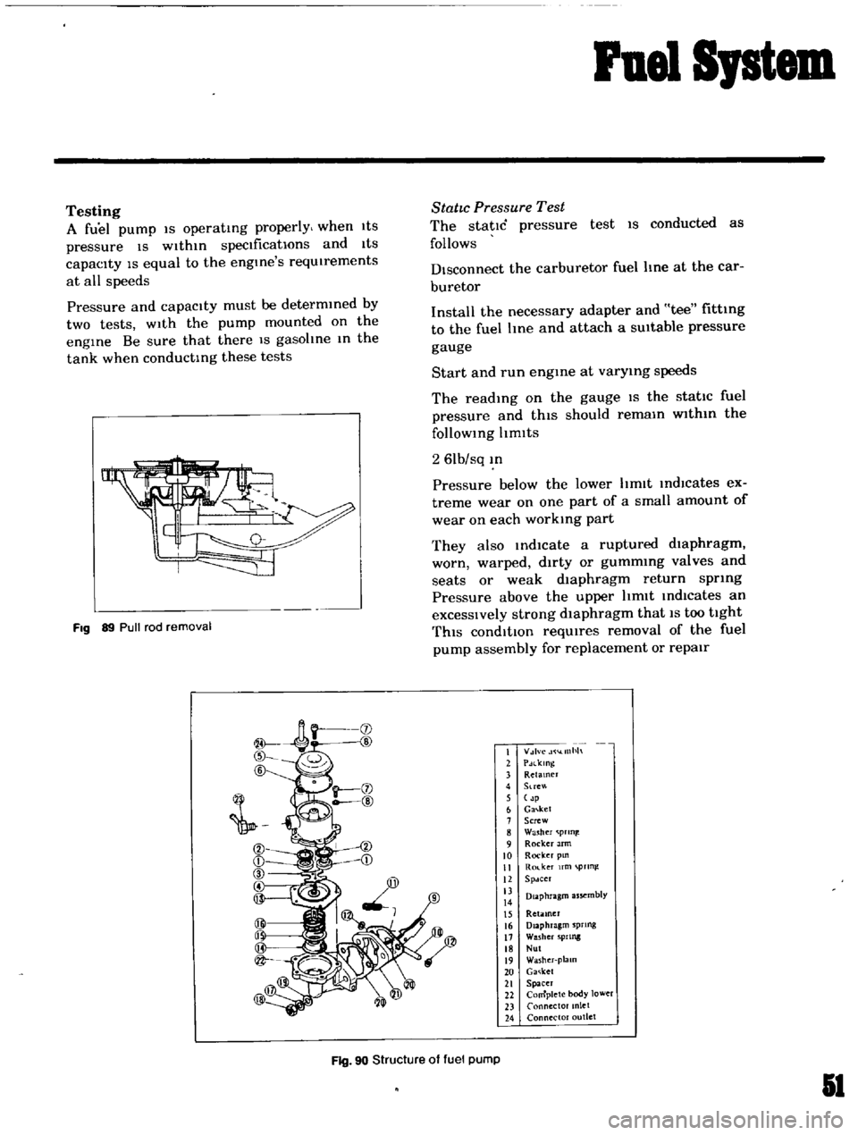
Fig
89
Pull
rod
removal
StatIc
Pressure
Test
The
static
pressure
test
IS
conducted
as
follows
Disconnect
the
carburetor
fuel
line
at
the
car
buretor
Install
the
necessary
adapter
and
tee
fitting
to
the
fuel
Ime
and
attach
a
SUitable
pressure
gauge
Start
and
run
engme
at
varymg
speeds
The
readIng
on
the
gauge
IS
the
static
fuel
pressure
and
thIS
should
remam
wlthm
the
follOWing
Itmlts
2
61b
sq
m
Pressure
below
the
lower
hmlt
IndlCates
ex
treme
wear
on
one
part
of
a
small
amount
of
wear
on
each
working
part
They
also
md1cate
a
ruptured
dIaphragm
worn
warped
dirty
or
gummmg
valves
and
seats
or
weak
dIaphragm
return
spring
Pressure
above
the
upper
hmlt
Indicates
an
excessIVely
strong
dIaphragm
that
IS
too
tight
ThIS
condItIOn
reqUIres
removal
of
the
fuel
pump
assembly
for
replacement
or
repair
I
V
lvc
llllh
2
PdlklOg
3
Retamer
4
Stre
5
p
6
Ga
ket
7
Screw
8
Washer
prln
9
Rocker
Jrm
10
Rocker
pm
II
Ro
ker
fm
pTln
12
Spdcer
13
Diaphragm
assembly
14
15
Retiuner
16
Diaphragm
sprtng
17
Washer
5PIlllg
18
Nul
19
Washer
plalO
20
Ga
ket
21
Spacer
22
Complete
body
lower
23
Connector
anlet
24
Connector
outlet
Fig
90
Structure
of
fuel
pump
51
Page 57 of 136
Fuel
SJstem
Check
float
needle
and
seat
for
wear
Replace
the
assembly
If
worn
Check
the
throttle
and
choke
bores
In
throttle
body
and
cover
castIng
for
wear
or
out
of
round
Inspect
Idle
adjustIng
needles
for
burrs
or
ndges
Replace
as
reqUIred
Inspect
gaskets
to
ensure
that
they
do
not
ap
pear
hard
or
bnttle
and
that
the
edges
are
not
turned
or
dIstorted
If
any
such
condItIOn
IS
detected
they
must
be
replaced
Check
filter
secreen
screen
for
cloggIng
Clean
and
If
It
IS
dIstorted
or
remaInS
plugged
replace
Check
cluster
for
loose
or
worn
parts
If
damage
or
Ioosene
s
eXists
replace
cluster
assembly
Check
the
hnkage
for
operatIng
condItion
Inspect
the
operatIOn
of
acceleratIng
pump
Pour
gasohne
Into
the
float
chamber
and
operate
the
throttle
hver
Check
conditIOn
of
gasohne
InjectIOn
from
the
acceleratIng
nozzle
Assembly
and
Installation
Assemble
and
Install
the
carburetor
In
I
everse
sequence
of
dIsassembly
and
removal
Replace
the
gaskets
If
necessary
When
dlsassembhng
and
reassembhng
the
In
terlock
hnk
and
related
components
be
careful
not
to
bend
or
deform
the
components
Reassembly
carefully
and
correctly
so
that
all
Interlock
hnks
operate
smoothly
Jets
The
carburetor
performance
depends
on
Jets
and
aIr
bleed
and
the
vehicle
emISSIOns
largely
depends
on
the
carburetor
performan
ce
That
IS
why
these
components
are
manufactured
WIth
utmost
care
To
clean
them
use
gasohne
and
blow
aIr
on
them
ChangIng
Jet
or
air
bleed
sIze
may
cause
III
vehICle
emIssIon
So
they
should
not
be
changed
theIr
numbers
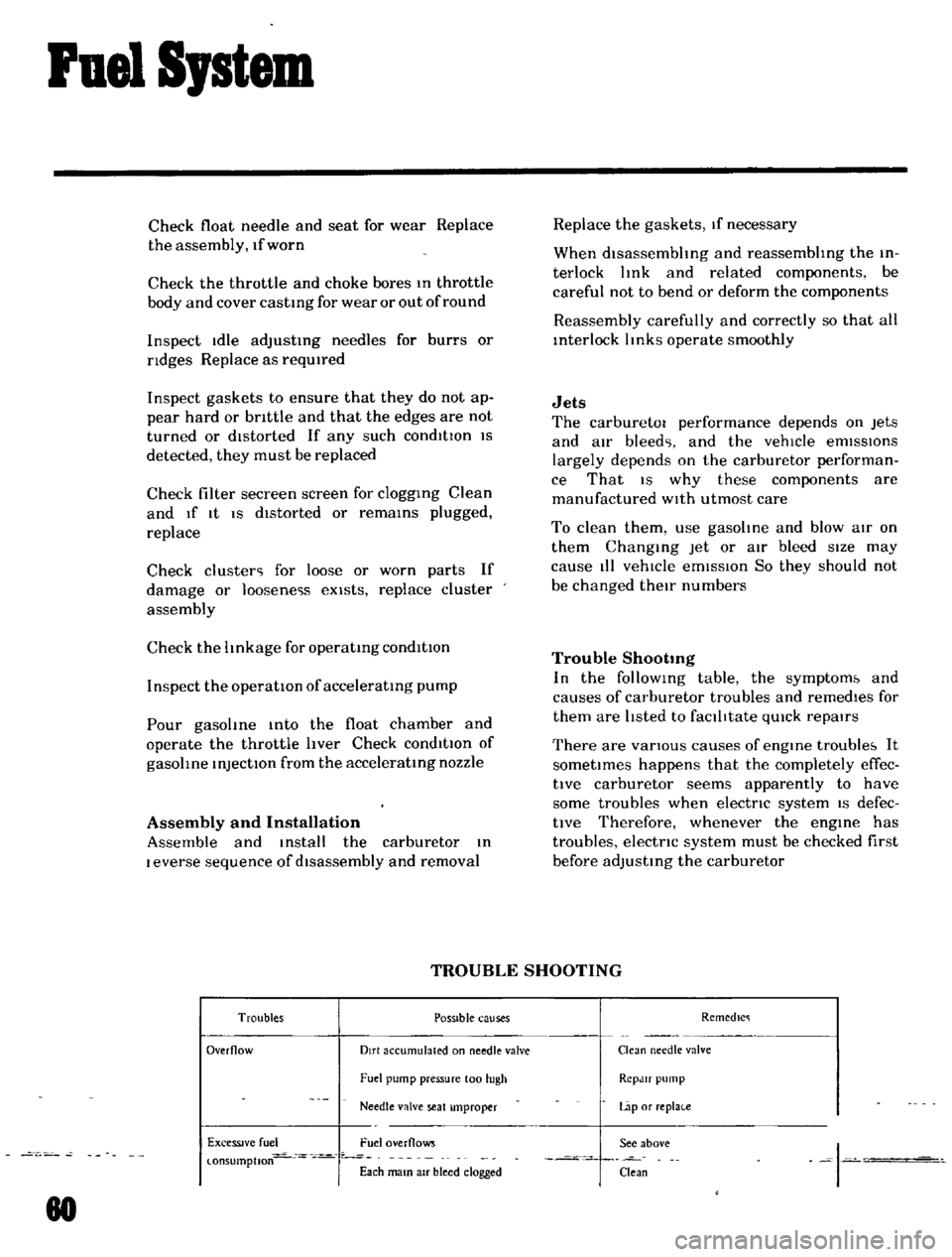
Trouble
Shootmg
In
the
follOWIng
table
the
symptom
and
causes
of
carburetor
troubles
and
remedIes
for
them
are
hsted
to
faclhtate
qUIck
repaIrs
There
are
vanous
causes
of
engIne
trouble
It
sometImes
happens
that
the
completely
effec
tlve
carburetor
seems
apparently
to
have
some
troubles
when
electnc
systern
IS
defec
tIve
Therefore
whenever
the
engIne
has
troubles
electnc
system
must
be
checked
first
before
adjusting
the
carburetor
TROUBLE
SHOOTING
Troubles
POSSible
causes
Remedlc
Overflow
Dirt
accumulated
on
needle
valve
Clean
needle
valve
Fuel
pump
pressure
100
hIgh
RCpJlf
pump
Needle
valve
seat
Improper
Lap
or
replai
e
ExceSSIve
fuel
Fuel
overflows
See
above
I
l
onsumptlon
Each
mam
aIr
bleed
clogged
Clean
80
Page 130 of 136
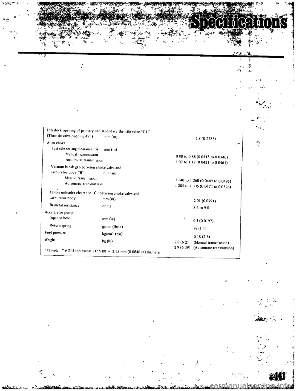
1l
J
1
II
i
r
r
Interlock
opening
of
primary
wd
sCl
ondary
throttle
valve
e
I
Throttle
valve
opening
48
mill
Ul
Auto
choke
rac
lldle
sclllllg
dCdrdllLC
A
111m
Ill
Mdlludllfdnsmlsslon
AUttJl1ldtlC
lrdnsmlSS10n
58
0
81
080
to
0
88
0
0315
to
0
0346
107
to
1
17
0
0421
to
0
0461
Vawurn
brcdk
gap
between
hoke
vdlve
and
l
drhurelor
body
8
mill
10
Manudl
transml
SIOn
AutomatlL
trdnMlll
JOn
I
140
to
I
260
0
0449
to
00496
1205
to
I
115
004741000526
Choke
unloader
clearance
C
between
choke
valve
and
l
Jrburetor
body
mm
In
BI
metal
rCSlstan
c
ohms
201
00791
8
6
to
9
0
A
leteralor
pump
I
oJCl
tor
hole
Return
spring
Fuel
pressure
mm
05
00IQ7
78
I
I
018
2
6
Manual
transmISsion
AutomatIc
transmIssIon
WClght
g
mm
Ibfm
kg
em
pSI
kg
lb
28
6
2
29
639
f
x3mplc
15
replC
ts
15
1
00
2
15
mm
0
0846
m
dIameter
J
t
IHI
n
h
1i
1
2
c
L
if
J
l
lQ
w
l
d
J01
i