1969 DATSUN B110 wheel bolts
[x] Cancel search: wheel boltsPage 27 of 136
Bogine
Note
Set
the
locate
plate
so
as
the
LOWER
mark
comes
to
the
engine
bot
tom
side
Set
the
maIn
bearIngR
on
theIr
posItIOns
on
the
cylinder
block
Notes
a
The
center
bearmg
No
3
bearmg
is
a
flanged
type
for
thrust
force
b
Two
lOner
bearmgs
No
2
and
No
4
are
of
the
same
type
c
The
front
bearmg
No
1
IS
the
same
type
as
the
rear
bearmg
No
5
d
All
bearings
except
for
No
I
bearing
are
interchangeable
between
upper
and
lower
bearings
Apply
engIne
OIl
to
the
mam
bearIng
surfaces
on
both
sIdes
of
the
cyltnder
block
and
cap
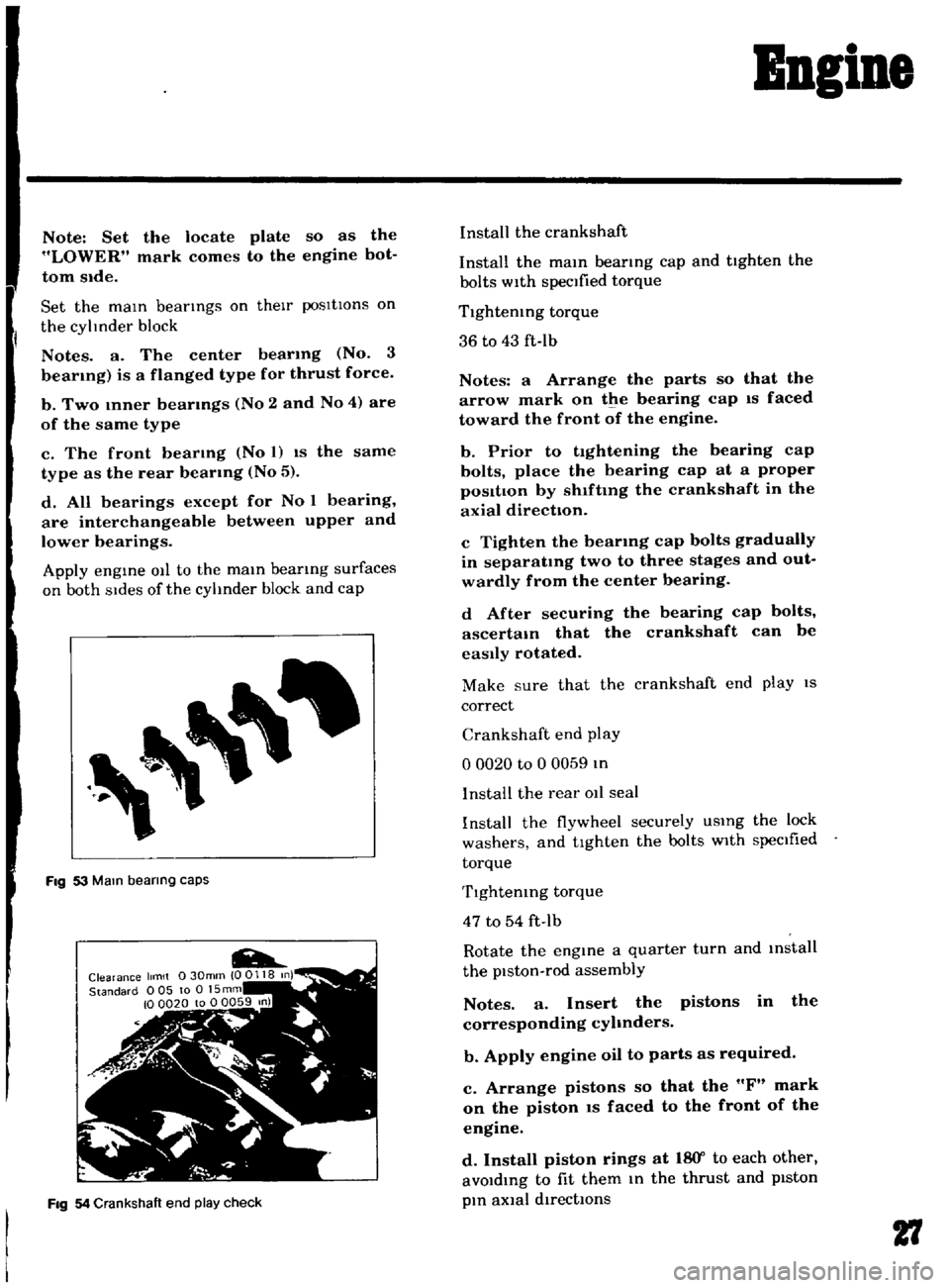
Fig
53
Mam
bearing
caps
Fig
54
Crankshaft
end
play
check
Install
the
crankshaft
Install
the
mam
bearmg
cap
and
tighten
the
bolts
with
specified
torque
Tlghtemng
torque
36
to
43
ft
Ib
Notes
a
Arrange
the
parts
so
that
the
arrow
mark
on
the
bearing
cap
IS
faced
toward
the
front
of
the
engine
b
Prior
to
tightening
the
bearing
cap
bolts
place
the
bearing
cap
at
a
proper
posItIon
by
shlftmg
the
crankshaft
in
the
axial
direction
c
Tighten
the
bearmg
cap
bolts
gradually
in
separatmg
two
to
three
stages
and
out
wardly
from
the
center
bearing
d
After
securing
the
bearing
cap
bolts
ascertam
that
the
crankshaft
can
be
easily
rotated
Make
sure
that
the
crankshaft
end
play
IS
correct
Crankshaft
end
play
o
0020
to
0
0059
In
I
nstalI
the
rear
011
seal
Install
the
flywheel
securely
USIng
the
lock
washers
and
tighten
the
bolts
with
specIfied
torque
Tlghtemng
torque
47
to
54
ft
Ib
Rotate
the
engine
a
quarter
turn
and
mstall
the
piston
rod
assembly
Notes
a
Insert
the
pistons
in
the
corresponding
cyhnders
b
Apply
engine
oil
to
parts
as
required
c
Arrange
pistons
so
that
the
F
mark
on
the
piston
IS
faced
to
the
front
of
the
engine
d
Install
piston
rings
at
18
Y
to
each
other
avoIdIng
to
fit
them
In
the
thrust
and
pIston
pIn
aXial
directIOns
27
Page 74 of 136
Brakes
Adjusting
shIm
thickness
for
selectIOn
o
0197
In
00315
In
o
0630
In
Note
When
adjusting
be
sure
to
use
ad
Jusbng
sh1ms
having
same
th1ckness
for
upper
and
lower
brake
master
cylinder
IOstallahon
bolts
Upon
completIOn
of
adjusting
shIm
adjust
ment
tighten
the
stopper
down
to
such
an
ex
tent
that
heIght
of
the
pedal
head
IS
5
57
pO
0787
In
and
tighten
the
lock
nut
becurely
Free
travel
of
the
brake
pedal
IS
0
197
to
0591
tn
and
the
stroke
IS
4
72
In
Hand
Brake
Turn
the
turn
buckle
properly
and
adjust
hand
brake
lever
operatmg
stroke
correctly
so
that
operatmg
stroke
IS
3
091
m
16
notches
at
operatIng
force
of
243
to
331
Ib
Upon
com
pletIOn
of
adjustment
be
sure
to
tIghten
the
lock
nut
Upon
completIOn
of
the
adjustment
release
the
hand
brake
lever
and
make
sure
that
the
rear
wheels
are
not
braked
Normal
btroke
3091
In
6
notches
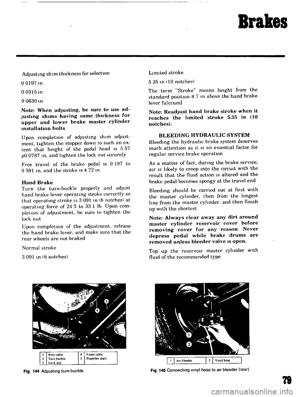
Fig
144
AdJusting
turn
buckle
LImIted
stroke
535
tn
10
notches
The
term
Stroke
means
heIght
from
the
standard
posItIon
8
7
In
above
the
hand
brake
lever
fulcrum
Note
Readjust
hand
brake
stroke
when
it
reaches
the
hmited
stroke
5
35
in
10
notches
BLEEDING
HYDRAULIC
SYSTEM
BleedIng
the
hydrauhc
brake
system
deserves
much
attentIOn
as
It
IS
an
e
senttal
factor
for
regular
servICe
brake
operatIon
As
a
matter
of
fact
durmg
the
brake
serVice
air
IS
lIkely
to
creep
Into
the
CirCUIt
WIth
the
result
that
the
flUId
actIon
IS
altered
and
the
brake
pedal
becomes
spongy
at
the
travel
end
Bleedmg
should
be
carned
out
at
first
WIth
the
master
cylmder
then
from
the
longest
lIne
from
the
master
cylmder
and
then
fimsh
up
With
the
shortest
Note
Always
clear
away
any
dirt
around
master
cylinder
reservoir
cover
before
removing
cover
for
any
reason
Never
depress
pedal
while
brake
drums
are
removed
unless
bleeder
valve
IS
open
Top
up
the
reservOIr
master
cyltnder
With
flUId
of
the
recommended
type
Fig
145
Connecting
Vinyl
hose
to
air
bleeder
rear
79
Page 80 of 136
Pront
Suspension
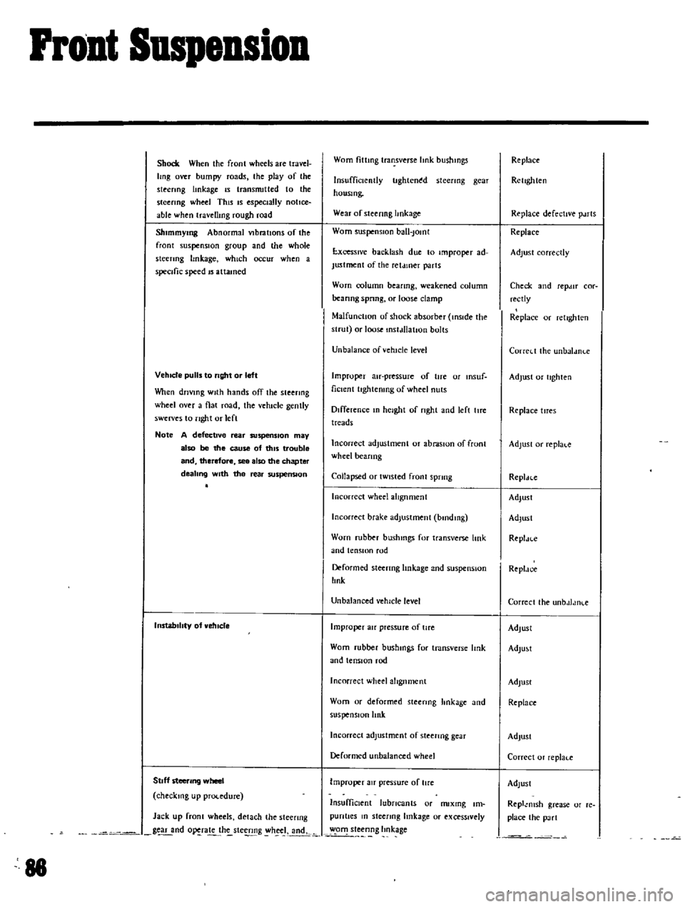
Shock
When
the
fronl
wheels
are
travel
Img
over
bumpy
roads
the
play
of
the
steenng
linkage
IS
transnutted
to
the
steering
wheel
This
IS
especially
notice
able
when
travellmg
rough
road
Shlmmymg
Abnormal
VIbratIOns
of
the
front
suspensIOn
group
and
lhe
whole
sleenng
hnkage
which
occur
when
a
specific
speed
IS
attamed
VehIcle
pulls
to
right
or
left
Vhen
driVing
With
hands
off
the
steering
wheel
over
a
flat
road
the
vehicle
gently
swerves
to
nght
or
lefl
Note
A
defective
rear
suspenSion
may
also
be
the
cause
of
tillS
trouble
and
therefore
see
also
the
chapter
dealing
With
the
rear
suspenSion
InstabilIty
of
vehIcle
Stoff
steering
wheel
checking
up
procedure
Jack
up
fronl
wheels
detach
the
steenng
g
nd
o
ra
h
ste
g
h
J
andk
88
Worn
fittmg
transverse
hnk
bushmgs
Insufficiently
tlghten
d
steenng
gear
housmg
Wear
of
steenng
hnkage
Worn
suspensIOn
ball
Jomt
E
xcesslve
backlash
due
to
improper
ad
Justment
of
the
ret
uner
parts
Worn
column
beanng
weakened
column
beanng
spnng
or
loose
clamp
MalfunctIOn
of
shock
absorber
inSIde
the
strut
or
loose
mstdllatJon
bolts
Unbalance
ofvehtcle
level
Improper
au
pressure
of
tire
or
msuf
ficlent
hghtenmg
of
wheel
nuts
Difference
In
height
of
nght
and
left
lIre
treads
Incorrect
adjustment
or
abraSIOn
of
front
wheel
beanng
Collapsed
or
tWisted
front
sprmg
Incorrect
wheel
alIgnment
Incorrect
brake
adjustment
bmdmg
Worn
rubber
bushmgs
for
transverse
link
and
tensIOn
rod
Deformed
steering
linkage
and
suspensIOn
lInk
Unbalanced
vehicle
level
Improper
au
pressure
of
tire
Worn
rubber
bushmgs
for
tmnsverse
Imk
and
tensIOn
rod
Incorrect
wheel
alignment
Worn
or
deformed
steenng
hnkage
and
suspensIOn
link
Incorrect
adjustment
of
steenng
gear
Deformed
unbalanced
wheel
Improper
au
pressure
of
lire
InsuffiCient
lubricants
or
nuxmg
Im
pun
ties
m
sleenng
linkage
or
exceSSively
o
steenng
Imkage
Replace
Rellghten
Replace
defective
p
uts
Replace
Adjust
correctly
Check
and
repdlT
cor
rectly
Replace
or
relighlen
Correl
t
the
unbaldnl
e
Adjust
or
tighten
Replace
tlTes
Adjust
or
replal
c
Repldcc
Adjust
Adlusl
Repl
n
e
Repldc
e
Correcl
the
unbdJdlKe
Adjust
AdlU
t
Adjust
Replace
AdJusl
Correcl
or
replaf
e
Adlust
Repl
msh
grease
or
re
place
the
pa
rt
Page 85 of 136
SteeriDg
ConditIon
lIeavy
steering
Loose
steenng
Pull
to
one
side
Steermg
shock
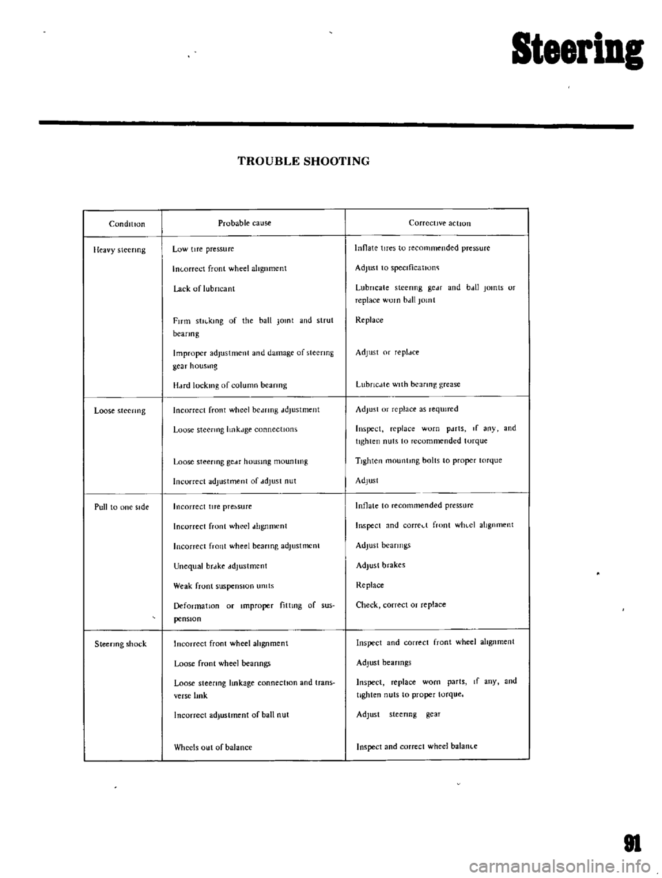
TROUBLE
SHOOTING
Probable
cause
Low
tIre
pressure
In
orreet
front
wheel
altgnmcnt
Lack
of
lubricant
FITm
stll
kmg
of
the
ball
Jomt
and
strut
beanog
Improper
adjustment
and
damage
of
steering
gcar
housmg
H
Hd
lock1l1g
of
column
beanng
Incorrect
front
wheel
be
mng
ddJustment
Loose
steermg
hnkJge
connectIOns
Loose
steermg
gCdf
housmg
mountIng
Incorrect
adjustment
of
ddJust
nut
Incorrect
lITe
pre
sure
Incorrect
front
wheel
dhgnment
Incorrect
front
wheel
beanng
adjustment
Unequal
brdke
ddJustment
Weak
front
suspensIOn
umts
Deformation
or
Improper
fittmg
of
sus
pensIOn
Incorrect
front
wheel
ahgnment
Loose
front
wheel
beanngs
Loose
steering
lmkage
connectIOn
and
trans
verse
lmk
Incorrect
adjustment
of
ball
nut
Wheels
out
of
balance
Corrective
action
Innate
tires
to
recommended
pressure
Adjust
to
speclficatJono
Lubricate
steering
gc
H
and
b
dl
jomts
or
replace
WOln
bdll
jomt
Replace
Adjust
or
repldce
LubrlcJte
with
bearing
grease
Adjust
or
replace
as
reqUired
Inspect
replace
worn
pdrts
If
any
and
tighten
nuts
to
recommended
torque
TIghten
mountmg
bolts
to
proper
torque
Adjust
Inflate
to
recommended
pressurc
Inspect
and
corred
front
WhlCI
alignment
Adjust
bearings
Adjust
brakes
Replace
Check
correct
or
replace
Inspect
and
correct
front
wheel
alIgnment
Adjust
bearings
Inspect
replace
worn
parts
If
any
and
tighten
nuts
to
proper
torque
Adjust
steenng
gear
Inspect
and
correct
wheel
balanl
e
81
Page 120 of 136
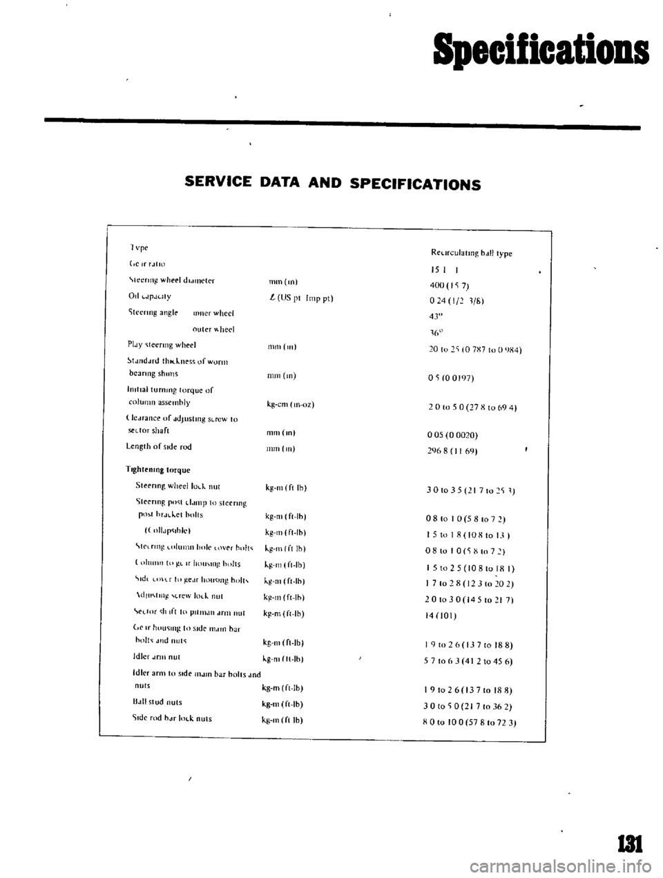
Specifications
SERVICE
DATA
AND
SPECIFICATIONS
1
vpc
RCl
n
ulatlllg
bdll
type
ClrrJtm
Ieertng
wheel
dldl1lCler
Od
JpJuty
iteenng
angle
IImer
wheel
outer
heel
PIdY
Ieermg
wheel
tJJ
d
ud
thl
kness
of
worm
beaTIng
shulls
hllttal
turnmg
torque
of
column
assembly
le
Hance
uf
ddJustmg
SLrew
to
sedor
shaft
Length
of
side
rod
TlghteolOg
torque
Steenng
wheellol
k
nul
Steenng
po
t
d
unp
to
steermg
pO
1
hr
H
lct
holts
llIlJp
ihlc
C
lrtng
llImn
hole
over
hnlt
IllImn
10
L
If
hOUI
IIl
holts
tdt
t
f
III
ge
lf
hou
lIl
holh
dlu
m
l
rew
m
nut
edM
h
If
I
10
plllllJIl
drill
nut
If
hOll
lI1g
In
Side
I1MIIl
bar
holt
Jlld
nut
Idler
dflll
nul
Idler
arm
to
stde
l1lJlO
bar
bolts
Jnd
nuts
B
III
stud
nuts
51dc
rod
hJf
IOl
k
nuts
mm
m
15
I
400
7
024
1
211
L
US
pI
Imp
pt
43
1
16
111111
111
20
to
2
10
7X7
to
0
JX4
mm
m
OS
0
0197
kg
cm
lIl
oz
2
0
to
5
0
27
X
10
69
4
mm
m
005
0
0020
296
8
1169
nun
Ill
kg
Ill
ft
Ihl
3
0
10
3
5
I
7
10
2
S
1
kg
m
ft
Ih
kg
Ill
ft
Ih
kg
Ill
I
ft
Ih
kg
Ill
ft
Ib
kg
Ill
ft
Ih
kg
m
ft
Ih
kg
m
ft
Ih
08
to
I
0
5
8
107
15
to
18
108
to
13
I
o
8
10
I
0
S
X
to
7
I
1
5
to
2
5
10810
18
I
7
10
2
8
12
3
10
20
2
201030
14510217
14
101
kg
Ill
ft
Ib
kg
mltt
Ih
I
9
to
2
6
13
7
to
18
8
5
7
106
3
4
2
1045
6
kg
m
ft
Ib
kg
m
ft
Ib
kg
Ill
ft
Ih
191026
13710188
30
to
0
21
7
to
36
2
XOlo
100
57810723
I3l
Page 123 of 136
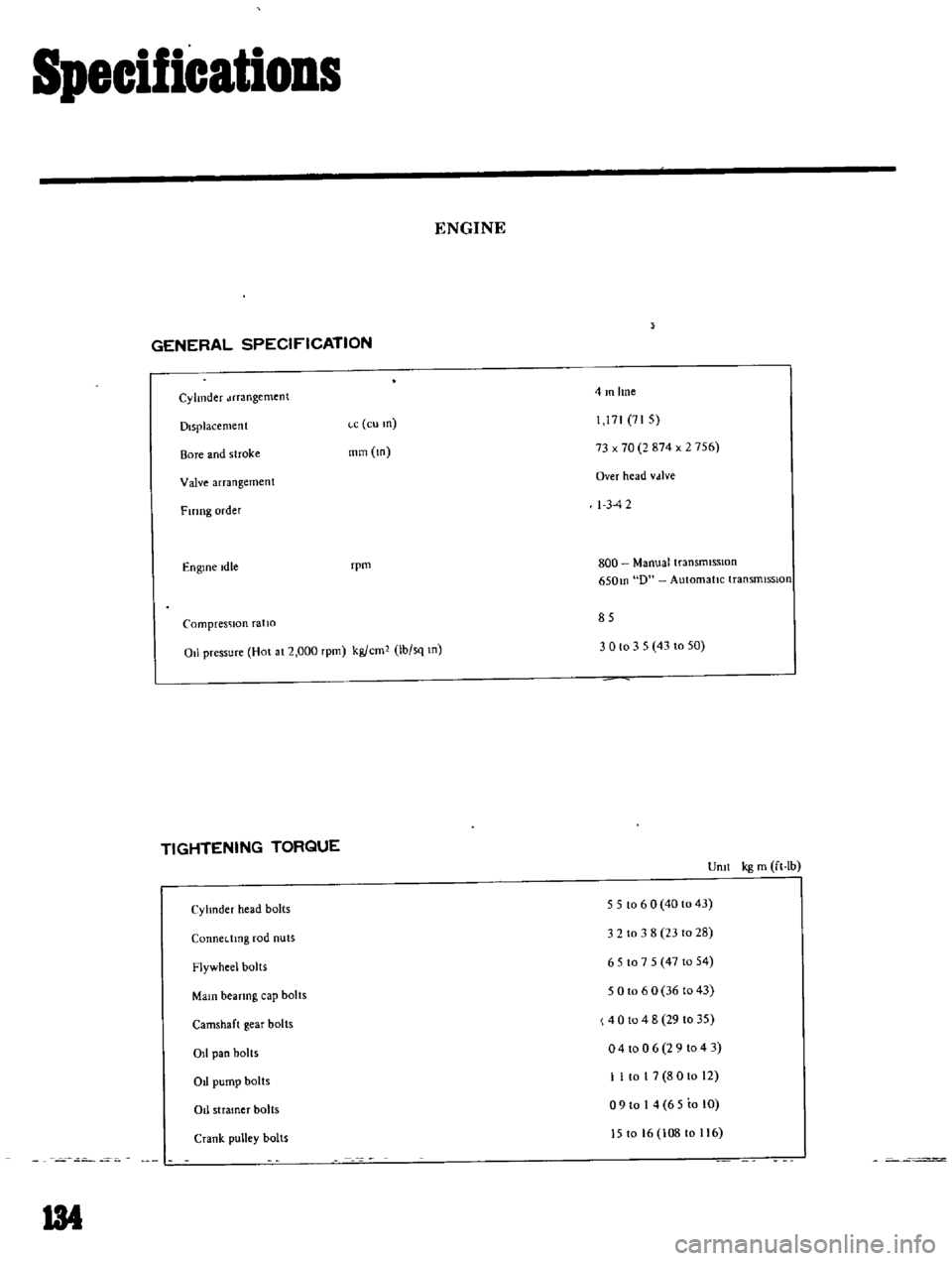
Specifications
ENGINE
GENERAL
SPECIFICATION
Cylinder
Jrrangement
4mlme
Displacement
ce
eu
m
71
71
5
Bore
and
stroke
mm
m
73
x
70
2
874
x
2
756
Valve
arrangement
Over
head
vdlve
Fmng
order
I
3
42
Engine
Idle
rpm
800
Manual
transmiSSIOn
650m
D
Automatic
transrmsslon
Compresc
lon
ratio
85
011
pressure
Hol
al
2
000
rpm
kg
em
Ib
sq
m
3
0
to
3
5
43
10
50
TIGHTENING
TORQUE
Uml
kg
m
ft
Ib
Cyhnder
head
bolts
5
5
10
6
0
40
10
43
3
2
to
3
8
2310
28
CQnnedmg
rod
nuts
Flywheel
bolls
651075
471054
Main
bearing
cap
bolts
5
0
10
6
0
36
to
43
4
0
10
4
8
29
10
35
o
4
to
0
6
2
9
1043
Camshaft
gear
bolts
011
pan
bolts
Ot
pump
bolts
1
I
to
I
7
8
0
10
12
o
9
to
I
4
65
to
lO
J5
to
16
108
to
116
011
stramer
bolts
Crank
pulley
bolts
134