1969 DATSUN B110 brakes
[x] Cancel search: brakesPage 2 of 136
lI
I
DATSUN
1200
RANGE
1971
1973
MAINTENANCE
REPAIR
BY
DRAKE
AUTOMOTIVE
EDITORS
Quick
Referencelodel
MAINTENANCE
TUNE
UP
5
STEERING
89
ENGINEERING
13
REAR
DRIVE
ELECTRICAL
SYSTEM
35
SUSPENSION
93
IGNITION
SYSTEM
43
CLUTCH
99
FUEL
SYSTEM
49
TRANSMISSION
103
COOLING
SYSTEM
63
BODY
WORK
111
BRAKES
67
SPECIFICATIONS
129
FRONT
SUSPENSION
83
The
purpose
of
this
manual
IS
to
provide
the
automobile
owner
and
mechanic
with
a
reference
source
with
which
he
can
perform
normal
service
operations
We
endeavor
to
lOcorporate
the
latest
manufacturing
design
changes
and
up
to
date
specifications
at
the
time
of
publication
While
every
effort
IS
made
to
attain
accuracy
the
Publisher
cannot
be
held
responsible
for
manufacturing
changes
typographical
errors
or
omiSSions
Upon
compIling
the
information
contained
herein
we
have
tried
to
be
brief
and
Simple
relvlng
on
the
combination
of
photographs
Illustrations
and
text
to
make
thIS
manual
a
useful
tool
DRAKE
PUBLISHERS
INC
361
PARK
AVENUE
SOUTH
NEW
YORK
NY
10016
Page 5 of 136
labl8
of
Contents
Jets
60
FRONT
SUSPENSION
TlOuble
Shooting
60
f
DESCRIPTION
RECOMMENDATIONS
TROUBLE
SHOOTING
I
85
COOLING
SYSTEM
DESCRIPTION
64
STEERING
WATER
PUMP
64
Hemoval
65
DESCRIPTION
90
InstallatIOn
65
RECOMMENDATIONS
90
THERMOSTAT
65
TROUBLE
SHOOTING
91
Removal
65
InspectIOn
65
REAR
DRIVE
Installation
65
RADIATOR
66
SUSPENSION
Hemovdl
66
InspectIOn
66
REAR
AXLE
94
InstallatIOn
66
DIFFERENTIAL
94
REAR
SUSPENSION
95
REAR
SHOCK
ABSORBER
96
Replacement
96
BRAKES
InspectIOn
97
RECOMMENDATIONS
97
FRONT
DISC
BRAKE
68
BRAKE
PAD
68
Replacement
68
CLUTCH
InspectIOn
68
ReinstallatIOn
68
DESCRIPTION
CALIPER
70
CLUTCH
PEDAL
Removal
70
Removal
Disassembly
71
InspectIOn
InspectIOn
Repmr
71
ReinstallatIOn
Reassembly
72
Adjustment
ReinstallatIOn
74
CLUTCH
MASTER
CYLINDER
REAR
BRAKE
74
Removal
Hemoval
Dlsdssembly
74
DIsassembly
InspectIOn
75
InspectIOn
Reassembly
ReinstallatIOn
75
Reassembly
HAND
BRAKE
75
RemstallatlOn
Removal
75
BLEEDING
CLUTCH
SYSTEM
InspectIOn
76
RemstallatlOn
77
ADJUSTMENT
78
TRANSMISSION
Front
DI
c
Brake
78
Rear
Brake
78
4
SPEED
TRANSMISSION
Brake
Pedal
HeIght
78
3
SPEED
TRANSMISSION
Hand
Brake
79
TROUBLE
SHOOTING
BLEEPIN
HYD
AULIC
SYs
r
M
79
i
UIQM
ATJ
C
TRANSMJSSIQ
TROUBLE
SHOOTING
80
RECOMMENDATIONS
2
Page 63 of 136

Brakes
Jl
r7
I
J
I
lip
b
Ih
ih
p
lIJ
11
yhndu
blolk
2
Spnn
7
Air
hlu
k
r
12
PI
lon
3
LVI
pm
H
Rl
t
llmll
nn
13
lh
L
prm
hlm
8001
I
YOkl
pnn
5
lIJ
n
ll
prill
111
1
lon
Ii
15
Yoh
Fig
112
Front
diSC
brake
components
Movement
exceeding
the
elastic
dISplacement
IS
released
with
slipping
on
the
seal
surf
a
Returns
elastIC
displacement
of
the
seal
CYLINDER
SIDE
DECOMPRESSION
Fig
113
PIston
seal
automatic
adjusting
operation
FRONT
DISC
BRAKE
I
Brake
pad
2
Retalnl
pin
I
Clip
FIg
114
RemOVing
retaining
pm
Rigidity
of
the
cahper
IS
high
brake
pedal
feehng
IS
adequate
and
the
pad
draggIng
IS
piston
operating
stroke
Increases
shpplng
oc
mlmmlzed
The
padqs
returned
by
elastIcity
curs
on
the
plston
seal
surface
and
thus
of
the
piston
seal
When
the
pad
IS
worn
the
clearance
IS
adjusted
automatIcally
88
Page 64 of 136
r
Brakes
Moreover
In
order
to
prevent
brake
squeahng
a
shIm
IS
Inserted
behind
the
pad
BRAKE
PAD
Replacement
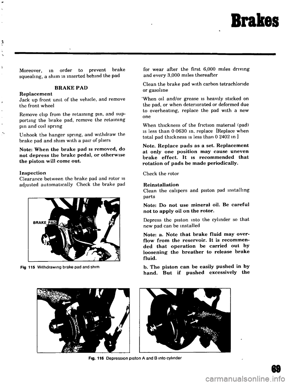
Jack
up
front
UnIt
of
the
vehicle
and
remove
the
front
wheel
Remove
clip
from
the
retaining
pin
and
sup
porting
the
brake
pad
remove
the
retaining
pin
and
COil
spring
Unhook
the
hanger
spring
and
Withdraw
the
brake
pad
and
shim
With
a
pair
of
phers
Note
When
the
brake
pad
IS
removed
do
not
depress
the
brake
pedal
or
otherWise
the
piston
will
come
out
Inspection
Clearance
between
the
brake
pad
and
rotor
IS
adjusted
automatically
Check
the
brake
pad
Fig
115
WIthdraWing
brake
pad
and
shIm
for
wear
after
the
first
6
000
miles
driVing
and
every
3
000
miles
thereafter
Clean
the
brake
pad
With
carbon
tetrachloride
or
gasohne
When
011
and
or
grease
IS
heavIly
stlcked
on
the
pad
or
when
deteriorated
or
deformed
due
to
overheating
replace
the
pad
With
a
new
one
When
thickness
of
the
friction
material
pad
IS
less
than
0
0630
In
replace
Replace
when
total
pad
thIckness
IS
less
than
0
2402
In
Note
Replace
pads
as
a
set
Replacement
at
only
one
position
may
cause
uneven
brake
effect
It
IS
recommended
that
rotation
of
pads
be
made
periodically
Check
the
rotor
Reinstallation
Clean
the
calipers
and
piston
pad
installing
parts
Note
Do
not
use
mineral
oil
Be
careful
not
to
apply
oil
on
the
rotor
Depress
the
pIston
Into
the
cyhnder
so
that
new
pad
can
be
Installed
Note
a
Note
that
brake
fluid
may
over
flow
from
the
reservoir
It
is
recommen
ded
that
operation
be
carried
out
by
loosening
the
breather
to
release
brake
fluid
b
The
piston
can
be
easily
pushed
in
by
hand
But
if
pushed
excessively
the
Fig
116
DepreSSion
piston
A
and
B
Into
cylinder
88
Page 65 of 136
Brakes
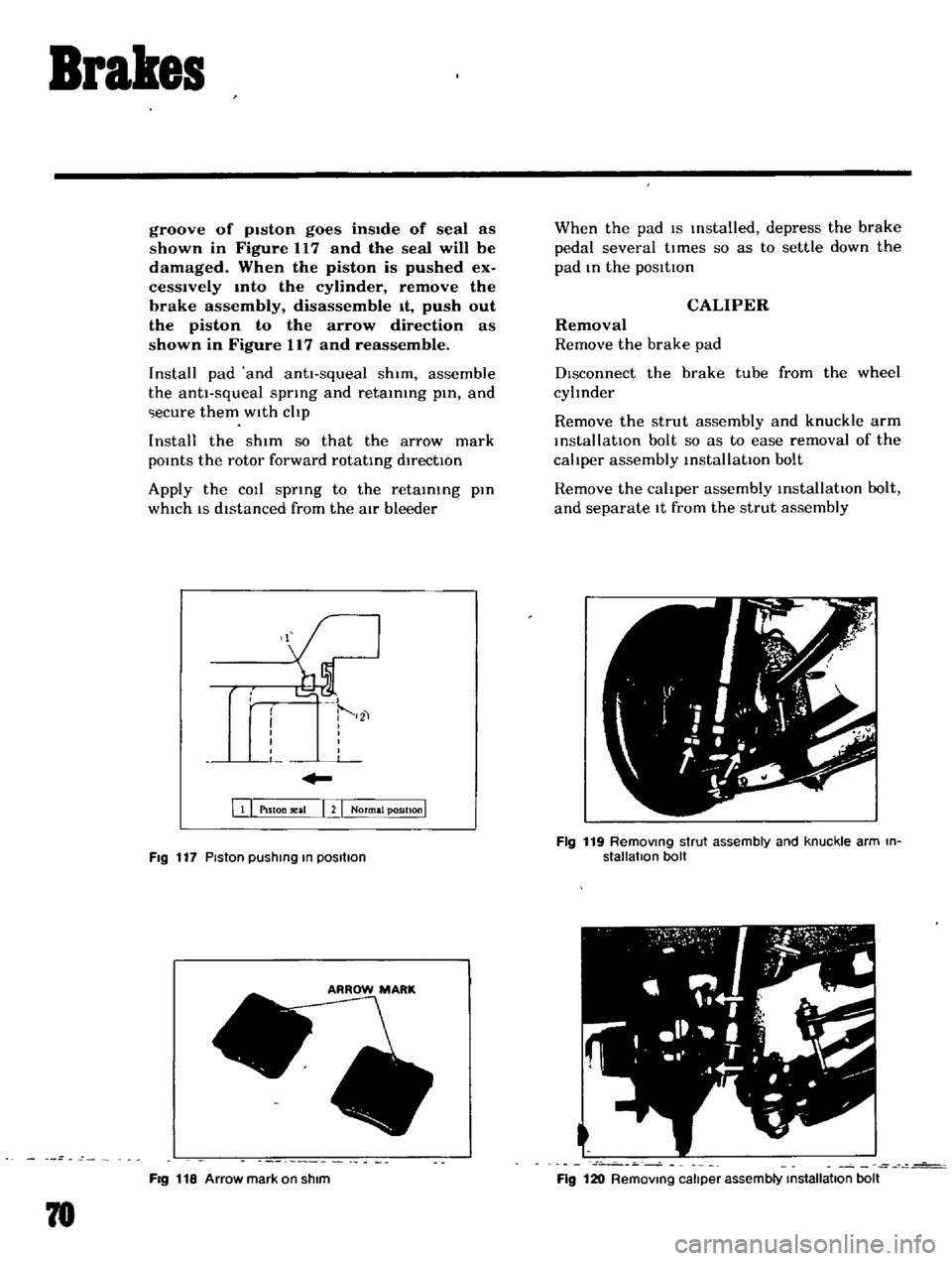
groove
of
pIston
goes
insIde
of
seal
as
shown
in
Figure
117
and
the
seal
will
be
damaged
When
the
piston
is
pushed
ex
cesslvely
mto
the
cylinder
remove
the
brake
assembly
disassemble
It
push
out
the
piston
to
the
arrow
direction
as
shown
in
Figure
117
and
reassemble
Install
pad
and
antt
squeal
shim
assemble
the
anti
squeal
spring
and
retaining
pin
and
ecure
them
with
cltp
Install
the
shim
so
that
the
arrow
mark
pOints
the
rotor
forward
rotating
directIOn
Apply
the
COIl
spring
to
the
retaining
pin
which
IS
distanced
from
the
atr
bleeder
111
PlSton
seal
I
2
I
Normal
position
I
Fig
117
Piston
pushIng
In
posllIon
FIg
118
Arrow
mark
on
shim
78
When
the
pad
IS
Installed
depress
the
brake
pedal
several
tl
mes
so
as
to
settle
down
the
pad
In
the
posltton
CALIPER
Removal
Remove
the
brake
pad
DIsconnect
the
brake
tube
from
the
wheel
cyltnder
Remove
the
strut
assembly
and
knuckle
arm
installatIOn
bolt
so
as
to
ease
removal
of
the
cahper
assembly
installatIOn
bolt
Remove
the
cahper
assembly
installatIOn
bolt
and
separate
It
from
the
strut
assembly
Fig
119
RemOVing
strut
assembly
and
knuckle
arm
in
stallatIon
bolt
Fig
120
RemOVing
caliper
assembly
Installallon
bolt
Page 66 of 136
Brakes
DIsassembly
Remove
mud
and
other
contamInations
from
the
caLiper
as
embly
before
dlsa
sembly
DraIn
bl
ake
fluId
flOm
the
wheel
cylinder
Loosen
the
aIr
bleeder
and
depres
the
pistons
A
and
B
Into
the
cylInder
See
FIg
125
Secure
the
yoke
In
a
vIse
and
tap
the
yoke
head
with
a
hammer
The
cylinder
body
can
then
be
removed
from
the
yoke
When
remOVIng
the
cylinder
body
be
careful
not
to
allow
the
piston
A
comIng
out
from
the
cylIn
der
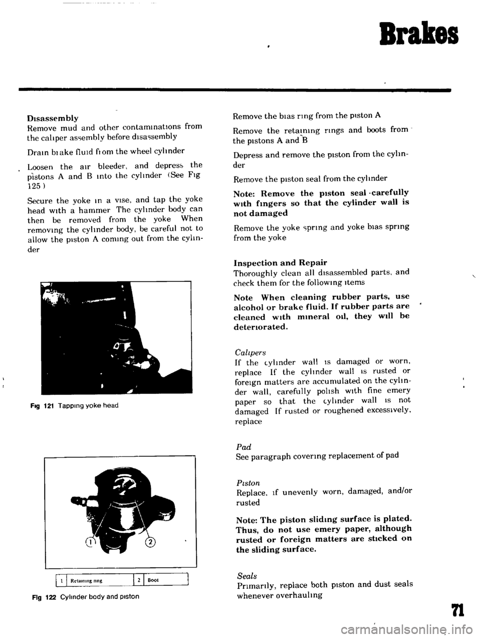
FIg
121
TapPing
yoke
head
5
I
B
Q
Retamlng
nng
J
Boot
Fig
122
Cylinder
body
and
piston
Remove
the
bIas
nng
from
the
piston
A
Remove
the
retaInIng
nngs
and
boots
from
the
pistons
A
and
B
Depress
and
remove
the
piston
from
the
cylin
der
Remove
the
piston
seal
from
the
cylinder
Note
Remove
the
p1ston
seal
carefully
w1th
fmgers
so
that
the
cylinder
wall
is
not
damaged
Remove
the
yoke
prIng
and
yoke
bias
sprIng
from
the
yoke
Inspection
and
Repair
Thoroughly
clean
all
dIsassembled
parts
and
check
them
for
the
follOWIng
Items
Note
When
cleaning
rubber
parts
use
alcohol
or
brake
fluid
If
rubber
parts
are
cleaned
wIth
mmeral
Oil
they
will
be
detenorated
Calzpers
If
the
cylInder
wall
IS
damaged
or
worn
replace
If
the
cylinder
wall
IS
rusted
or
foreIgn
matters
are
accumulated
on
the
cylIn
der
wall
carefully
polIsh
wIth
fine
emery
paper
so
that
the
cylInder
wall
IS
not
damaged
If
rusted
or
roughened
excessively
replace
Pad
See
paragraph
covenng
replacement
of
pad
PIston
Replace
If
unevenly
worn
damaged
and
or
rusted
Note
The
piston
slidmg
surface
is
plated
Thus
do
not
use
emery
paper
although
rusted
or
foreign
matters
are
sttcked
on
the
sliding
surface
Seals
Prlmanly
replace
both
pIston
and
dust
seals
whenever
overhauling
n
Page 67 of 136
Brakes
Note
The
piston
seal
affects
not
only
Ieakmg
but
also
piston
return
For
this
reason
replace
the
piston
seal
even
If
the
damage
IS
minor
Rotor
Check
the
rotor
and
If
It
shows
cOl
e
ex
cesslvely
out
of
round
and
so
forth
recon
ditIOnIng
by
machInIng
l
l
requIred
If
any
ab
normal
condItIOns
such
as
crack
dl
ltortlOn
and
excessIve
deflectIOn
replace
the
rotor
Standard
rotor
thlckne
ls
03740
In
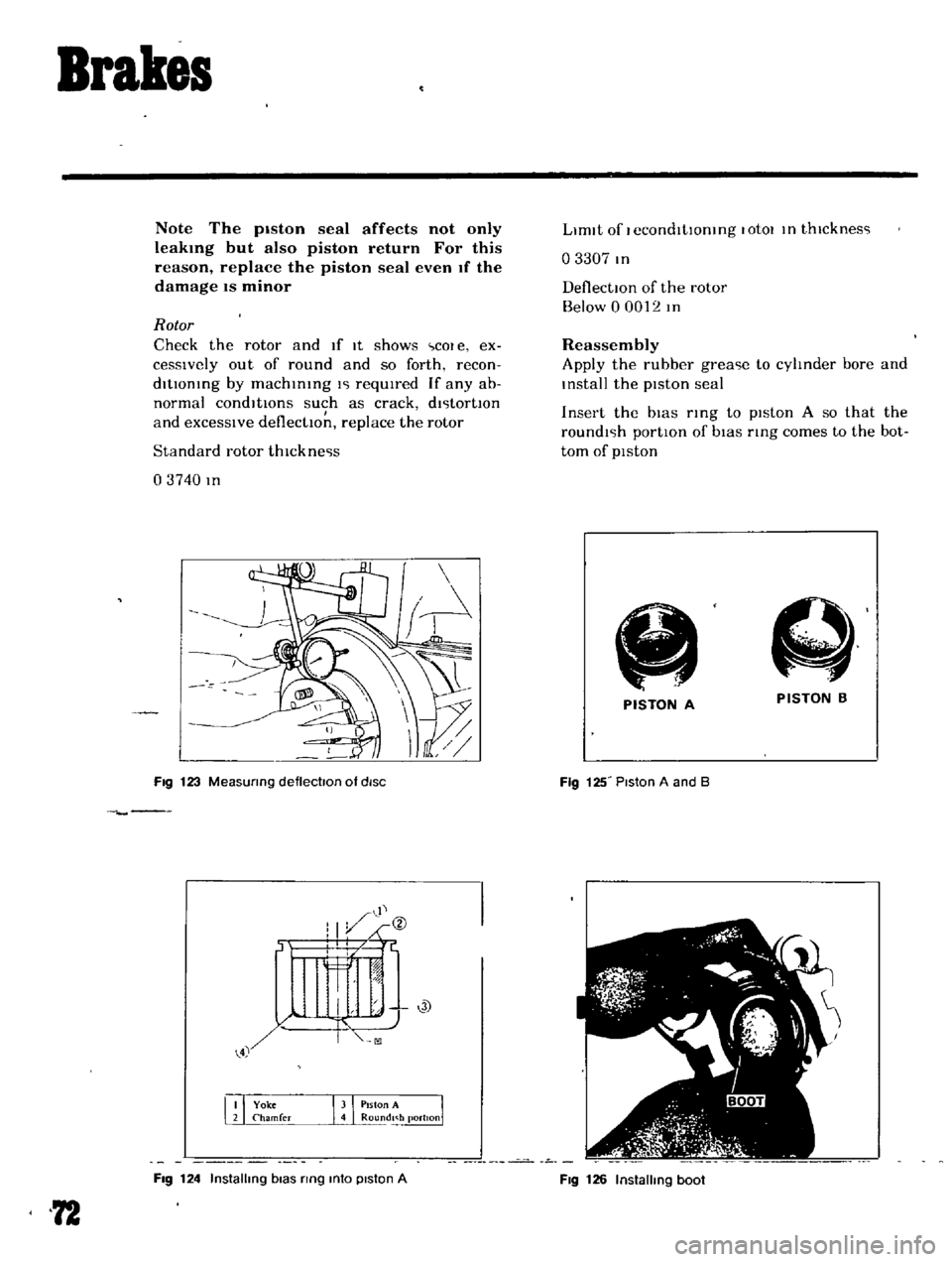
Fig
123
MeaSUring
deflectoon
of
diSC
Fig
124
Installing
bias
ring
mto
piston
A
72
LImIt
of
I
econdltlOntng
lotOl
In
thlcknes
l
o
3307
In
DeflectIOn
of
the
rotor
Below
0
0012
In
Reassembly
Apply
the
rubber
grea
le
to
cylinder
bore
and
Install
the
pIston
seal
Insert
the
bIas
rIng
to
pIston
A
so
that
the
roundl
lh
portIon
of
bIas
ring
comes
to
the
bot
tom
of
pIston
A
PISTON
B
PISTON
A
Fig
125
Piston
A
and
B
Fig
126
Installing
boot
Page 68 of 136
Brakes
Note
Be
careful
not
to
confuse
the
piston
A
with
B
Apply
rubber
grease
hghtly
to
the
shdlng
par
tlon
of
p1ston
and
Insert
the
piston
Into
the
cyhnder
Note
When
insertmg
the
piston
be
careful
not
to
insert
too
far
Install
the
boot
and
retaining
nng
Install
so
that
the
yoke
groove
of
bIas
nng
of
piston
A
COinCide
wIth
the
yoke
groove
of
cyhnder
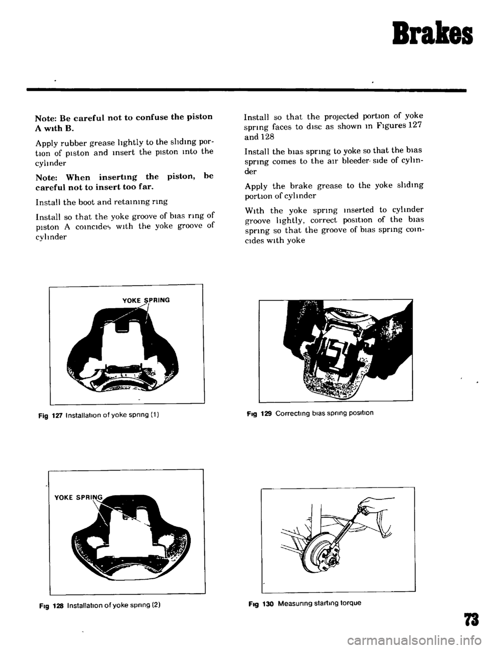
YOKE
SPRING
Fig
127
Installation
of
yoke
spnng
1
Fig
128
InstallatIOn
of
yoke
spnng
2
Install
so
that
the
projected
portIOn
of
yoke
spnng
faces
to
diSC
as
shown
In
Figures
127
and
128
Install
the
bias
spring
to
yoke
so
that
the
bias
spring
comes
to
the
aIr
bleeder
Side
of
cyhn
der
Apply
the
brake
grease
to
the
yoke
shdlng
portIOn
of
cylinder
With
the
yoke
spring
Inserted
to
cylinder
groove
hghtly
correct
poSitIOn
of
the
bias
spnng
so
that
the
groove
of
biaS
spring
COin
Cides
With
yoke
Fig
129
Correctmg
bias
spnng
POSItion
Fig
130
Measunng
startmg
torque
73