1969 DATSUN B110 suspension
[x] Cancel search: suspensionPage 2 of 136
lI
I
DATSUN
1200
RANGE
1971
1973
MAINTENANCE
REPAIR
BY
DRAKE
AUTOMOTIVE
EDITORS
Quick
Referencelodel
MAINTENANCE
TUNE
UP
5
STEERING
89
ENGINEERING
13
REAR
DRIVE
ELECTRICAL
SYSTEM
35
SUSPENSION
93
IGNITION
SYSTEM
43
CLUTCH
99
FUEL
SYSTEM
49
TRANSMISSION
103
COOLING
SYSTEM
63
BODY
WORK
111
BRAKES
67
SPECIFICATIONS
129
FRONT
SUSPENSION
83
The
purpose
of
this
manual
IS
to
provide
the
automobile
owner
and
mechanic
with
a
reference
source
with
which
he
can
perform
normal
service
operations
We
endeavor
to
lOcorporate
the
latest
manufacturing
design
changes
and
up
to
date
specifications
at
the
time
of
publication
While
every
effort
IS
made
to
attain
accuracy
the
Publisher
cannot
be
held
responsible
for
manufacturing
changes
typographical
errors
or
omiSSions
Upon
compIling
the
information
contained
herein
we
have
tried
to
be
brief
and
Simple
relvlng
on
the
combination
of
photographs
Illustrations
and
text
to
make
thIS
manual
a
useful
tool
DRAKE
PUBLISHERS
INC
361
PARK
AVENUE
SOUTH
NEW
YORK
NY
10016
Page 5 of 136
labl8
of
Contents
Jets
60
FRONT
SUSPENSION
TlOuble
Shooting
60
f
DESCRIPTION
RECOMMENDATIONS
TROUBLE
SHOOTING
I
85
COOLING
SYSTEM
DESCRIPTION
64
STEERING
WATER
PUMP
64
Hemoval
65
DESCRIPTION
90
InstallatIOn
65
RECOMMENDATIONS
90
THERMOSTAT
65
TROUBLE
SHOOTING
91
Removal
65
InspectIOn
65
REAR
DRIVE
Installation
65
RADIATOR
66
SUSPENSION
Hemovdl
66
InspectIOn
66
REAR
AXLE
94
InstallatIOn
66
DIFFERENTIAL
94
REAR
SUSPENSION
95
REAR
SHOCK
ABSORBER
96
Replacement
96
BRAKES
InspectIOn
97
RECOMMENDATIONS
97
FRONT
DISC
BRAKE
68
BRAKE
PAD
68
Replacement
68
CLUTCH
InspectIOn
68
ReinstallatIOn
68
DESCRIPTION
CALIPER
70
CLUTCH
PEDAL
Removal
70
Removal
Disassembly
71
InspectIOn
InspectIOn
Repmr
71
ReinstallatIOn
Reassembly
72
Adjustment
ReinstallatIOn
74
CLUTCH
MASTER
CYLINDER
REAR
BRAKE
74
Removal
Hemoval
Dlsdssembly
74
DIsassembly
InspectIOn
75
InspectIOn
Reassembly
ReinstallatIOn
75
Reassembly
HAND
BRAKE
75
RemstallatlOn
Removal
75
BLEEDING
CLUTCH
SYSTEM
InspectIOn
76
RemstallatlOn
77
ADJUSTMENT
78
TRANSMISSION
Front
DI
c
Brake
78
Rear
Brake
78
4
SPEED
TRANSMISSION
Brake
Pedal
HeIght
78
3
SPEED
TRANSMISSION
Hand
Brake
79
TROUBLE
SHOOTING
BLEEPIN
HYD
AULIC
SYs
r
M
79
i
UIQM
ATJ
C
TRANSMJSSIQ
TROUBLE
SHOOTING
80
RECOMMENDATIONS
2
Page 76 of 136
Brakes
Excessive
pedal
travel
All
b
rakes
drag
One
brake
drdgs
Unbalanced
brdkes
Excessive
pedal
pressure
required
poor
brak
es
Brake
chatter
squeak
or
squeal
System
hds
not
been
bled
Improperly
adjusted
clearance
FlUid
level
In
master
cylinder
IS
too
low
Thermal
expansIOn
of
drums
due
to
Qver
hea
lmg
lnsuffiuent
shoe
to
drum
clearance
Weak
shoe
return
springs
Brake
shoe
return
no
free
travel
Seized
master
cylinder
piston
Loose
or
damaged
wheel
bedfmgs
Weak
broken
or
unhooked
brake
shoe
return
spnngs
InsuffiCient
clearance
between
brake
shoe
and
drum
Grease
or
011
on
hnmgs
Seized
piston
In
wheel
cylInder
Tires
Improperly
mtl
lted
Loose
wheel
bearing
Front
suspension
faulty
Grease
mud
or
w
tter
on
Lmmgs
Full
area
of
Immgs
not
Lontaclmg
drums
SLOTed
brake
drums
Dust
on
drums
or
oIl
soLled
Immgs
Weak
shoe
return
springs
Drum
out
of
round
Worn
Itmngs
Bleed
the
system
Adjust
shoe
to
drum
clearance
Full
up
wIth
specIfied
brake
flUId
Bleed
the
system
If
requIred
Allow
drums
to
cool
off
Check
brake
shoe
lImngs
and
drums
Replace
damaged
parts
Adjust
cledrance
Replace
the
spnngs
Adjust
pedal
height
SerVJce
the
master
cyhnder
repla
e
the
pISton
and
bleed
the
syslem
Adjust
Of
replace
wheel
beanngs
Replace
spnng
Adjust
brakes
Clean
brake
mechamsm
repldce
hnmg
and
correct
cause
of
grease
or
011
getllng
on
Lmmg
SerVIce
the
wheel
cyhnder
and
bleed
the
system
Inflate
tires
to
correct
pressure
Adjust
wheel
bearing
Thoroughly
check
and
adlust
all
front
sus
pensIOn
components
Remove
drums
Clean
and
dry
hrongs
or
replace
Replace
shoes
Reface
drums
and
mstall
new
IImngs
Remove
and
clean
drums
thoroughly
ElImmale
oIl
leak
Check
spnngs
and
replace
as
required
Turn
drums
on
lathe
Replace
hrungs
II
Page 78 of 136
pront
Suspension
Qj
@
@
I
Strut
mounting
Insulator
2
Strut
mounllng
bearing
3
Upper
pnng
o
r
at
4
Oumpu
rubblf
5
DU
tlOVU
6
P
ton
rod
7
F
ool
pring
8
Irut
embly
q
Hub
b
t
mbly
10
5pmdh
II
Ball
JOint
12
Trd
nwu
link
1
J
Tln
lon
rod
14
StJblluLr
15
SU
p
mIOn
mlmbt
r
Fig
146
Front
axle
and
suspension
assembly
I
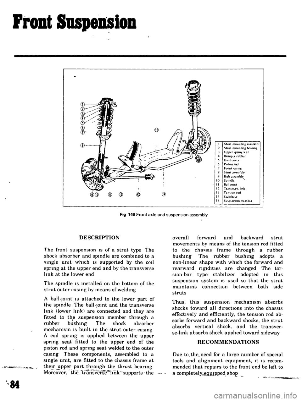
DESCRIPTION
The
front
suspensIOn
IS
of
a
strut
type
The
shock
absorber
and
spIndle
are
combIned
to
a
Ingle
Unit
whIch
IS
supported
by
the
COIl
spnng
at
the
upper
end
and
by
the
transverse
lInk
at
the
lower
end
The
spIndle
IS
Installed
on
the
bottom
of
the
strut
outer
caSIng
by
means
of
weldIng
A
ball
JOInt
IS
attached
to
the
lower
part
of
the
spIndle
The
ball
JOInt
and
the
transverse
lInk
lower
lInk
are
connected
and
they
are
fitted
to
the
suspensIOn
member
through
a
rubber
b
shIng
The
shock
absorber
mechanism
IS
bUIlt
In
the
strut
outer
caSIng
A
COIl
sprIng
IS
apphed
between
the
upper
sprIng
seat
fitted
to
the
upper
end
of
the
piston
rod
and
spring
seat
welded
to
the
outer
caSIng
These
components
assembled
to
a
SIngle
umt
are
fitted
to
the
chaSSIS
frame
at
their
upper
part
through
the
thrust
beanng
M
eover
the
1ransverse
hnk
supports
the
84
overall
forward
and
backward
strut
movements
by
means
of
the
tensIOn
rod
fitted
to
the
cha
sls
frame
through
a
rubber
bushIng
The
rubber
bushIng
adopts
a
non
lInear
shape
WIth
whICh
the
forward
and
rearward
ngldltles
are
changed
The
tor
slOn
bar
type
stabilIzer
adopted
In
thiS
suspensIOn
system
IS
used
so
that
the
strut
maIntaInS
connectIOn
between
both
Side
struts
Thus
thiS
suspensIOn
mechanism
absorbs
shocks
toward
all
directIOns
Into
the
chaSSIS
effectively
and
effiCIently
the
tensIOn
rod
ab
sorbs
forward
and
backward
shocks
the
strut
absorbs
vertical
shock
and
the
transver
se
lInk
absorbs
shock
applIed
toward
SIdeway
RECOMMENDATIONS
Due
to
the
need
for
a
large
number
of
speCial
tools
and
ahgnment
eqUIpment
It
IS
recom
mended
that
repairs
to
the
front
end
be
left
to
a
completely
e
q
pped
shop
Page 79 of 136
Pront
Suspension
j
I
t
4
l
I
i
r
t
I
J
l
I
hf
c
a
j
ll
l
l
11
J
1
f
t
r
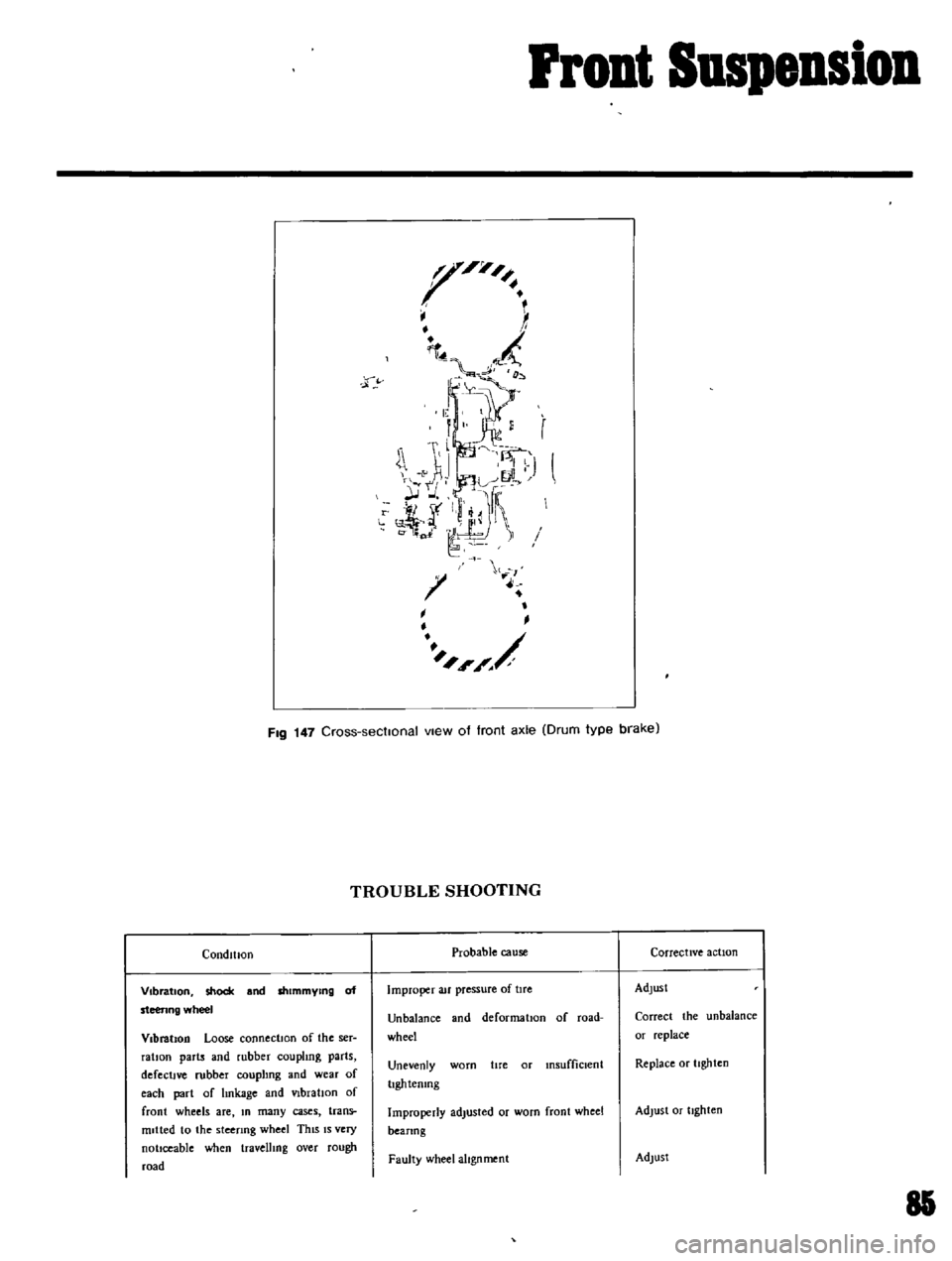
FIg
147
Cross
sectIonal
vIew
of
front
axle
Drum
type
brake
CondltJOn
Vibration
shock
and
shimmYing
of
steenng
wheel
Vibration
Loose
connectIOn
of
the
ser
ratIOn
parts
and
rubber
coupling
parts
defectIve
rubber
couplIng
and
wear
of
each
part
of
hnkage
and
VIbration
of
front
wheels
are
In
many
cases
trans
mitted
to
the
steenng
wheel
ThiS
IS
very
nottceable
when
travellIng
over
rough
road
TROUBLE
SHOOTING
Probable
cause
Improper
au
pressure
of
tIre
Unbalance
and
deformatIon
of
road
wheel
Unevenly
worn
hre
or
insufficient
IIghtemng
Improperly
adlusted
or
worn
front
wheel
beanng
Faulty
wheel
alignment
Corrective
action
Adjust
Correct
the
unbalance
or
replace
Replace
or
ttghten
Adjust
or
tIghten
Adlust
85
Page 80 of 136
Pront
Suspension
Shock
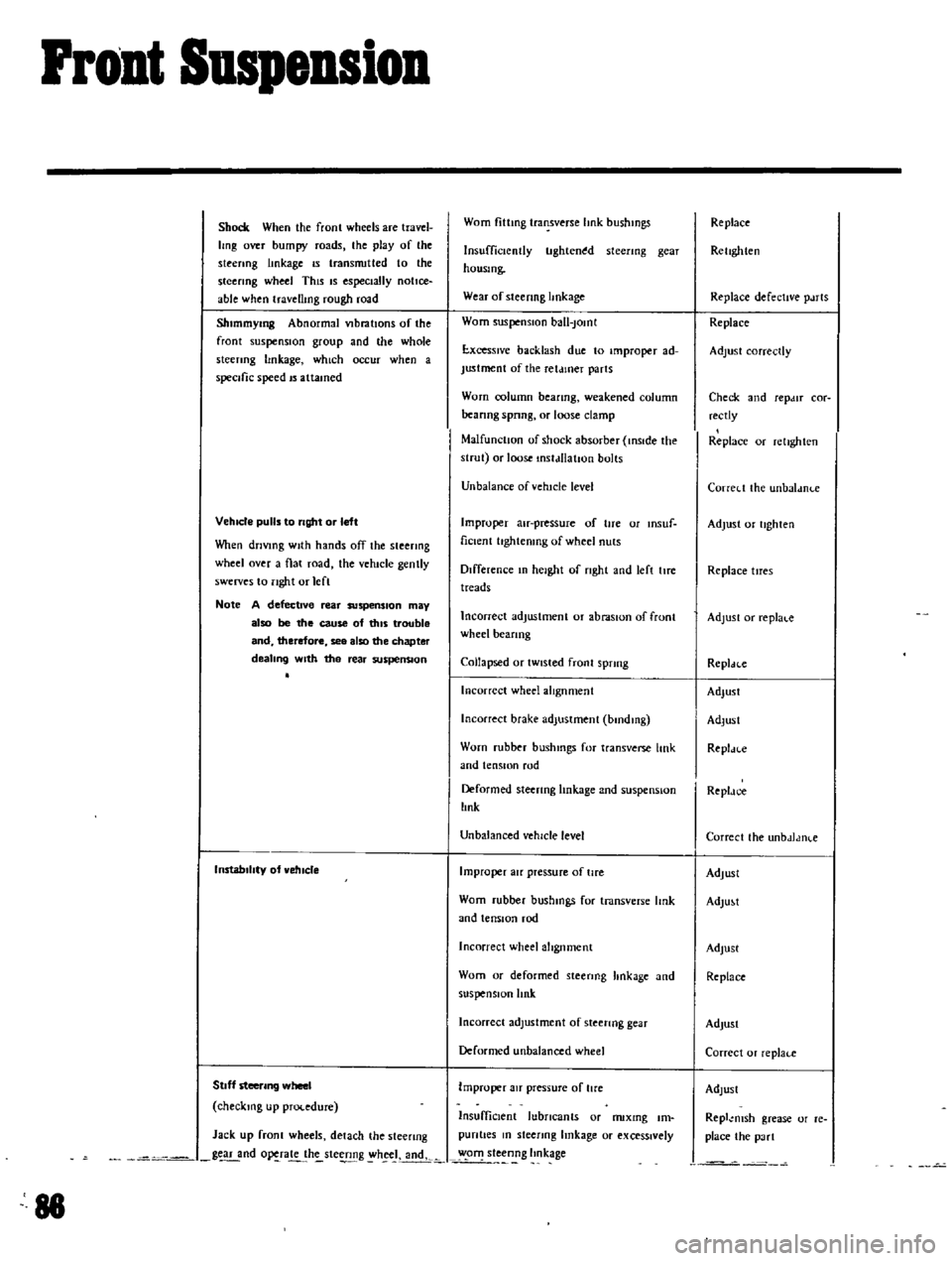
When
the
fronl
wheels
are
travel
Img
over
bumpy
roads
the
play
of
the
steenng
linkage
IS
transnutted
to
the
steering
wheel
This
IS
especially
notice
able
when
travellmg
rough
road
Shlmmymg
Abnormal
VIbratIOns
of
the
front
suspensIOn
group
and
lhe
whole
sleenng
hnkage
which
occur
when
a
specific
speed
IS
attamed
VehIcle
pulls
to
right
or
left
Vhen
driVing
With
hands
off
the
steering
wheel
over
a
flat
road
the
vehicle
gently
swerves
to
nght
or
lefl
Note
A
defective
rear
suspenSion
may
also
be
the
cause
of
tillS
trouble
and
therefore
see
also
the
chapter
dealing
With
the
rear
suspenSion
InstabilIty
of
vehIcle
Stoff
steering
wheel
checking
up
procedure
Jack
up
fronl
wheels
detach
the
steenng
g
nd
o
ra
h
ste
g
h
J
andk
88
Worn
fittmg
transverse
hnk
bushmgs
Insufficiently
tlghten
d
steenng
gear
housmg
Wear
of
steenng
hnkage
Worn
suspensIOn
ball
Jomt
E
xcesslve
backlash
due
to
improper
ad
Justment
of
the
ret
uner
parts
Worn
column
beanng
weakened
column
beanng
spnng
or
loose
clamp
MalfunctIOn
of
shock
absorber
inSIde
the
strut
or
loose
mstdllatJon
bolts
Unbalance
ofvehtcle
level
Improper
au
pressure
of
tire
or
msuf
ficlent
hghtenmg
of
wheel
nuts
Difference
In
height
of
nght
and
left
lIre
treads
Incorrect
adjustment
or
abraSIOn
of
front
wheel
beanng
Collapsed
or
tWisted
front
sprmg
Incorrect
wheel
alIgnment
Incorrect
brake
adjustment
bmdmg
Worn
rubber
bushmgs
for
transverse
link
and
tensIOn
rod
Deformed
steering
linkage
and
suspensIOn
lInk
Unbalanced
vehicle
level
Improper
au
pressure
of
tire
Worn
rubber
bushmgs
for
tmnsverse
Imk
and
tensIOn
rod
Incorrect
wheel
alignment
Worn
or
deformed
steenng
hnkage
and
suspensIOn
link
Incorrect
adjustment
of
steenng
gear
Deformed
unbalanced
wheel
Improper
au
pressure
of
lire
InsuffiCient
lubricants
or
nuxmg
Im
pun
ties
m
sleenng
linkage
or
exceSSively
o
steenng
Imkage
Replace
Rellghten
Replace
defective
p
uts
Replace
Adjust
correctly
Check
and
repdlT
cor
rectly
Replace
or
relighlen
Correl
t
the
unbaldnl
e
Adjust
or
tighten
Replace
tlTes
Adjust
or
replal
c
Repldcc
Adjust
Adlusl
Repl
n
e
Repldc
e
Correcl
the
unbdJdlKe
Adjust
AdlU
t
Adjust
Replace
AdJusl
Correcl
or
replaf
e
Adlust
Repl
msh
grease
or
re
place
the
pa
rt
Page 81 of 136
i
l
Front
SuspeDsion
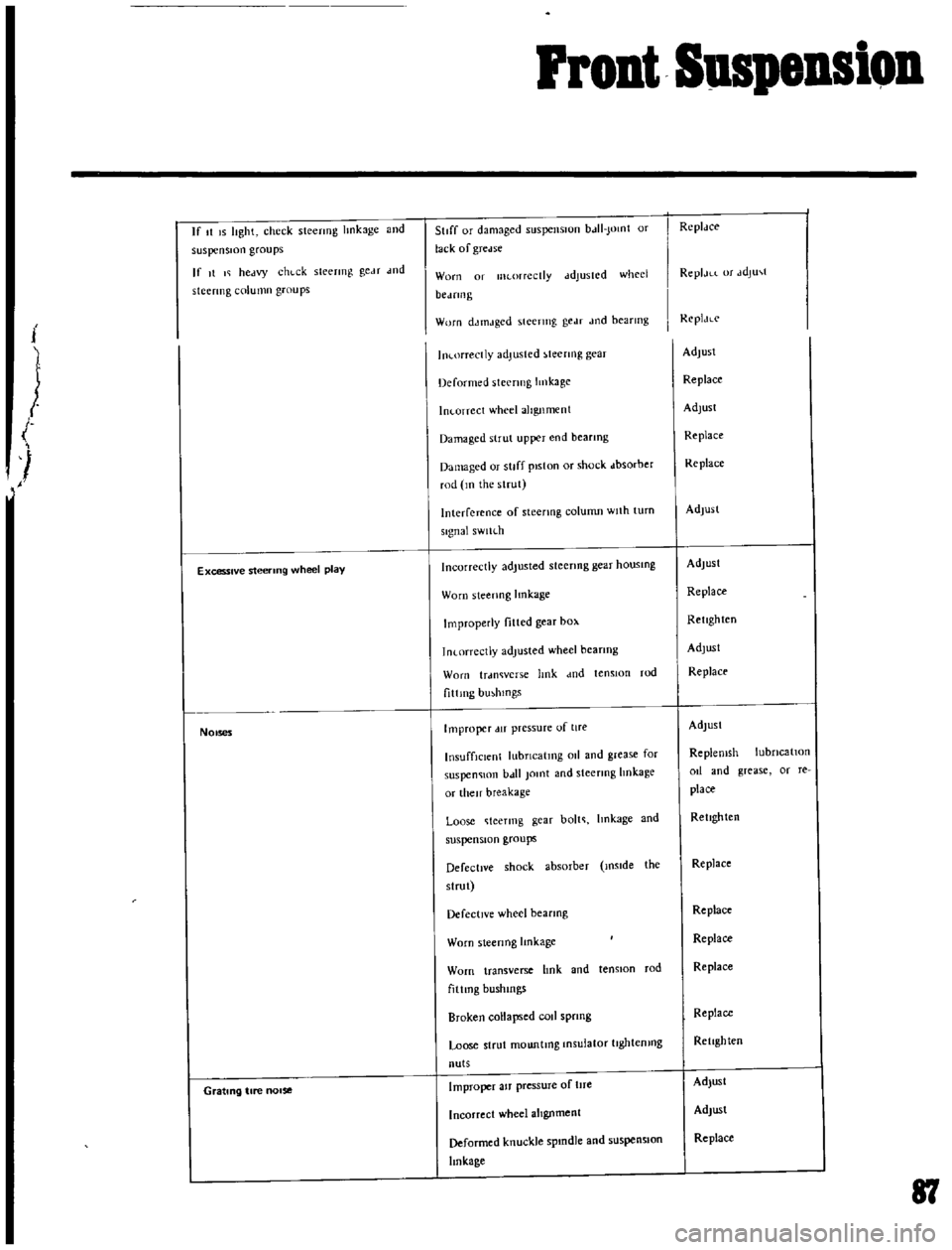
If
t
IS
lIght
check
stecrmg
hnkage
and
suspension
groups
If
It
I
hectvy
chl
ck
sleermg
geM
wd
stcermg
column
groups
Excessive
steering
wheel
play
1
NOises
Grating
tire
nOise
StIff
or
dJmaged
5llspenslUn
bJII
Jomt
or
lack
of
gTcelse
Worn
01
lIKorrcctly
ddJuSICd
whed
bCJfIll
g
Worn
dJtnJged
steering
gedf
Jod
bearmg
In
orrectly
adjusted
teenng
gear
Deformed
steering
Imkage
In
orrcct
wheel
alignment
Damaged
strut
upper
end
bearmg
Damaged
or
stiff
piston
or
shock
dbsorber
rod
m
the
strut
Interference
of
steenng
column
Wllh
turn
signal
sWlh
h
Incorrectly
adjusted
steenng
gear
housmg
Worn
steenng
lmkage
Improperly
fitted
gear
box
1n
orrectJy
adjusted
wheel
bearIng
Worn
trdl1Wcrs
e
hnk
dnd
tensIOn
rod
f1ttlllg
bmhlOgs
Improper
lIT
pressure
of
lire
InsuffiCient
lubncatmg
011
and
grease
for
suspen
lOn
b
t11
Jomt
and
steermg
hnkage
or
then
breakage
Loose
teermg
gear
bolt
Imkage
and
suspension
groups
Defective
shock
absorber
mslde
the
slrut
Defective
wheel
bearmg
Worn
sleenng
Imkage
Worn
transverse
hnk
and
tenston
rod
fiUmg
bushmgs
Broken
collapsed
rod
sprmg
Loose
strut
mountmg
Insulator
tJghtemng
nuts
Improper
aJf
pressure
of
tlfe
Incorrect
wheel
alIgnment
Deformed
knuckle
spmdle
and
suspensIOn
linkage
RcplJce
ReplJLL
or
JdJu
t
ReplJLc
AdJusl
Replace
Adlust
Replace
Replace
Adlusl
Adjust
Replace
Retighten
Adjust
Replace
Adlusl
Replemsh
lubncatlOn
od
and
grease
or
re
place
Retighten
Replace
Replace
Replace
Replace
Replace
Retighten
Adjust
Adjust
Replace
81
Page 82 of 136
Front
Suspension
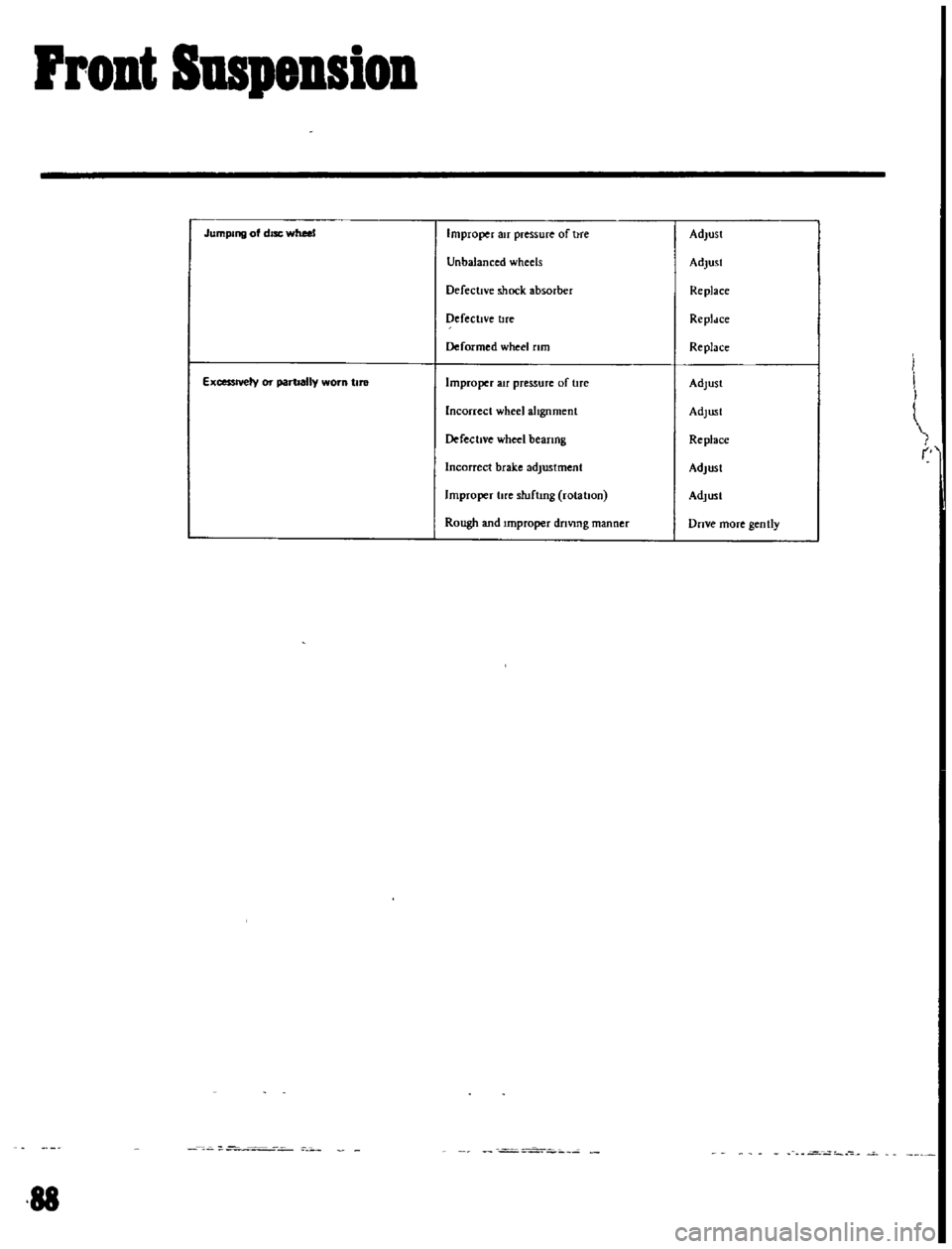
Jumping
of
disc
wheel
Improper
air
pressure
of
hre
Adjust
Unbalanced
wheels
Adjust
Defective
shock
absorber
Replace
DefectIve
tlfe
Repldce
Deformed
wheel
rim
Replace
ExcessIVely
or
partially
worn
tIre
Improper
au
pressure
of
tlfe
Adlust
Incorrect
wheel
alIgnment
Adlusl
DefectIVe
wheel
beanng
Replace
Incorrect
brake
adjustment
Adjust
Improper
lire
sluflmg
rolahon
Adlusl
Rough
and
Improper
driVing
manner
Dnve
more
gen
tly
I
88