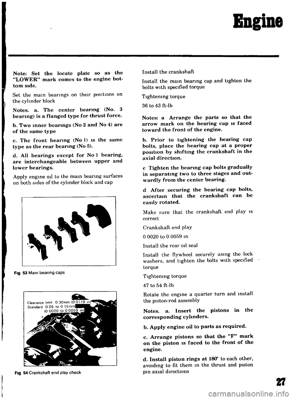
1969 DATSUN B110 oil change
[x] Cancel search: oil changePage 9 of 136

aintenIDce
une
up
Find
the
cause
for
necessary
corrective
action
b
Oil
with
extremely
low
viscosity
in
dicates
dllutton
with
gasoline
Check
011
level
If
found
below
L
mark
refill
to
H
mark
on
gauge
OIL
FILTER
The
011
filter
IS
of
a
cartndge
type
Check
for
011
leaks
through
gasketed
flange
If
any
leakage
IS
found
retIghten
shghtly
If
nece
sary
replaLe
filter
as
an
assembly
When
mstalhng
an
011
filter
tIghten
by
hand
Note
Do
not
overtighten
011
fIlter
or
oil
leakage
may
result
I
I
Fig
3
Checking
engine
011
level
Oc
OF
I
0
121
20141
30
21
401401
5015BI
I
EGOQl
I
10
20
Fig
4
Protection
concentration
COOLANT
L
L
C
IS
al
ethylene
glycol
base
product
con
tammg
chemical
mhlbltors
to
protect
the
coohng
system
from
rustmg
and
corrosIOn
The
L
I
C
does
not
con
tam
any
glycerme
ethyl
or
methyl
alcohol
It
wIll
not
evaporate
or
bOll
away
and
can
be
used
wIth
either
high
or
low
temperature
thermostat
It
flows
freely
transfers
heat
effiCiently
and
will
not
clog
the
passages
m
the
coohng
system
The
L
L
C
must
not
be
mIxed
wIth
other
products
ThiS
coolant
can
be
used
throughout
the
seasons
of
the
year
Whenever
any
coolant
IS
changed
the
coohng
system
should
be
flushed
and
refilled
wIth
a
new
coolant
Check
the
level
COMPRESSION
Compression
pressure
test
Note
To
test
cylinder
compression
remove
all
spark
plugs
and
hold
tester
fit
Percent
BOllIng
pomt
concen
09
kg
cm2
Freeze
tra
lion
Sea
level
coolmg
sys
protectIon
tern
pressure
30
2210F
2550F
50f
50
2280
F
2610F
31oF
ETO
104
Fig
5
Testing
compressIon
pressure
7
Page 27 of 136

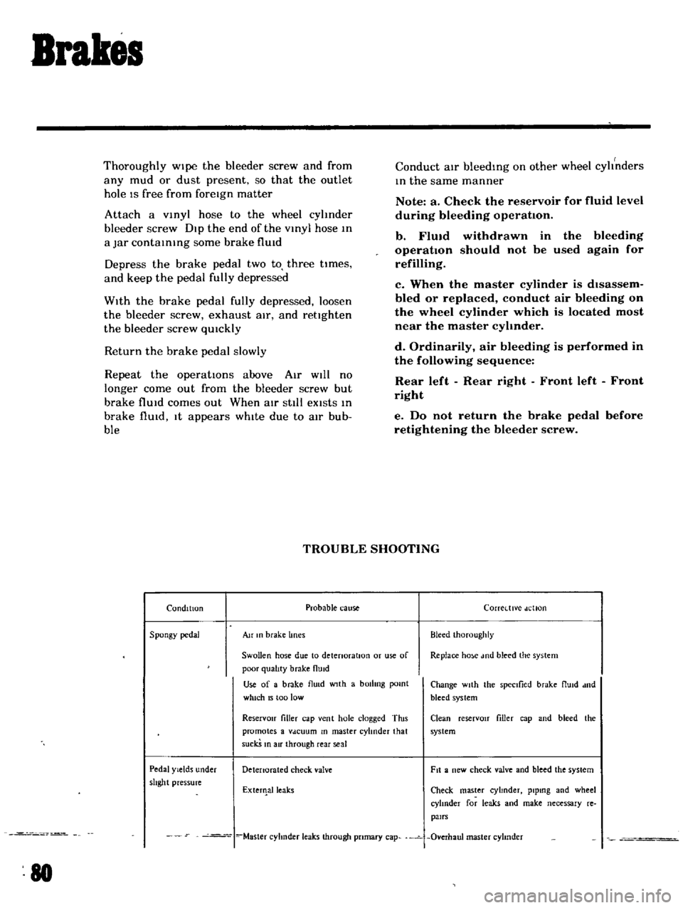
Bogine
Note
Set
the
locate
plate
so
as
the
LOWER
mark
comes
to
the
engine
bot
tom
side
Set
the
maIn
bearIngR
on
theIr
posItIOns
on
the
cylinder
block
Notes
a
The
center
bearmg
No
3
bearmg
is
a
flanged
type
for
thrust
force
b
Two
lOner
bearmgs
No
2
and
No
4
are
of
the
same
type
c
The
front
bearmg
No
1
IS
the
same
type
as
the
rear
bearmg
No
5
d
All
bearings
except
for
No
I
bearing
are
interchangeable
between
upper
and
lower
bearings
Apply
engIne
OIl
to
the
mam
bearIng
surfaces
on
both
sIdes
of
the
cyltnder
block
and
cap
Fig
53
Mam
bearing
caps
Fig
54
Crankshaft
end
play
check
Install
the
crankshaft
Install
the
mam
bearmg
cap
and
tighten
the
bolts
with
specified
torque
Tlghtemng
torque
36
to
43
ft
Ib
Notes
a
Arrange
the
parts
so
that
the
arrow
mark
on
the
bearing
cap
IS
faced
toward
the
front
of
the
engine
b
Prior
to
tightening
the
bearing
cap
bolts
place
the
bearing
cap
at
a
proper
posItIon
by
shlftmg
the
crankshaft
in
the
axial
direction
c
Tighten
the
bearmg
cap
bolts
gradually
in
separatmg
two
to
three
stages
and
out
wardly
from
the
center
bearing
d
After
securing
the
bearing
cap
bolts
ascertam
that
the
crankshaft
can
be
easily
rotated
Make
sure
that
the
crankshaft
end
play
IS
correct
Crankshaft
end
play
o
0020
to
0
0059
In
I
nstalI
the
rear
011
seal
Install
the
flywheel
securely
USIng
the
lock
washers
and
tighten
the
bolts
with
specIfied
torque
Tlghtemng
torque
47
to
54
ft
Ib
Rotate
the
engine
a
quarter
turn
and
mstall
the
piston
rod
assembly
Notes
a
Insert
the
pistons
in
the
corresponding
cyhnders
b
Apply
engine
oil
to
parts
as
required
c
Arrange
pistons
so
that
the
F
mark
on
the
piston
IS
faced
to
the
front
of
the
engine
d
Install
piston
rings
at
18
Y
to
each
other
avoIdIng
to
fit
them
In
the
thrust
and
pIston
pIn
aXial
directIOns
27
Page 75 of 136

Brakes
Thoroughly
Wipe
the
bleeder
screw
and
from
any
mud
or
dust
present
so
that
the
outlet
hole
IS
free
from
foreign
matter
Attach
a
VInyl
hose
to
the
wheel
cyhnder
bleeder
screw
Dip
the
end
of
the
VInyl
hose
In
a
Jar
contaInIng
some
brake
flUId
Depress
the
brake
pedal
two
to
three
times
and
keep
the
pedal
fully
depressed
With
the
brake
pedal
fully
depressed
loosen
the
bleeder
screw
exhaust
air
and
rettghten
the
bleeder
screw
qUIckly
Return
the
brake
pedal
slowly
Repeat
the
operatIons
above
Air
WIll
no
longer
come
out
from
the
bleeder
screw
but
brake
flUId
comes
out
When
atr
stIll
eXists
In
brake
flUId
It
appears
whIte
due
to
aIr
bub
ble
Conduct
aIr
bleedIng
on
other
wheel
cyhnders
In
the
same
manner
Note
a
Check
the
reservoir
for
fluid
level
during
bleeding
operation
b
FlUid
withdrawn
in
the
operation
should
not
be
used
refilling
bleeding
again
for
c
When
the
master
cylinder
is
dIsassem
bled
or
replaced
conduct
air
bleeding
on
the
wheel
cylinder
which
is
located
most
near
the
master
cyhnder
d
Ordinarily
air
bleeding
is
performed
in
the
following
sequence
Rear
left
Rear
right
Front
left
Front
right
e
Do
not
return
the
brake
pedal
before
retightening
the
bleeder
screw
TROUBLE
SHOOTING
Condition
Probable
cause
Corretttve
dellon
Spongy
pedal
Au
In
brake
lines
Bleed
Ihoroughly
Swollen
hose
due
to
detenoratlOn
or
use
of
Replace
ho
e
md
bleed
the
system
poor
qualIty
brake
flUid
Use
of
a
brake
flu
d
wIth
a
bOilIng
pomt
Change
wIth
the
spectlied
brake
flUId
dnd
which
15
too
low
bleed
system
ReservOir
filler
cap
vent
hole
clogged
Tins
Clean
reserVOIr
filler
cap
and
bleed
the
promotes
a
Vdcuum
In
master
cylinder
that
system
suckS
In
air
through
rear
seal
Pedal
Yields
under
Detenorated
check
valve
Fit
a
new
check
valve
and
bleed
the
system
shght
pressure
ExterIlalleaks
Check
master
cyhnder
plpmg
and
wheel
cylInder
for
leaks
and
make
necessary
re
pairs
Master
cyhnder
leaks
through
pnmary
cap
Overhaul
master
cyhnder
80
Page 78 of 136

pront
Suspension
Qj
@
@
I
Strut
mounting
Insulator
2
Strut
mounllng
bearing
3
Upper
pnng
o
r
at
4
Oumpu
rubblf
5
DU
tlOVU
6
P
ton
rod
7
F
ool
pring
8
Irut
embly
q
Hub
b
t
mbly
10
5pmdh
II
Ball
JOint
12
Trd
nwu
link
1
J
Tln
lon
rod
14
StJblluLr
15
SU
p
mIOn
mlmbt
r
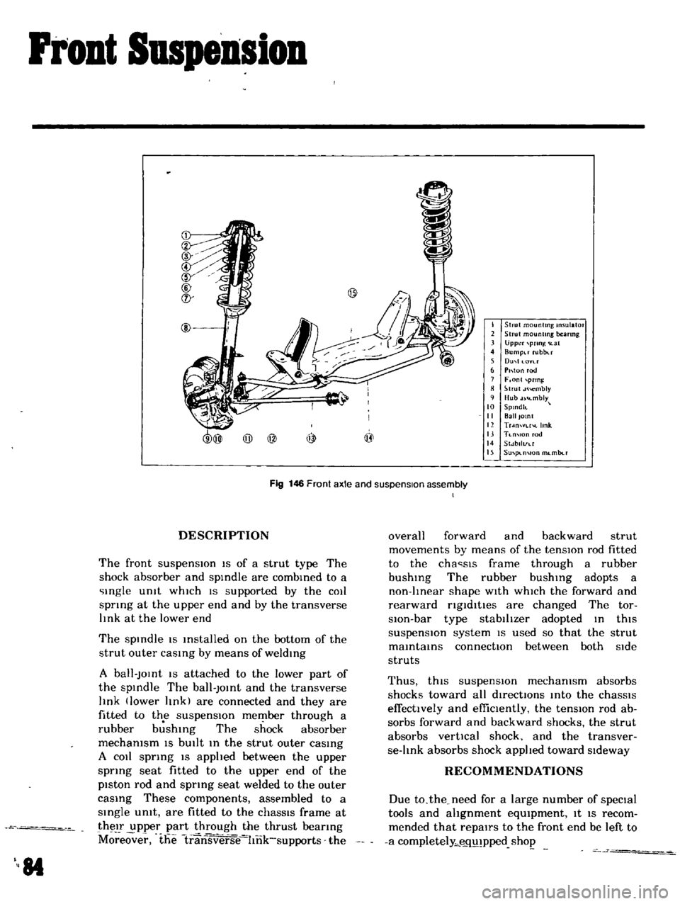
Fig
146
Front
axle
and
suspension
assembly
I
DESCRIPTION
The
front
suspensIOn
IS
of
a
strut
type
The
shock
absorber
and
spIndle
are
combIned
to
a
Ingle
Unit
whIch
IS
supported
by
the
COIl
spnng
at
the
upper
end
and
by
the
transverse
lInk
at
the
lower
end
The
spIndle
IS
Installed
on
the
bottom
of
the
strut
outer
caSIng
by
means
of
weldIng
A
ball
JOInt
IS
attached
to
the
lower
part
of
the
spIndle
The
ball
JOInt
and
the
transverse
lInk
lower
lInk
are
connected
and
they
are
fitted
to
the
suspensIOn
member
through
a
rubber
b
shIng
The
shock
absorber
mechanism
IS
bUIlt
In
the
strut
outer
caSIng
A
COIl
sprIng
IS
apphed
between
the
upper
sprIng
seat
fitted
to
the
upper
end
of
the
piston
rod
and
spring
seat
welded
to
the
outer
caSIng
These
components
assembled
to
a
SIngle
umt
are
fitted
to
the
chaSSIS
frame
at
their
upper
part
through
the
thrust
beanng
M
eover
the
1ransverse
hnk
supports
the
84
overall
forward
and
backward
strut
movements
by
means
of
the
tensIOn
rod
fitted
to
the
cha
sls
frame
through
a
rubber
bushIng
The
rubber
bushIng
adopts
a
non
lInear
shape
WIth
whICh
the
forward
and
rearward
ngldltles
are
changed
The
tor
slOn
bar
type
stabilIzer
adopted
In
thiS
suspensIOn
system
IS
used
so
that
the
strut
maIntaInS
connectIOn
between
both
Side
struts
Thus
thiS
suspensIOn
mechanism
absorbs
shocks
toward
all
directIOns
Into
the
chaSSIS
effectively
and
effiCIently
the
tensIOn
rod
ab
sorbs
forward
and
backward
shocks
the
strut
absorbs
vertical
shock
and
the
transver
se
lInk
absorbs
shock
applIed
toward
SIdeway
RECOMMENDATIONS
Due
to
the
need
for
a
large
number
of
speCial
tools
and
ahgnment
eqUIpment
It
IS
recom
mended
that
repairs
to
the
front
end
be
left
to
a
completely
e
q
pped
shop