1969 DATSUN B110 brake fluid
[x] Cancel search: brake fluidPage 64 of 136
r
Brakes
Moreover
In
order
to
prevent
brake
squeahng
a
shIm
IS
Inserted
behind
the
pad
BRAKE
PAD
Replacement
Jack
up
front
UnIt
of
the
vehicle
and
remove
the
front
wheel
Remove
clip
from
the
retaining
pin
and
sup
porting
the
brake
pad
remove
the
retaining
pin
and
COil
spring
Unhook
the
hanger
spring
and
Withdraw
the
brake
pad
and
shim
With
a
pair
of
phers
Note
When
the
brake
pad
IS
removed
do
not
depress
the
brake
pedal
or
otherWise
the
piston
will
come
out
Inspection
Clearance
between
the
brake
pad
and
rotor
IS
adjusted
automatically
Check
the
brake
pad
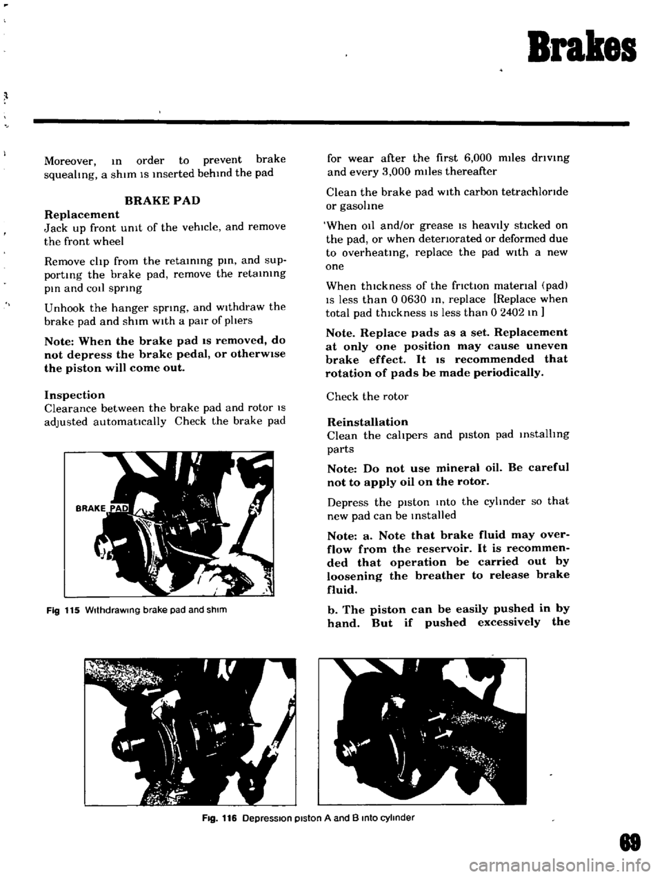
Fig
115
WIthdraWing
brake
pad
and
shIm
for
wear
after
the
first
6
000
miles
driVing
and
every
3
000
miles
thereafter
Clean
the
brake
pad
With
carbon
tetrachloride
or
gasohne
When
011
and
or
grease
IS
heavIly
stlcked
on
the
pad
or
when
deteriorated
or
deformed
due
to
overheating
replace
the
pad
With
a
new
one
When
thickness
of
the
friction
material
pad
IS
less
than
0
0630
In
replace
Replace
when
total
pad
thIckness
IS
less
than
0
2402
In
Note
Replace
pads
as
a
set
Replacement
at
only
one
position
may
cause
uneven
brake
effect
It
IS
recommended
that
rotation
of
pads
be
made
periodically
Check
the
rotor
Reinstallation
Clean
the
calipers
and
piston
pad
installing
parts
Note
Do
not
use
mineral
oil
Be
careful
not
to
apply
oil
on
the
rotor
Depress
the
pIston
Into
the
cyhnder
so
that
new
pad
can
be
Installed
Note
a
Note
that
brake
fluid
may
over
flow
from
the
reservoir
It
is
recommen
ded
that
operation
be
carried
out
by
loosening
the
breather
to
release
brake
fluid
b
The
piston
can
be
easily
pushed
in
by
hand
But
if
pushed
excessively
the
Fig
116
DepreSSion
piston
A
and
B
Into
cylinder
88
Page 66 of 136
Brakes
DIsassembly
Remove
mud
and
other
contamInations
from
the
caLiper
as
embly
before
dlsa
sembly
DraIn
bl
ake
fluId
flOm
the
wheel
cylinder
Loosen
the
aIr
bleeder
and
depres
the
pistons
A
and
B
Into
the
cylInder
See
FIg
125
Secure
the
yoke
In
a
vIse
and
tap
the
yoke
head
with
a
hammer
The
cylinder
body
can
then
be
removed
from
the
yoke
When
remOVIng
the
cylinder
body
be
careful
not
to
allow
the
piston
A
comIng
out
from
the
cylIn
der
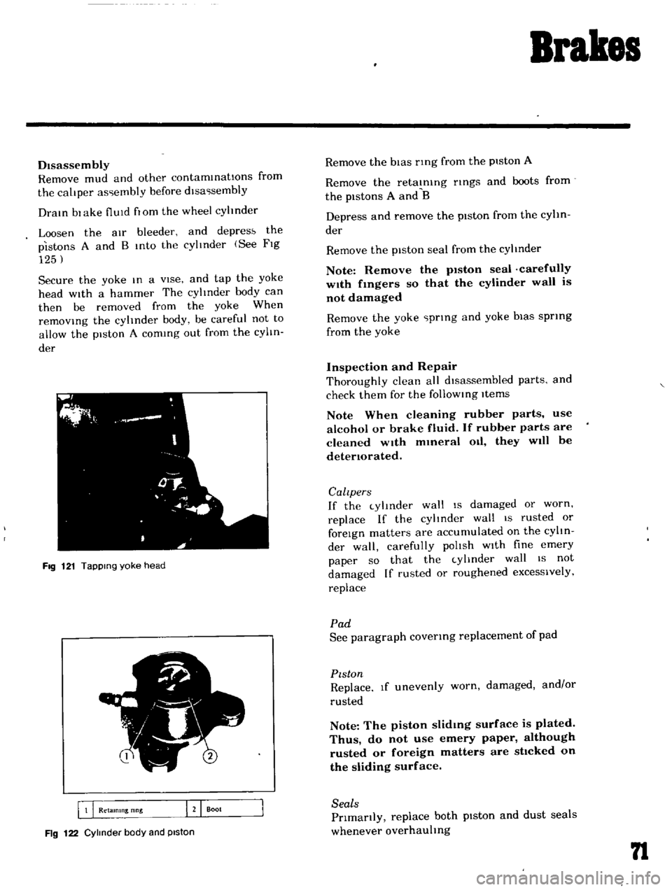
FIg
121
TapPing
yoke
head
5
I
B
Q
Retamlng
nng
J
Boot
Fig
122
Cylinder
body
and
piston
Remove
the
bIas
nng
from
the
piston
A
Remove
the
retaInIng
nngs
and
boots
from
the
pistons
A
and
B
Depress
and
remove
the
piston
from
the
cylin
der
Remove
the
piston
seal
from
the
cylinder
Note
Remove
the
p1ston
seal
carefully
w1th
fmgers
so
that
the
cylinder
wall
is
not
damaged
Remove
the
yoke
prIng
and
yoke
bias
sprIng
from
the
yoke
Inspection
and
Repair
Thoroughly
clean
all
dIsassembled
parts
and
check
them
for
the
follOWIng
Items
Note
When
cleaning
rubber
parts
use
alcohol
or
brake
fluid
If
rubber
parts
are
cleaned
wIth
mmeral
Oil
they
will
be
detenorated
Calzpers
If
the
cylInder
wall
IS
damaged
or
worn
replace
If
the
cylinder
wall
IS
rusted
or
foreIgn
matters
are
accumulated
on
the
cylIn
der
wall
carefully
polIsh
wIth
fine
emery
paper
so
that
the
cylInder
wall
IS
not
damaged
If
rusted
or
roughened
excessively
replace
Pad
See
paragraph
covenng
replacement
of
pad
PIston
Replace
If
unevenly
worn
damaged
and
or
rusted
Note
The
piston
slidmg
surface
is
plated
Thus
do
not
use
emery
paper
although
rusted
or
foreign
matters
are
sttcked
on
the
sliding
surface
Seals
Prlmanly
replace
both
pIston
and
dust
seals
whenever
overhauling
n
Page 74 of 136
Brakes
Adjusting
shIm
thickness
for
selectIOn
o
0197
In
00315
In
o
0630
In
Note
When
adjusting
be
sure
to
use
ad
Jusbng
sh1ms
having
same
th1ckness
for
upper
and
lower
brake
master
cylinder
IOstallahon
bolts
Upon
completIOn
of
adjusting
shIm
adjust
ment
tighten
the
stopper
down
to
such
an
ex
tent
that
heIght
of
the
pedal
head
IS
5
57
pO
0787
In
and
tighten
the
lock
nut
becurely
Free
travel
of
the
brake
pedal
IS
0
197
to
0591
tn
and
the
stroke
IS
4
72
In
Hand
Brake
Turn
the
turn
buckle
properly
and
adjust
hand
brake
lever
operatmg
stroke
correctly
so
that
operatmg
stroke
IS
3
091
m
16
notches
at
operatIng
force
of
243
to
331
Ib
Upon
com
pletIOn
of
adjustment
be
sure
to
tIghten
the
lock
nut
Upon
completIOn
of
the
adjustment
release
the
hand
brake
lever
and
make
sure
that
the
rear
wheels
are
not
braked
Normal
btroke
3091
In
6
notches
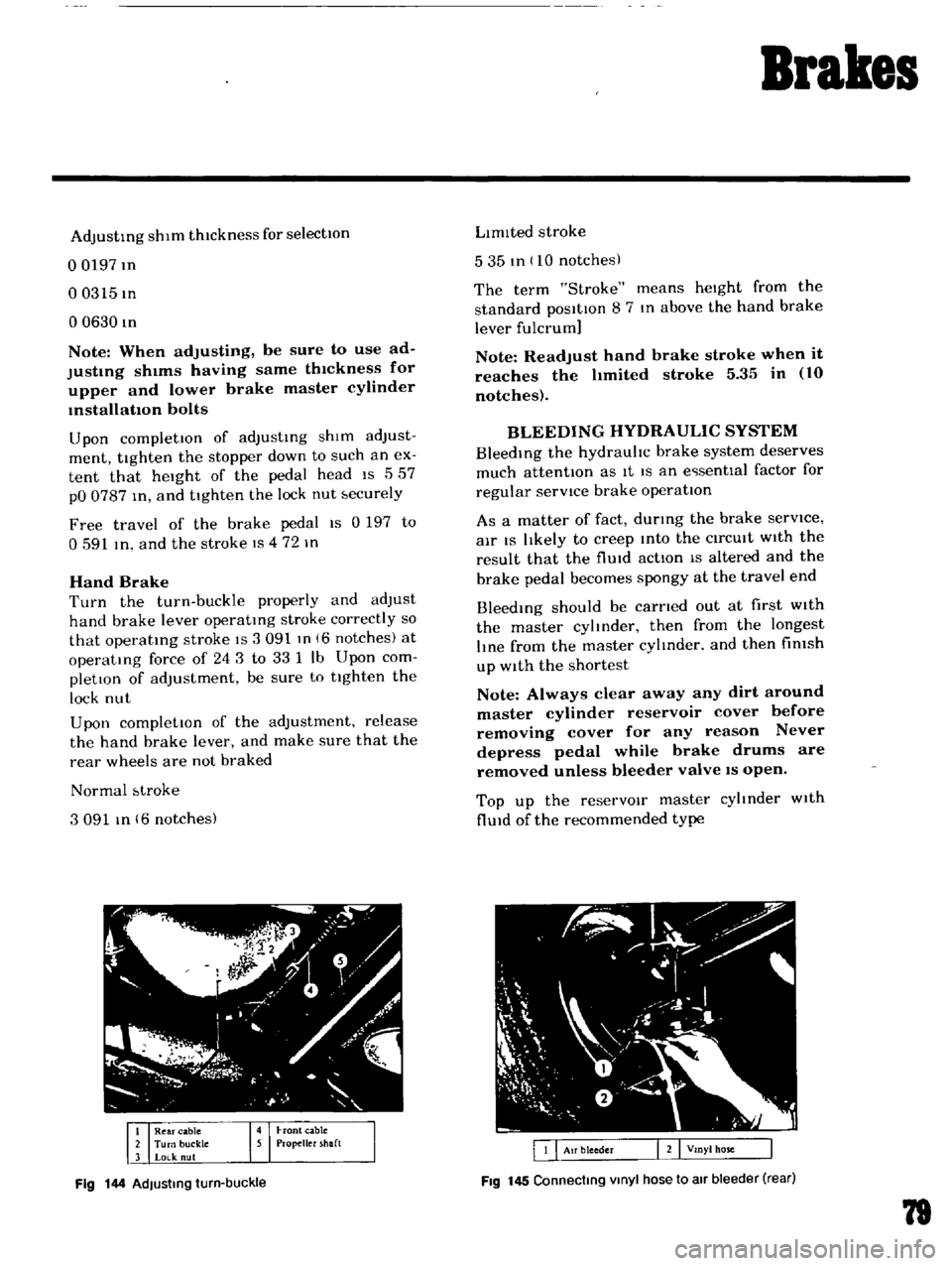
Fig
144
AdJusting
turn
buckle
LImIted
stroke
535
tn
10
notches
The
term
Stroke
means
heIght
from
the
standard
posItIon
8
7
In
above
the
hand
brake
lever
fulcrum
Note
Readjust
hand
brake
stroke
when
it
reaches
the
hmited
stroke
5
35
in
10
notches
BLEEDING
HYDRAULIC
SYSTEM
BleedIng
the
hydrauhc
brake
system
deserves
much
attentIOn
as
It
IS
an
e
senttal
factor
for
regular
servICe
brake
operatIon
As
a
matter
of
fact
durmg
the
brake
serVice
air
IS
lIkely
to
creep
Into
the
CirCUIt
WIth
the
result
that
the
flUId
actIon
IS
altered
and
the
brake
pedal
becomes
spongy
at
the
travel
end
Bleedmg
should
be
carned
out
at
first
WIth
the
master
cylmder
then
from
the
longest
lIne
from
the
master
cylmder
and
then
fimsh
up
With
the
shortest
Note
Always
clear
away
any
dirt
around
master
cylinder
reservoir
cover
before
removing
cover
for
any
reason
Never
depress
pedal
while
brake
drums
are
removed
unless
bleeder
valve
IS
open
Top
up
the
reservOIr
master
cyltnder
With
flUId
of
the
recommended
type
Fig
145
Connecting
Vinyl
hose
to
air
bleeder
rear
79
Page 75 of 136
Brakes
Thoroughly
Wipe
the
bleeder
screw
and
from
any
mud
or
dust
present
so
that
the
outlet
hole
IS
free
from
foreign
matter
Attach
a
VInyl
hose
to
the
wheel
cyhnder
bleeder
screw
Dip
the
end
of
the
VInyl
hose
In
a
Jar
contaInIng
some
brake
flUId
Depress
the
brake
pedal
two
to
three
times
and
keep
the
pedal
fully
depressed
With
the
brake
pedal
fully
depressed
loosen
the
bleeder
screw
exhaust
air
and
rettghten
the
bleeder
screw
qUIckly
Return
the
brake
pedal
slowly
Repeat
the
operatIons
above
Air
WIll
no
longer
come
out
from
the
bleeder
screw
but
brake
flUId
comes
out
When
atr
stIll
eXists
In
brake
flUId
It
appears
whIte
due
to
aIr
bub
ble
Conduct
aIr
bleedIng
on
other
wheel
cyhnders
In
the
same
manner
Note
a
Check
the
reservoir
for
fluid
level
during
bleeding
operation
b
FlUid
withdrawn
in
the
operation
should
not
be
used
refilling
bleeding
again
for
c
When
the
master
cylinder
is
dIsassem
bled
or
replaced
conduct
air
bleeding
on
the
wheel
cylinder
which
is
located
most
near
the
master
cyhnder
d
Ordinarily
air
bleeding
is
performed
in
the
following
sequence
Rear
left
Rear
right
Front
left
Front
right
e
Do
not
return
the
brake
pedal
before
retightening
the
bleeder
screw
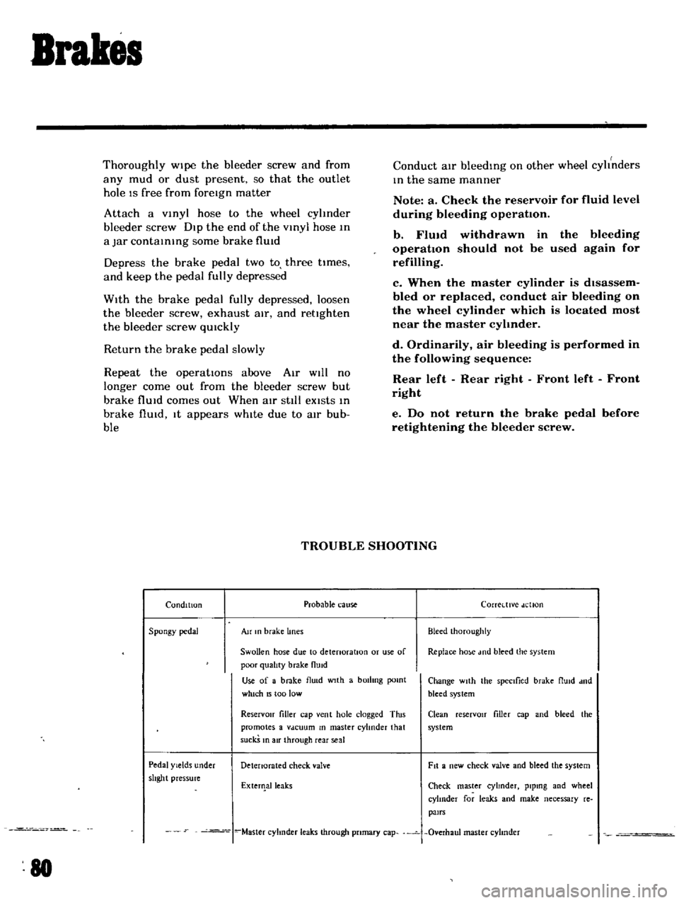
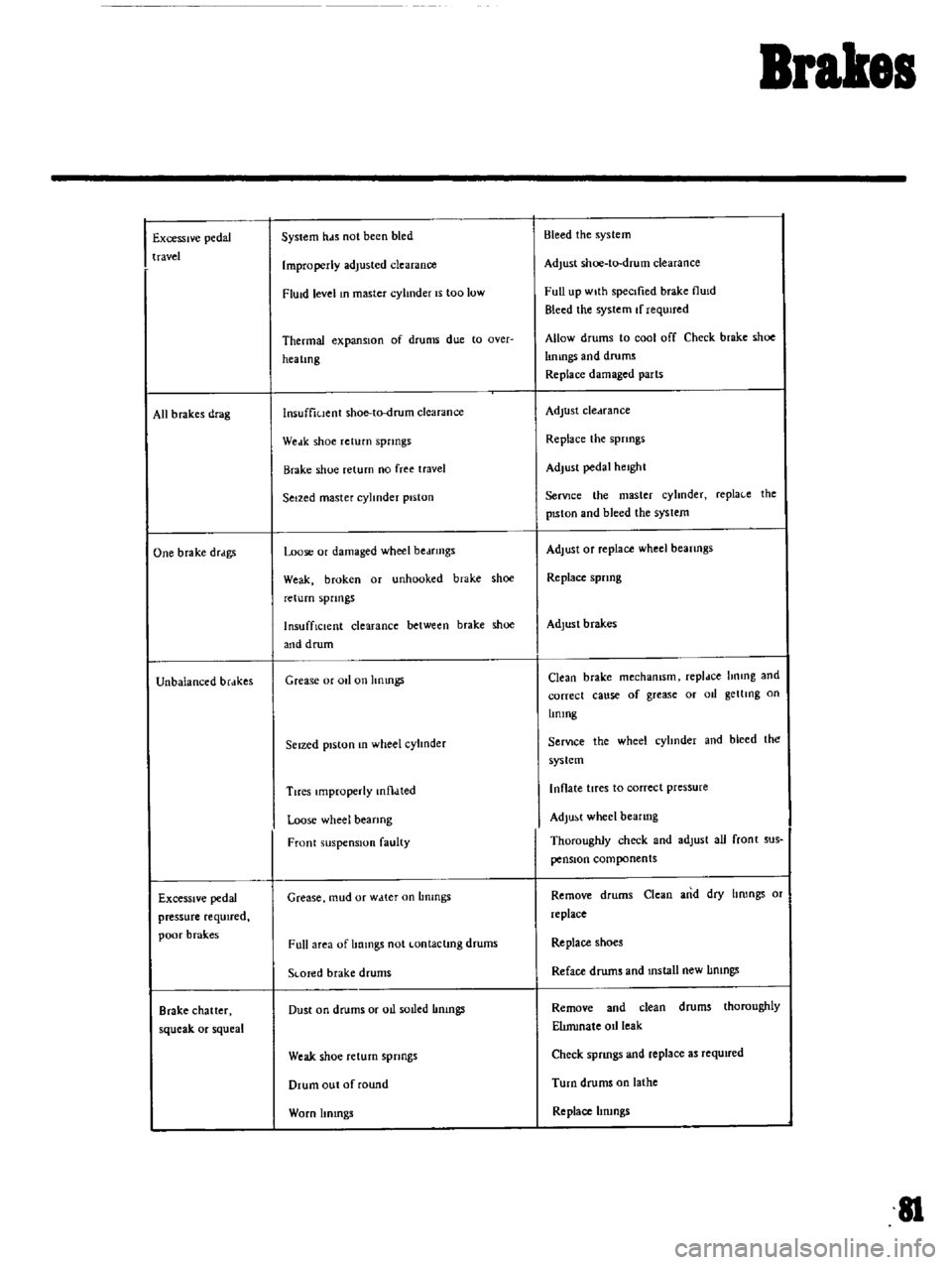
TROUBLE
SHOOTING
Condition
Probable
cause
Corretttve
dellon
Spongy
pedal
Au
In
brake
lines
Bleed
Ihoroughly
Swollen
hose
due
to
detenoratlOn
or
use
of
Replace
ho
e
md
bleed
the
system
poor
qualIty
brake
flUid
Use
of
a
brake
flu
d
wIth
a
bOilIng
pomt
Change
wIth
the
spectlied
brake
flUId
dnd
which
15
too
low
bleed
system
ReservOir
filler
cap
vent
hole
clogged
Tins
Clean
reserVOIr
filler
cap
and
bleed
the
promotes
a
Vdcuum
In
master
cylinder
that
system
suckS
In
air
through
rear
seal
Pedal
Yields
under
Detenorated
check
valve
Fit
a
new
check
valve
and
bleed
the
system
shght
pressure
ExterIlalleaks
Check
master
cyhnder
plpmg
and
wheel
cylInder
for
leaks
and
make
necessary
re
pairs
Master
cyhnder
leaks
through
pnmary
cap
Overhaul
master
cyhnder
80
Page 76 of 136
Brakes
Excessive
pedal
travel
All
b
rakes
drag
One
brake
drdgs
Unbalanced
brdkes
Excessive
pedal
pressure
required
poor
brak
es
Brake
chatter
squeak
or
squeal
System
hds
not
been
bled
Improperly
adjusted
clearance
FlUid
level
In
master
cylinder
IS
too
low
Thermal
expansIOn
of
drums
due
to
Qver
hea
lmg
lnsuffiuent
shoe
to
drum
clearance
Weak
shoe
return
springs
Brake
shoe
return
no
free
travel
Seized
master
cylinder
piston
Loose
or
damaged
wheel
bedfmgs
Weak
broken
or
unhooked
brake
shoe
return
spnngs
InsuffiCient
clearance
between
brake
shoe
and
drum
Grease
or
011
on
hnmgs
Seized
piston
In
wheel
cylInder
Tires
Improperly
mtl
lted
Loose
wheel
bearing
Front
suspension
faulty
Grease
mud
or
w
tter
on
Lmmgs
Full
area
of
Immgs
not
Lontaclmg
drums
SLOTed
brake
drums
Dust
on
drums
or
oIl
soLled
Immgs
Weak
shoe
return
springs
Drum
out
of
round
Worn
Itmngs
Bleed
the
system
Adjust
shoe
to
drum
clearance
Full
up
wIth
specIfied
brake
flUId
Bleed
the
system
If
requIred
Allow
drums
to
cool
off
Check
brake
shoe
lImngs
and
drums
Replace
damaged
parts
Adjust
cledrance
Replace
the
spnngs
Adjust
pedal
height
SerVJce
the
master
cyhnder
repla
e
the
pISton
and
bleed
the
syslem
Adjust
Of
replace
wheel
beanngs
Replace
spnng
Adjust
brakes
Clean
brake
mechamsm
repldce
hnmg
and
correct
cause
of
grease
or
011
getllng
on
Lmmg
SerVIce
the
wheel
cyhnder
and
bleed
the
system
Inflate
tires
to
correct
pressure
Adjust
wheel
bearing
Thoroughly
check
and
adlust
all
front
sus
pensIOn
components
Remove
drums
Clean
and
dry
hrongs
or
replace
Replace
shoes
Reface
drums
and
mstall
new
IImngs
Remove
and
clean
drums
thoroughly
ElImmale
oIl
leak
Check
spnngs
and
replace
as
required
Turn
drums
on
lathe
Replace
hrungs
II
Page 93 of 136
Clutch
Pedal
lever
bush
Fulcrum
pedal
pIn
etc
Remstallation
Reinstall
the
clutch
pedal
In
reverse
sequence
of
removal
Adjustment
Adjust
pedal
pad
heIght
to
565
In
Without
stopper
The
adjustment
IS
made
by
selectmg
and
applYIng
shlm
s
haVing
adequate
thIckness
Be
Ule
to
use
shIms
haVIng
same
thIckness
for
both
upper
and
lower
Next
adjust
the
pedal
stopper
properly
so
that
the
pedal
pad
height
IS
557
In
and
secure
the
pOSitIOn
WIth
lock
nut
Note
Make
sure
that
chaSSIS
grease
has
been
applied
to
the
CG
marked
portions
two
places
Grease
if
reqUired
CLUTCH
MASTER
CYLINDER
Removal
DIsconnect
the
push
rod
from
the
cleVIS
DIsconnect
the
clutch
lIne
from
the
master
cylinder
and
draIn
flUid
Remove
the
ecunng
bolts
and
remove
the
master
cyhnder
assembly
from
the
vehIcle
DIsassembly
Remove
the
filler
cap
and
draIn
flUId
Pull
back
the
dust
cover
and
remove
the
snap
rIng
The
stopper
push
rod
pIston
assembly
pnmary
cup
and
return
sptlng
assembly
can
be
removed
Inspection
Thoroughly
clean
all
parts
With
brake
flUId
before
InspectIOn
Check
the
cyhnder
and
piston
for
uneven
wear
or
damage
Replace
If
required
When
clearance
between
the
cylinder
and
pIston
IS
more
than
O
0059
In
replace
the
cyhnder
102
Replace
the
pIston
cup
pnmanly
whenever
the
master
cyhnder
IS
dIsassembled
It
must
also
be
replaced
when
wear
or
deformatIOn
due
to
fatIgue
or
damage
IS
found
Check
the
dust
cover
OIl
reservOIr
filler
cap
and
clutch
lIne
for
damage
or
deformatIOn
If
abnormal
condItIOn
IS
found
replace
With
new
one
Reassembly
Reassemble
the
master
cylInder
assembly
In
reverse
sequence
of
dIsassembly
notIng
the
follOWIng
matters
The
pIston
cup
should
be
soaked
In
brake
flUId
before
reassembly
Install
the
pIston
cup
carefully
so
that
It
IS
correctly
faced
Apply
brake
flUId
suffiCIently
to
the
cyhnder
and
pIston
and
assemble
them
Reinstallation
ReInstall
the
master
cyhnder
assembly
In
reverse
sequence
of
removal
and
adjust
as
follows
Adjust
the
pedal
heIght
by
changmg
the
push
rod
length
Bleed
air
out
of
the
hydrauhc
system
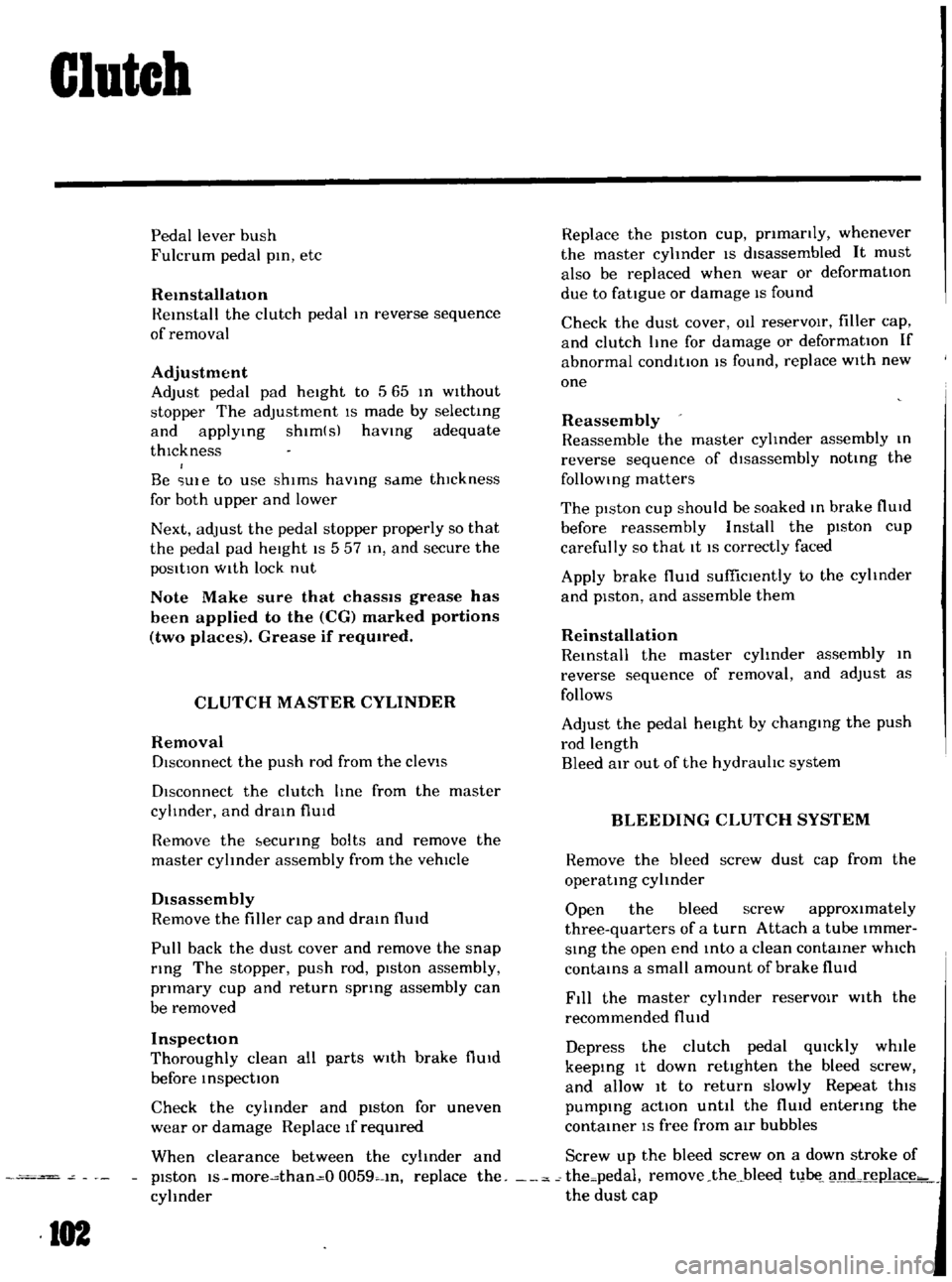
BLEEDING
CLUTCH
SYSTEM
Remove
the
bleed
screw
dust
cap
from
the
operatIng
cyhnder
Open
the
bleed
screw
approximately
three
quarters
of
a
turn
Attach
a
tube
Immer
SIng
the
open
end
mto
a
clean
contaIner
which
contaInS
a
small
amount
of
brake
flUId
Fill
the
master
cyhnder
reservOIr
With
the
recommended
flUId
Depress
the
clutch
pedal
qUIckly
while
keepIng
It
down
retighten
the
bleed
screw
and
allow
It
to
return
slowly
Repeat
thiS
pumpIng
actIOn
unttl
the
flUId
entenng
the
contaIner
IS
free
from
air
bubbles
Screw
up
the
bleed
screw
on
a
down
stroke
of
the
pedal
remove
the
bleec
t1
1
nd
rel1lace
the
dust
cap
Page 99 of 136
Transmission
AUTOMATIC
TRANSMISSION
The
model
3N71B
automatic
transmiSSIOn
IS
a
fully
automatic
Unit
consisting
pnmanly
of
3
element
hydrauhc
torque
converter
and
two
planetary
gear
sets
Two
multiple
disc
clut
ches
a
multiple
disc
brake
a
band
brake
and
a
one
way
sprag
clutch
provide
the
fnctlon
elements
reqUired
to
obtain
the
deSired
fun
tlon
of
the
two
planetary
gear
sets
The
two
planetary
gear
sets
give
three
for
ward
ratIOs
and
one
reverse
Changing
of
the
gear
ratIOs
IS
fully
automatic
In
relation
to
vehicle
speed
and
engine
torque
Input
Vehicle
speed
and
engine
mamfold
vacuum
Signals
are
constantly
fed
to
the
transmiSSIOn
to
prOVide
the
proper
gear
ratIO
for
maximum
effiCiency
and
performance
at
all
throttle
openmgs
The
Model
3N71B
has
SIX
selector
poSitIOns
P
R
N
D
2
1
p
Park
pOSitIOn
posItively
locks
the
out
put
shaft
to
the
transmiSSIOn
case
by
means
of
a
lockmg
pawl
to
prevent
the
vehicle
from
rollmg
either
directIOn
ThiS
pOSitIOn
should
be
selected
whenever
the
dnver
leaves
the
vehicle
The
engme
may
be
started
m
Park
pOSition
R
Reverse
range
enables
the
vehicle
to
be
operated
m
a
reverse
direction
N
Neutral
pOSitIOn
enables
the
engine
to
be
started
and
run
Without
dnvIngthe
vehicle
0
Drive
range
IS
used
for
all
normal
driVing
conditions
Dnve
range
has
three
gear
ratios
from
the
startmg
ratIO
to
direct
dnve
2
2
range
prOVides
performance
for
dnvIng
onshppery
surfaces
2
range
can
also
be
used
for
engine
brakmg
2
range
can
be
selected
at
any
vehicle
speed
and
prevents
the
transmlsslOn
from
shifting
out
of
second
gear
108
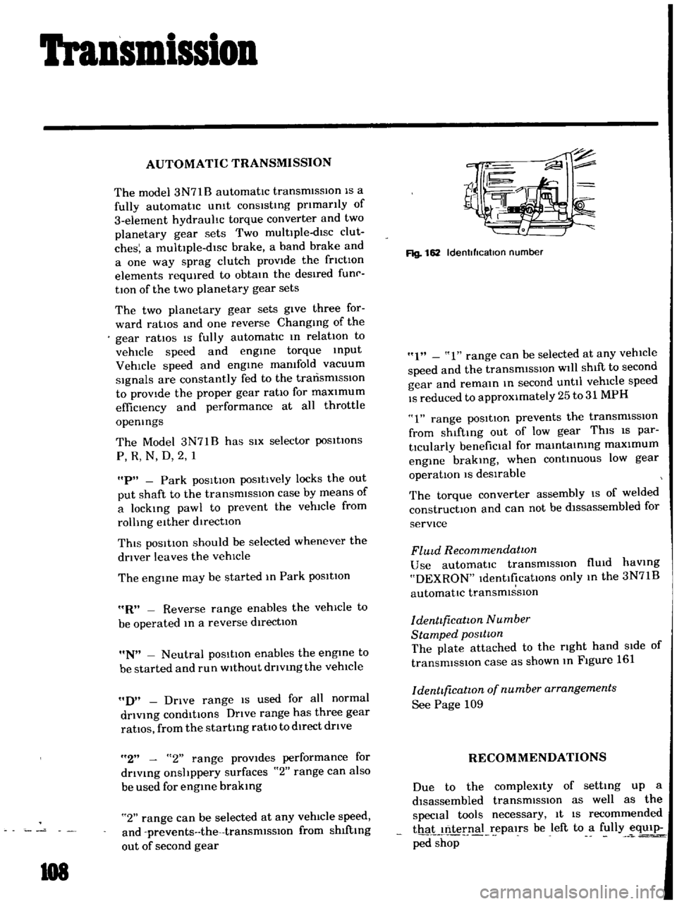
Rg
162
Idenllflcatlon
number
I
1
range
can
be
selected
at
any
vehicle
speed
and
the
transmiSSIOn
will
shift
to
second
gear
and
remain
m
second
until
vehicle
speed
IS
reduced
to
approximately
25
to
31
MPH
1
range
posItion
prevents
the
transmiSSIOn
from
shlftmg
out
of
low
gear
ThiS
IS
par
tlcularly
benefiCial
for
mamtamIng
maximum
engine
brakmg
when
continUOUS
low
gear
operation
IS
deSirable
The
torque
converter
assembly
IS
of
welded
constructIOn
and
can
not
be
dlssassembled
for
service
FlUld
Recommendatwn
Use
automatic
transmiSSIOn
flUid
haVing
DEXRON
IdentificatIOns
only
m
the
3N71B
automatic
transmiSSIOn
denttficatwn
Number
Stamped
posttwn
The
plate
attached
to
the
rIght
hand
Side
of
transmission
case
as
shown
m
Figure
161
denttficatwn
of
number
arrangements
See
Page
109
RECOMMENDATIONS
Due
to
the
compleXity
of
setting
up
a
disassembled
transmissIOn
as
well
as
the
special
tools
necessary
It
IS
recommended
thaL
nternal
epalrs
be
left
to
a
fully
eqUip
ped
shop
Page 119 of 136
Specifications
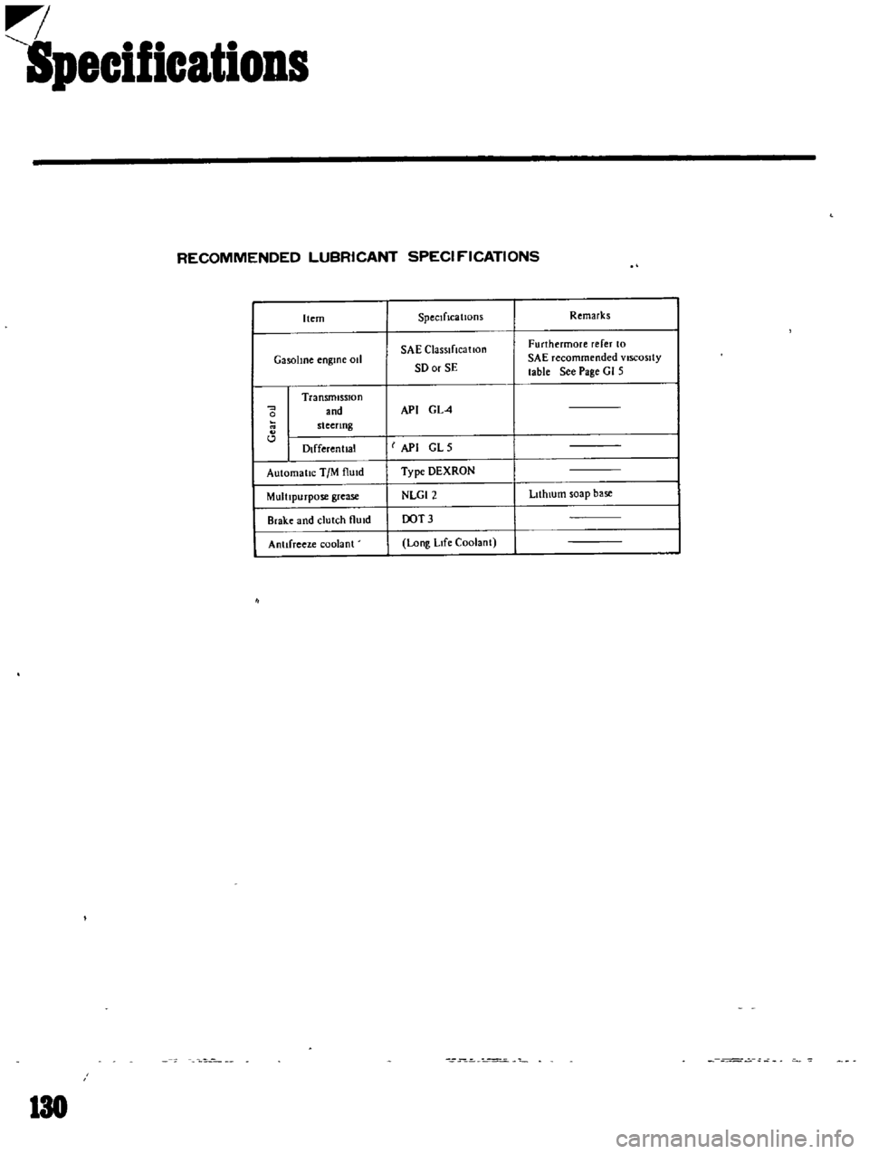
RECOMMENDED
LUBRICANT
SPECI
f
ICATIONS
Item
SpeCificatiOnS
Remarks
SAE
ClaSSIfIcatIon
Furthermore
refer
to
GasolIne
engme
011
SD
or
SE
SAE
recommended
VISCOSity
table
See
Page
GI
5
Transmission
and
API
GL4
0
steenng
l
Dlfferenllal
I
API
GLS
Automallc
TIM
flUId
Type
DEXRON
MultIpurpose
grease
NLGI2
LIthIUm
soap
base
Brake
and
clutch
flUId
OOT3
Antifreeze
coolant
Long
LIfe
Coolant
130