1969 DATSUN B110 boot
[x] Cancel search: bootPage 15 of 136
Bngine
WIres
for
accelerator
and
choke
The
operatIOn
Will
be
carned
out
more
easily
by
removing
the
a1r
cleaner
Lift
up
the
engine
toward
the
front
INST
ALLA
TION
Install
the
engine
In
reverse
sequence
of
removal
Disconnecting
clutch
wire
on
nght
hand
dnve
model
On
left
hand
dnve
model
disconnect
hydraulIc
line
from
the
clutch
slave
cylInder
DIsconnect
the
clutch
WIre
at
the
JXlrtlOn
of
the
wIthdrawal
lever
Remove
the
exhaust
front
tube
Disconnect
the
the
cable
to
the
back
up
lamp
SWItch
D1sconnect
the
speedometer
cable
Remove
the
propeller
shaft
Remove
four
bolts
used
In
the
differential
carner
SIde
and
Withdraw
the
propeller
shaft
Remove
the
shift
lever
Model
With
remote
control
shIft
lever
Disconnect
the
remote
control
rod
at
the
JXlr
tlOn
of
transmiSSIOn
outer
lever
and
remove
the
remote
control
rod
Model
With
floor
Sh1ft
lever
Remove
the
boot
WIthdraw
the
lock
pin
and
remove
the
lever
The
operatIOn
IS
carned
out
In
the
passenger
compartment
Model
With
automatic
transmiSSIOn
Remove
pinS
from
both
ends
of
the
cross
shaft
and
remove
the
shIft
rod
Suspend
the
engine
With
wire
Remove
the
front
engine
mounting
installation
nuts
Remove
the
rear
engine
mounting
installation
nuts
When
removing
the
engine
mounting
in
stallation
nuts
be
sure
to
apply
a
Jack
beneath
the
transmiSSIOn
CLEANING
AND
INSPECTION
Clean
the
engine
thoroughly
before
disassem
bly
Before
cleaning
the
engine
remove
the
l
electncal
parts
and
plug
up
the
carburetor
air
horn
to
aVOid
intrusIOn
of
foreign
matter
The
engine
extenor
Check
the
covers
and
bolts
for
breakage
rust
damage
and
loss
CylInder
block
Check
thoroughly
the
water
Jacket
for
cracks
and
breakage
Clutch
hOUSing
Check
for
cracks
011
pan
Check
for
excessive
rust
DISASSEMBLY
Mount
engine
assembly
on
engine
stand
Remove
the
engine
mounting
bracket
R
H
Side
Install
the
engine
attachment
Mount
the
engine
on
the
stand
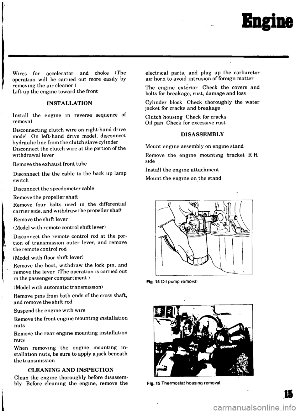
Fig
14011
pump
removal
Fig
15
Thermostat
hOUSing
removal
II
Page 44 of 136
Ignition
Sptem
The
standard
breaker
pOint
spring
tensIOn
IS
1
1
to
1
4
lb
Replace
If
devIated
Performance
of
condenser
IS
affected
by
Im
proper
setting
contaminatIOn
and
reductIOn
of
In
ulatlOn
resIstance
Thus
pellOdlcal
checking
I
I
eqlJ
lred
to
maintain
the
outlet
of
lead
wire
clean
and
to
prevent
et
screw
from
loosening
Checking
the
condenser
capacIty
IS
checked
USing
a
capacity
meter
It
may
be
also
checked
condenser
Isolate
resl
tance
USing
a
tester
by
adjusting
ItS
I
ange
to
measure
large
I
eSlstance
value
When
the
condenser
IS
normal
the
tester
pOinter
SWings
1m
gely
and
rapIdly
and
moves
gradually
back
to
the
Infimte
SIde
When
the
pOinter
does
not
stay
stili
or
It
points
Zero
In
reSIstance
replacement
IS
necessary
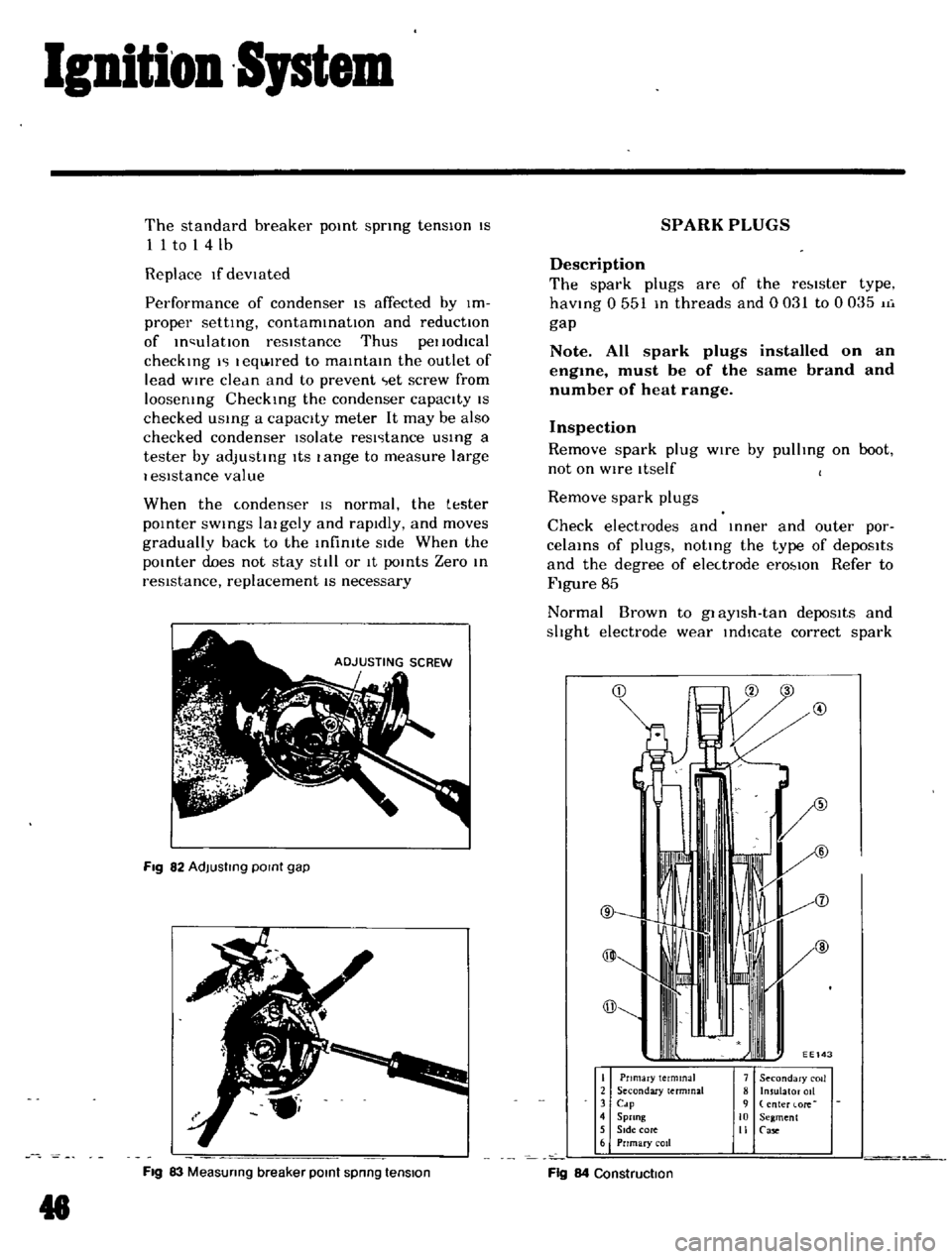
Fig
82
AdJusllng
POint
gap
Fig
83
Measunng
breaker
POint
spnng
tension
g
SPARK
PLUGS
Description
The
spark
plugs
are
of
the
re
lster
type
haVing
0
551
In
threads
and
0031
to
0035
11i
gap
Note
All
spark
plugs
installed
on
an
engme
must
be
of
the
same
brand
and
number
of
heat
range
Inspection
Remove
spark
plug
wIre
by
pulhng
on
boot
not
on
WIre
Itself
Remove
spark
plugs
Check
electrodes
and
Inner
and
outer
por
celams
of
plugs
noting
the
type
of
depOSits
and
the
degree
of
electrode
erO
lOn
Refer
to
Figure
85
Normal
Brown
to
gl
aYlsh
tan
depoSits
and
shght
electrode
wear
indIcate
correct
spark
@
I
Pnmary
terminal
2
Secondary
terminal
3
Cdp
4
Sprang
5
SIde
core
6
Prrmary
coil
7
Secondary
COIl
8
Insulator
011
9
enter
lore
10
Segment
II
Case
Fig
84
Construction
Page 66 of 136
Brakes
DIsassembly
Remove
mud
and
other
contamInations
from
the
caLiper
as
embly
before
dlsa
sembly
DraIn
bl
ake
fluId
flOm
the
wheel
cylinder
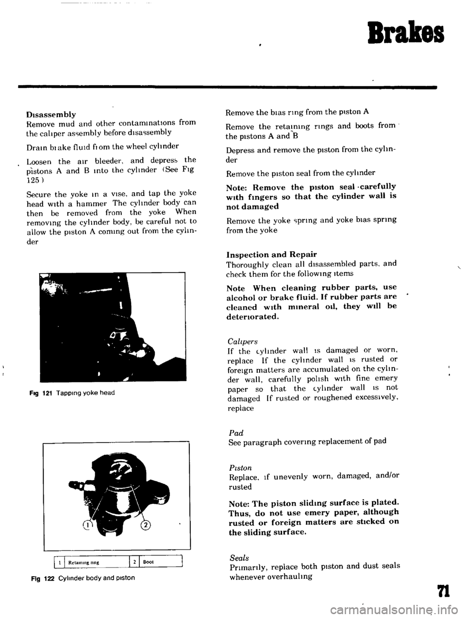
Loosen
the
aIr
bleeder
and
depres
the
pistons
A
and
B
Into
the
cylInder
See
FIg
125
Secure
the
yoke
In
a
vIse
and
tap
the
yoke
head
with
a
hammer
The
cylinder
body
can
then
be
removed
from
the
yoke
When
remOVIng
the
cylinder
body
be
careful
not
to
allow
the
piston
A
comIng
out
from
the
cylIn
der
FIg
121
TapPing
yoke
head
5
I
B
Q
Retamlng
nng
J
Boot
Fig
122
Cylinder
body
and
piston
Remove
the
bIas
nng
from
the
piston
A
Remove
the
retaInIng
nngs
and
boots
from
the
pistons
A
and
B
Depress
and
remove
the
piston
from
the
cylin
der
Remove
the
piston
seal
from
the
cylinder
Note
Remove
the
p1ston
seal
carefully
w1th
fmgers
so
that
the
cylinder
wall
is
not
damaged
Remove
the
yoke
prIng
and
yoke
bias
sprIng
from
the
yoke
Inspection
and
Repair
Thoroughly
clean
all
dIsassembled
parts
and
check
them
for
the
follOWIng
Items
Note
When
cleaning
rubber
parts
use
alcohol
or
brake
fluid
If
rubber
parts
are
cleaned
wIth
mmeral
Oil
they
will
be
detenorated
Calzpers
If
the
cylInder
wall
IS
damaged
or
worn
replace
If
the
cylinder
wall
IS
rusted
or
foreIgn
matters
are
accumulated
on
the
cylIn
der
wall
carefully
polIsh
wIth
fine
emery
paper
so
that
the
cylInder
wall
IS
not
damaged
If
rusted
or
roughened
excessively
replace
Pad
See
paragraph
covenng
replacement
of
pad
PIston
Replace
If
unevenly
worn
damaged
and
or
rusted
Note
The
piston
slidmg
surface
is
plated
Thus
do
not
use
emery
paper
although
rusted
or
foreign
matters
are
sttcked
on
the
sliding
surface
Seals
Prlmanly
replace
both
pIston
and
dust
seals
whenever
overhauling
n
Page 67 of 136
Brakes
Note
The
piston
seal
affects
not
only
Ieakmg
but
also
piston
return
For
this
reason
replace
the
piston
seal
even
If
the
damage
IS
minor
Rotor
Check
the
rotor
and
If
It
shows
cOl
e
ex
cesslvely
out
of
round
and
so
forth
recon
ditIOnIng
by
machInIng
l
l
requIred
If
any
ab
normal
condItIOns
such
as
crack
dl
ltortlOn
and
excessIve
deflectIOn
replace
the
rotor
Standard
rotor
thlckne
ls
03740
In
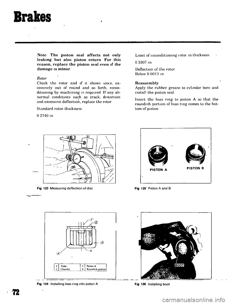
Fig
123
MeaSUring
deflectoon
of
diSC
Fig
124
Installing
bias
ring
mto
piston
A
72
LImIt
of
I
econdltlOntng
lotOl
In
thlcknes
l
o
3307
In
DeflectIOn
of
the
rotor
Below
0
0012
In
Reassembly
Apply
the
rubber
grea
le
to
cylinder
bore
and
Install
the
pIston
seal
Insert
the
bIas
rIng
to
pIston
A
so
that
the
roundl
lh
portIon
of
bIas
ring
comes
to
the
bot
tom
of
pIston
A
PISTON
B
PISTON
A
Fig
125
Piston
A
and
B
Fig
126
Installing
boot
Page 68 of 136
Brakes
Note
Be
careful
not
to
confuse
the
piston
A
with
B
Apply
rubber
grease
hghtly
to
the
shdlng
par
tlon
of
p1ston
and
Insert
the
piston
Into
the
cyhnder
Note
When
insertmg
the
piston
be
careful
not
to
insert
too
far
Install
the
boot
and
retaining
nng
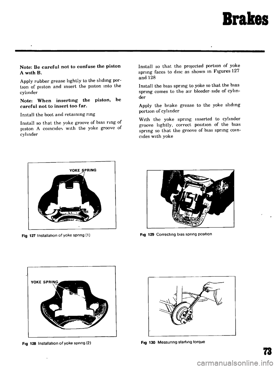
Install
so
that
the
yoke
groove
of
bIas
nng
of
piston
A
COinCide
wIth
the
yoke
groove
of
cyhnder
YOKE
SPRING
Fig
127
Installation
of
yoke
spnng
1
Fig
128
InstallatIOn
of
yoke
spnng
2
Install
so
that
the
projected
portIOn
of
yoke
spnng
faces
to
diSC
as
shown
In
Figures
127
and
128
Install
the
bias
spring
to
yoke
so
that
the
bias
spring
comes
to
the
aIr
bleeder
Side
of
cyhn
der
Apply
the
brake
grease
to
the
yoke
shdlng
portIOn
of
cylinder
With
the
yoke
spring
Inserted
to
cylinder
groove
hghtly
correct
poSitIOn
of
the
bias
spnng
so
that
the
groove
of
biaS
spring
COin
Cides
With
yoke
Fig
129
Correctmg
bias
spnng
POSItion
Fig
130
Measunng
startmg
torque
73