1969 DATSUN B110 fuel pump
[x] Cancel search: fuel pumpPage 4 of 136

able
of
Contents
MAINTENANCE
TUNE
UP
DIsassembly
32
InspectIOn
RepaIr
33
VALVE
CLEARANCES
6
AdJustmg
Regulator
33
ENGINE
OIL
6
Assembly
33
OIL
FILTER
7
COOLANT
7
COMPRESSION
7
ELECTRICAL
SYSTEM
BATTERY
8
IGNITION
TIMING
8
STARTER
36
DIstributor
Breaker
Pomt
9
Removal
37
Condenser
9
InstallatIOn
37
Spark
Plugs
9
Trouble
Shootmg
37
Carburetor
9
ALTERNATOR
36
Idle
LImIter
Cap
10
Removal
37
Dash
Pot
automatic
transmISSIOn
11
InstallatIOn
37
model
only
11
REGULATOR
39
Carburetor
Return
Sprmg
11
DeSCriptIOn
39
Fuel
Filter
11
Trouble
Shootmg
40
ENGINE
IGNITION
SYSTEM
DESCRIPTION
14
DISTRIBUTOR
44
REMOVAL
14
ConstructIOn
44
INSTALLATION
14
Checkmg
and
Adjustment
44
CLEANING
INSPECTION
14
SP
ARK
PLUGS
46
DISASSEMBL
Y
14
DeSCriptIOn
46
INSPECTION
REPAIR
18
InspectIOn
46
PreparatIOn
18
Cleamng
Regap
47
Cyltnder
Head
18
Valve
Assembly
18
Valve
Spnng
19
Valve
Rocker
Shaft
Rocker
Arm
19
FUEL
SYSTEM
Valve
LIfter
Push
Rod
20
Camshaft
Camshaft
Bearmg
20
FUEL
FILTER
50
Valve
Tlmmg
20
DESCRIPTION
50
Cyltnder
Block
21
REMOVAL
50
PIston
Piston
Pm
Plsto
LRmg
21
INSTALLATION
50
Connectmg
Rod
23
FUEL
PUMP
50
Crankshaft
24
DeSCriptIOn
50
Bushmg
Bearing
24
Testmg
51
Crankshaft
Sprocket
Removal
DIsassembly
52
Camshaft
Sprocket
25
InspectIOn
52
Flywheel
25
Assembly
52
ASSEMBL
Y
25
CARBURETOR
52
PrecautIOn
25
DeSCription
52
Cyltnder
Head
25
Adjustment
53
PIston
ConnectIng
Rod
26
Removal
58
Engme
26
DIsassembly
58
OIL
PUMP
32
Cleanmg
InspectIOn
59
Removal
Engme
m
vehicle
32
Assembly
InstallatIOn
60
I
Page 16 of 136
Bngine
Remove
the
altel
nator
and
engine
mounting
bracket
L
H
slde
Remove
the
crankshaft
pulley
Remove
the
011
pump
together
With
the
011
filtel
Remove
the
high
tensIOn
cable
wIth
the
dlstnbutor
cap
on
Remove
the
spark
plugs
Remove
the
dlstllbutor
assembly
Remove
the
carburetor
Remove
the
rocker
cover
Remove
the
thermo
itat
houslllg
Remove
the
manifolds
Remove
the
water
pump
Remove
the
fuel
pump
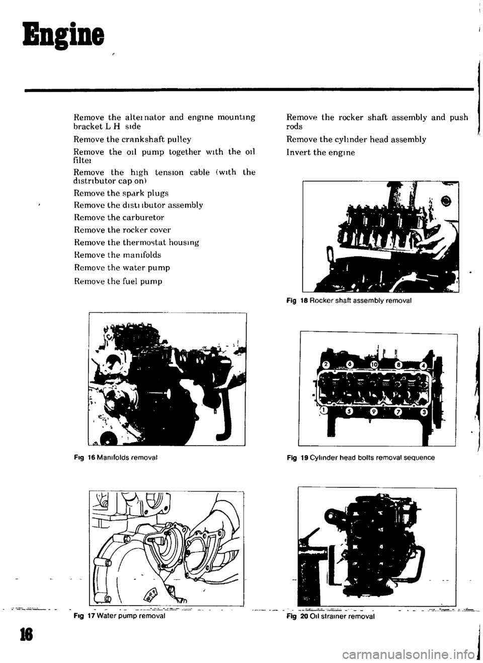
Fig
16
Manifolds
removal
Fig
17
Water
pump
removal
18
Remove
the
rocker
shaft
assembly
and
push
rods
Remove
the
cylInder
head
assembly
Invert
the
engine
Fig
18
Rocker
shaft
assembly
removal
7
1
l
I
h
Y
r
I
w
L
1
Fig
19
Cylinder
head
bolts
removal
sequence
o
Fig
20
011
strainer
removal
j
Page 31 of 136
BDgiDe
TIghtening
torque
40
to
43
ft
Ib
Install
the
push
rod
Install
the
rocker
haft
assembly
and
tighten
the
I
ocker
haft
bracket
bolts
to
the
specIfied
torque
Tightening
torque
15
to
18
ft
lb
Note
TIghtening
operation
should
be
made
gradually
10
separating
two
or
three
stages
and
outwardly
from
the
center
bracket
In
tall
the
Intake
and
exhaust
mamfolds
TIghtening
torque
65
to
10
ft
lb
AdJu
t
valve
clemance
wIth
the
specIfied
dlmenblOn
Install
the
rocker
cover
and
carburetor
assem
bly
I
n
tdll
the
watel
pump
and
thermostat
Tlghtemng
tOl
que
65
to
10
ft
lb
I
nstall
the
crankshaft
pulley
Tighten
the
crank
pulley
bolt
to
the
specIfied
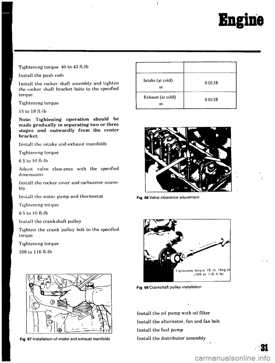
torque
TIghtenIng
torque
109
to
116
ft
lb
Fig
67
Installation
of
Intake
and
exhaust
manifolds
Intake
at
cold
00138
In
Exhaust
at
cold
00138
In
Fig
68
Valve
clearance
adjustment
TlqhtCnlnq
torque
15
to
16kg
m
109
to
116ltlb
Fig
69
Crankshaft
pulley
installation
Install
the
at
pump
with
011
filter
Install
the
alternator
fan
and
fan
belt
Install
the
fuel
pump
Install
the
dlstnbutor
assembly
31
Page 32 of 136
BBgiBe
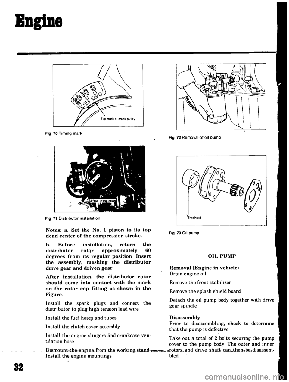
Fig
70
Tlmmg
mark
Fig
71
Dlstnbutor
mstallatlon
Notes
a
Set
the
No
1
piston
to
its
top
dead
center
of
the
compression
stroke
b
Before
installation
return
the
distributor
rotqr
approximately
60
degrees
from
Its
regular
position
Insert
the
assembly
meshing
the
distributor
drive
gear
and
driven
gear
After
installation
the
distributor
rotor
should
come
into
contact
wIth
the
mark
on
the
rotor
cap
fittmg
as
shown
in
the
Figure
Install
the
spark
plugs
and
connect
the
distrIbutor
to
plug
high
tensIOn
lead
wire
Install
the
fuel
hoses
and
tubes
Install
the
clutch
cover
assembly
Install
the
engme
shngers
and
crankcase
ven
tilatIOn
hose
Fig
72
Removal
of
011
pump
TrochoId
Fig
73011
pump
OIL
PUMP
Removal
Engine
in
vehlCIe
Dram
engme
OIl
Remove
the
front
stabilIzer
Remove
the
splash
shield
board
Detach
the
011
pump
body
together
with
drIve
gear
spmdle
Disassembly
PrIor
to
dlsassembhng
check
to
determme
that
the
pump
IS
defective
Take
out
a
total
of
2
bolts
securmg
the
pump
cover
to
the
pump
body
The
outer
and
mner
Dlsmount
the
engme
from
the
workmg
stand
rotors
and
drive
shaft
can
then
be
dlsassem
Install
the
engme
mountmgs
bled
32
Page 45 of 136
Icnition
Sptem
Ovcrhc
Jtmg
Norm
Jl
i
r
rJ
I
ttr
I
i
V
Carbon
fould
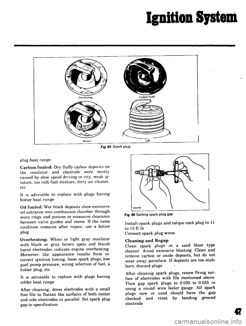
Fig
85
Spark
plug
Life
plug
heat
range
Carbon
fouled
Dry
fluffy
carbon
depo
lts
on
the
Insulator
and
electrode
were
mostly
caused
by
slow
speed
dnvlng
In
cIty
weak
Ig
nltlOn
too
nch
fuel
mixture
dirty
aIr
cleaner
etc
It
IS
advIsable
to
replace
WIth
plugs
havmg
hotter
heat
range
011
fouled
Wet
black
depoSits
show
excesSive
oIl
entrance
Into
combusllon
chamber
through
worn
rmgs
and
pIstons
or
excessIve
clearance
between
valve
gUIdes
and
stems
If
the
same
condition
remams
after
repair
use
a
hotter
plug
Overheatmg
WhIte
or
hght
gray
msulator
WIth
black
or
gray
brown
spots
and
blUIsh
burnt
electrodes
indIcate
engme
overheatIng
Moreover
th
e
appearance
results
from
in
correct
IgnitIon
tIming
loose
spark
plugs
low
guel
pump
pressure
wrong
selectIOn
of
fuel
a
hotter
plug
etc
It
IS
adVisable
to
replace
WIth
plugs
havmg
colder
heat
range
After
cleaning
dress
electrodes
With
a
small
fine
file
to
flatten
the
surfaces
of
both
center
and
Side
electrodes
In
parallel
Set
spark
plug
gap
to
specification
FIg
86
Settmg
spark
plug
gap
Install
spark
plugs
and
torque
each
plug
to
11
to
15
ft
Ib
Connect
spark
plug
wires
Cleaning
and
Regap
Clean
spark
plugs
In
a
sand
blast
type
cleaner
A
VOId
excessIve
blasting
Clean
and
remove
carbon
or
OXide
depoSits
but
do
not
wear
away
porcelain
If
depos1ts
are
too
stub
born
discard
plugs
After
cleaning
spark
plugs
renew
firing
sur
face
of
electrodes
With
file
mentioned
above
Then
gap
spark
plugs
to
0
030
to
0
035
In
uSing
a
round
wire
feeler
gauge
All
spark
plugs
new
or
used
should
have
the
gap
checked
and
reset
by
bending
ground
electrode
II
Page 47 of 136
ruel
Sptem
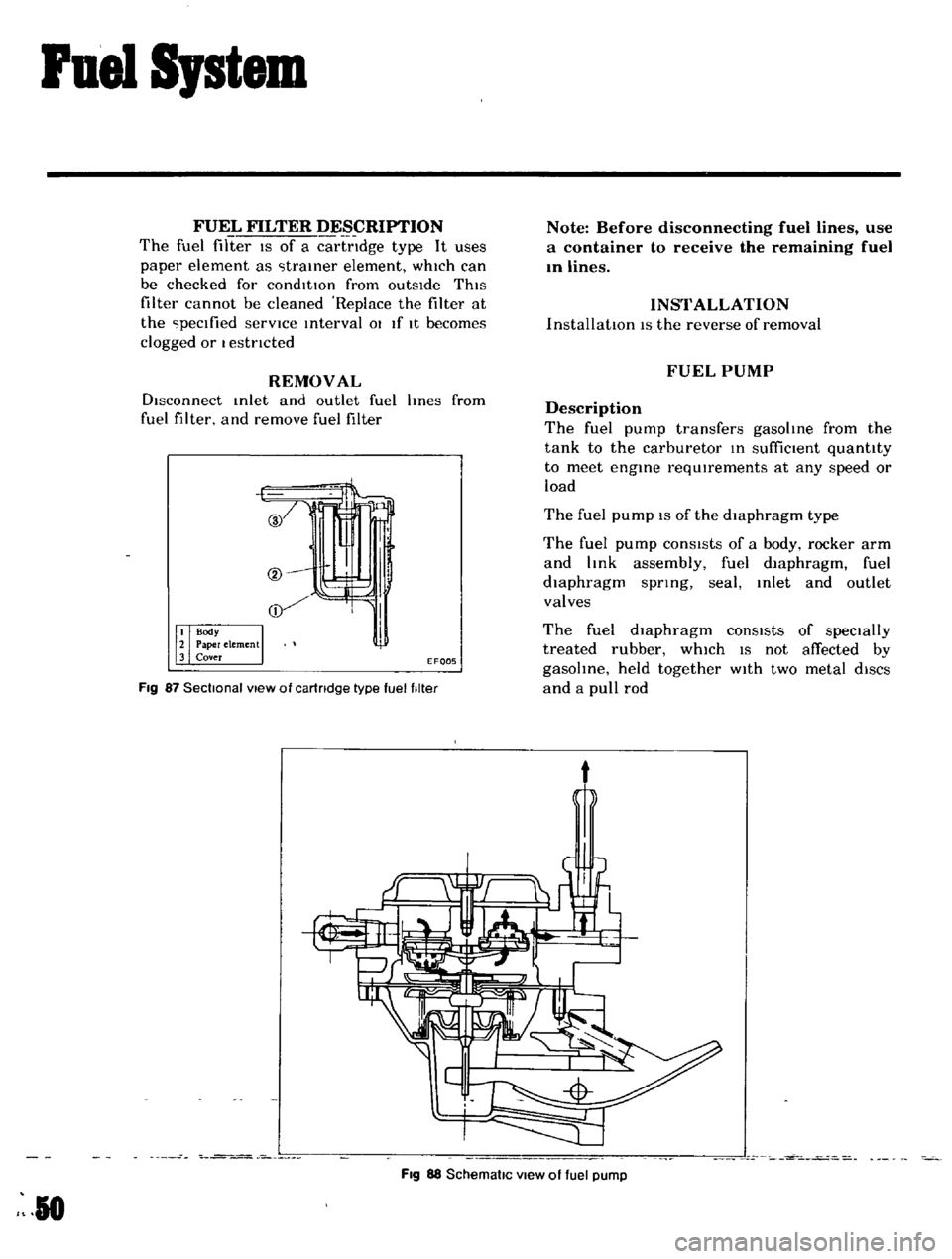
FUEL
FILTER
DESCRIPTION
The
fuel
filter
IS
of
a
cartndge
type
It
uses
paper
element
as
traIner
element
which
can
be
checked
for
condItIOn
from
outsIde
ThIS
filter
cannot
be
cleaned
Replace
the
filter
at
the
peclfied
servICe
Interval
01
If
It
becomes
clogged
or
I
estncted
REMOVAL
DIsconnect
Inlet
and
outlet
fuel
hnes
from
fuel
filter
and
remove
fuel
filter
if
EF005
Fig
87
Sectional
view
of
cartridge
type
fuel
filter
Note
Before
disconnecting
fuel
lines
use
a
container
to
receive
the
remaining
fuel
In
lines
INSTALLATION
InstallatIOn
IS
the
reverse
of
removal
FUEL
PUMP
Description
The
fuel
pump
transfers
gasoline
from
the
tank
to
the
carburetor
In
suffiCient
quantity
to
meet
engine
requIrements
at
any
speed
or
load
The
fuel
pump
IS
of
the
diaphragm
type
The
fuel
pump
conSIsts
of
a
body
rocker
arm
and
link
assembly
fuel
diaphragm
fuel
diaphragm
spnng
seal
Inlet
and
outlet
valves
The
fuel
diaphragm
consists
of
specially
treated
rubber
whIch
IS
not
affected
by
gasohne
held
together
WIth
two
metal
diSCS
and
a
pull
rod
t
Fig
88
SchematiC
view
of
fuel
pump
R
0
Page 48 of 136
Fuel
Sptem
Testing
A
fuel
pump
IS
operatIng
properly
when
1tS
pressure
IS
Within
specifications
and
ItS
capacIty
IS
equal
to
the
engine
s
reqUIrements
at
all
speeds
Pressure
and
capacity
must
be
determined
by
two
tests
With
the
pump
mounted
on
the
engIne
Be
sure
that
there
IS
gasohne
m
the
tank
when
conductIng
these
tests
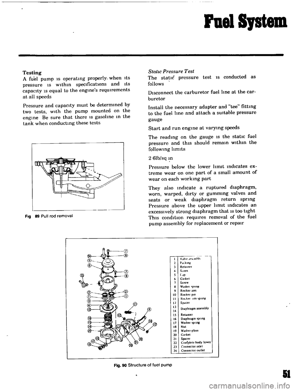
Fig
89
Pull
rod
removal
StatIc
Pressure
Test
The
static
pressure
test
IS
conducted
as
follows
Disconnect
the
carburetor
fuel
line
at
the
car
buretor
Install
the
necessary
adapter
and
tee
fitting
to
the
fuel
Ime
and
attach
a
SUitable
pressure
gauge
Start
and
run
engme
at
varymg
speeds
The
readIng
on
the
gauge
IS
the
static
fuel
pressure
and
thIS
should
remam
wlthm
the
follOWing
Itmlts
2
61b
sq
m
Pressure
below
the
lower
hmlt
IndlCates
ex
treme
wear
on
one
part
of
a
small
amount
of
wear
on
each
working
part
They
also
md1cate
a
ruptured
dIaphragm
worn
warped
dirty
or
gummmg
valves
and
seats
or
weak
dIaphragm
return
spring
Pressure
above
the
upper
hmlt
Indicates
an
excessIVely
strong
dIaphragm
that
IS
too
tight
ThIS
condItIOn
reqUIres
removal
of
the
fuel
pump
assembly
for
replacement
or
repair
I
V
lvc
llllh
2
PdlklOg
3
Retamer
4
Stre
5
p
6
Ga
ket
7
Screw
8
Washer
prln
9
Rocker
Jrm
10
Rocker
pm
II
Ro
ker
fm
pTln
12
Spdcer
13
Diaphragm
assembly
14
15
Retiuner
16
Diaphragm
sprtng
17
Washer
5PIlllg
18
Nul
19
Washer
plalO
20
Ga
ket
21
Spacer
22
Complete
body
lower
23
Connector
anlet
24
Connector
outlet
Fig
90
Structure
of
fuel
pump
51
Page 49 of 136
Fuel
Sptem
Capacity
Test
The
capaclty
test
IS
used
only
when
the
statIc
plessure
IS
wlthm
specIficatIOns
The
capacity
test
IS
conducted
as
follows
Disconnect
the
fuel
p1pe
at
the
carburetor
Place
a
bUltable
contamer
at
the
end
of
the
pIpe
Start
the
engme
and
run
at
1
000
rpm
The
pump
should
delIver
1
US
pt
of
fuel
In
one
mmute
or
less
If
no
gasolme
or
only
a
lIttle
flows
flOm
open
end
of
pIpe
the
fuel
pIpe
IS
clogged
or
the
pump
I
malfunctlOntng
Before
removing
the
pump
remove
the
gas
tank
cap
dIsconnect
both
Inlet
dnd
outlet
pIpes
and
blow
through
them
wIth
an
aIr
hose
to
make
sure
that
they
are
clear
Thl
wIll
elImmate
pOSSible
clogged
gas
tramer
In
the
fuel
tank
Reconnect
the
pIpes
to
the
pump
and
rete
t
flow
Removal
and
DisassenbIy
Remove
the
fuel
pump
assembly
by
un
screwmg
two
mounting
nuts
and
dIsassemble
In
the
follOWing
order
Separate
the
upper
body
and
the
lower
body
by
unscrewmg
the
body
set
screws
Take
off
the
cap
and
the
cap
gasket
by
I
emOVIng
the
cap
screw
Unscrew
the
elbow
and
the
connector
Take
off
the
valve
retainer
by
unscrewmg
two
valve
retamer
screws
Two
valves
are
eaSIly
removed
To
remove
the
diaphragm
diaphragm
sprmg
lower
body
seal
washer
and
lower
body
seal
from
the
lower
body
press
down
the
dIaphragm
counter
to
the
force
of
the
dIaphragm
spring
and
while
dOIng
thIS
cant
the
dIaphragm
so
that
the
rectangular
part
m
the
lower
end
of
the
pull
rod
IS
unhooked
from
the
rocker
arm
lInk
Inspection
Check
the
upper
and
lower
bodIes
for
cracks
2
Check
the
valve
assembly
for
wear
of
the
valve
and
valve
sprmg
Blow
the
valve
assem
bly
by
breath
to
examme
ItS
functIOn
Check
the
dIaphragm
for
small
holes
cral
ks
and
wear
Check
the
rocker
dl
m
for
wear
at
the
portIOn
In
contact
With
the
camshaft
Check
the
rocker
arm
pin
for
wear
since
a
worn
pm
may
cause
011
leakage
Check
all
other
components
for
any
abnor
mahtIes
and
replace
With
new
parts
as
requIred
Assembly
Assembly
IS
done
In
reverse
order
of
disassem
bly
For
reassembly
and
remstallatlOn
the
followmg
matters
should
be
noted
Use
new
gasket
Lubricate
the
rocker
arm
link
rocker
arm
pm
and
lever
pm
before
mstallatlOlI
To
test
the
functIOn
poSItIOn
the
fuel
pump
assembly
about
33ft
above
fuel
level
WIth
a
pipe
connecting
the
fuel
pump
and
the
fuel
filter
and
operate
the
rocker
arm
by
hand
If
fuel
IS
drawn
up
soon
after
the
rocker
arm
IS
released
the
functIOn
of
the
pump
IS
satIsfactory
CARBURETOR
Description
The
carburetors
are
of
a
downdraft
type
whIch
IS
deSIgned
and
bUIlt
to
Increase
power
and
fuel
economy
as
well
as
to
reduce
the
em1SSlon
of
exhaust
gases
These
carburetors
present
several
dIstinct
features
of
Importance
to
the
car
owners
A
summary
of
features
IS
as
follows
Secondary
throttle
valve
IS
operated
by
throt
tie
lever
The
hIgh
power
and
good
ac
celeratIon
are
gained
With
combmatlOn
of
the
auxlhary
valve
Acceleratmg
pump
glves
excellent
ac
celeratIon