1969 DATSUN B110 coolant
[x] Cancel search: coolantPage 4 of 136

able
of
Contents
MAINTENANCE
TUNE
UP
DIsassembly
32
InspectIOn
RepaIr
33
VALVE
CLEARANCES
6
AdJustmg
Regulator
33
ENGINE
OIL
6
Assembly
33
OIL
FILTER
7
COOLANT
7
COMPRESSION
7
ELECTRICAL
SYSTEM
BATTERY
8
IGNITION
TIMING
8
STARTER
36
DIstributor
Breaker
Pomt
9
Removal
37
Condenser
9
InstallatIOn
37
Spark
Plugs
9
Trouble
Shootmg
37
Carburetor
9
ALTERNATOR
36
Idle
LImIter
Cap
10
Removal
37
Dash
Pot
automatic
transmISSIOn
11
InstallatIOn
37
model
only
11
REGULATOR
39
Carburetor
Return
Sprmg
11
DeSCriptIOn
39
Fuel
Filter
11
Trouble
Shootmg
40
ENGINE
IGNITION
SYSTEM
DESCRIPTION
14
DISTRIBUTOR
44
REMOVAL
14
ConstructIOn
44
INSTALLATION
14
Checkmg
and
Adjustment
44
CLEANING
INSPECTION
14
SP
ARK
PLUGS
46
DISASSEMBL
Y
14
DeSCriptIOn
46
INSPECTION
REPAIR
18
InspectIOn
46
PreparatIOn
18
Cleamng
Regap
47
Cyltnder
Head
18
Valve
Assembly
18
Valve
Spnng
19
Valve
Rocker
Shaft
Rocker
Arm
19
FUEL
SYSTEM
Valve
LIfter
Push
Rod
20
Camshaft
Camshaft
Bearmg
20
FUEL
FILTER
50
Valve
Tlmmg
20
DESCRIPTION
50
Cyltnder
Block
21
REMOVAL
50
PIston
Piston
Pm
Plsto
LRmg
21
INSTALLATION
50
Connectmg
Rod
23
FUEL
PUMP
50
Crankshaft
24
DeSCriptIOn
50
Bushmg
Bearing
24
Testmg
51
Crankshaft
Sprocket
Removal
DIsassembly
52
Camshaft
Sprocket
25
InspectIOn
52
Flywheel
25
Assembly
52
ASSEMBL
Y
25
CARBURETOR
52
PrecautIOn
25
DeSCription
52
Cyltnder
Head
25
Adjustment
53
PIston
ConnectIng
Rod
26
Removal
58
Engme
26
DIsassembly
58
OIL
PUMP
32
Cleanmg
InspectIOn
59
Removal
Engme
m
vehicle
32
Assembly
InstallatIOn
60
I
Page 9 of 136

aintenIDce
une
up
Find
the
cause
for
necessary
corrective
action
b
Oil
with
extremely
low
viscosity
in
dicates
dllutton
with
gasoline
Check
011
level
If
found
below
L
mark
refill
to
H
mark
on
gauge
OIL
FILTER
The
011
filter
IS
of
a
cartndge
type
Check
for
011
leaks
through
gasketed
flange
If
any
leakage
IS
found
retIghten
shghtly
If
nece
sary
replaLe
filter
as
an
assembly
When
mstalhng
an
011
filter
tIghten
by
hand
Note
Do
not
overtighten
011
fIlter
or
oil
leakage
may
result
I
I
Fig
3
Checking
engine
011
level
Oc
OF
I
0
121
20141
30
21
401401
5015BI
I
EGOQl
I
10
20
Fig
4
Protection
concentration
COOLANT
L
L
C
IS
al
ethylene
glycol
base
product
con
tammg
chemical
mhlbltors
to
protect
the
coohng
system
from
rustmg
and
corrosIOn
The
L
I
C
does
not
con
tam
any
glycerme
ethyl
or
methyl
alcohol
It
wIll
not
evaporate
or
bOll
away
and
can
be
used
wIth
either
high
or
low
temperature
thermostat
It
flows
freely
transfers
heat
effiCiently
and
will
not
clog
the
passages
m
the
coohng
system
The
L
L
C
must
not
be
mIxed
wIth
other
products
ThiS
coolant
can
be
used
throughout
the
seasons
of
the
year
Whenever
any
coolant
IS
changed
the
coohng
system
should
be
flushed
and
refilled
wIth
a
new
coolant
Check
the
level
COMPRESSION
Compression
pressure
test
Note
To
test
cylinder
compression
remove
all
spark
plugs
and
hold
tester
fit
Percent
BOllIng
pomt
concen
09
kg
cm2
Freeze
tra
lion
Sea
level
coolmg
sys
protectIon
tern
pressure
30
2210F
2550F
50f
50
2280
F
2610F
31oF
ETO
104
Fig
5
Testing
compressIon
pressure
7
Page 10 of 136

aiDtenaDce
TUDe
up
ting
tightly
m
spark
plug
hole
of
a
cylin
der
The
tester
is
used
to
determme
whether
cylinder
can
hold
compression
or
whether
there
IS
excessive
leakage
past
rings
etc
Test
compressIOn
wIth
engme
warm
all
spark
plugs
removed
and
throttle
and
choke
valve
opened
No
cyhnder
compressIOn
should
be
less
than
80
of
highest
cyhnder
s
Excessive
variatIOn
between
cyhnders
accompamed
by
low
speed
missing
of
the
cyllndel
usually
10
dlcates
a
valve
not
properly
seating
or
a
blOken
pIston
ring
Low
preSsures
even
though
umform
may
indIcate
worn
rings
ThIs
may
be
accompamed
by
excessive
011
consumptIOn
Test
Conclusion
If
one
or
more
cyhnders
read
low
Inject
about
one
tablespoon
of
engine
011
on
top
of
the
plstons
In
low
readmg
cyhnders
through
spark
plug
hole
Repeat
compressIOn
check
on
these
cy
II
nders
If
compressIOn
Improves
conSiderably
piston
rings
are
defectIve
If
compressIOn
does
not
Improve
valves
are
stIcking
or
seatIng
Improperly
If
two
adjacent
cyhnders
mdlcate
low
com
pressIOn
and
mjectmg
011
on
pistons
does
not
Increase
compreSSIOn
the
cause
may
be
a
cylInder
head
gasket
leak
between
the
cyhn
ders
Engine
011
and
coolant
In
cylInder
could
result
from
this
problem
CompressIOn
pressure
178
to
206
pSI
at
350
rpm
BATIERY
Check
electrolyte
level
10
each
battery
cell
Unscrew
each
filler
cap
and
Inspect
flUId
level
If
flUId
level
IS
low
add
dIstilled
water
to
bring
level
up
to
approximately
03937
to
07874
In
above
plates
Do
not
overfill
Mea
ure
P
illL
gravlty
of
pattery
el
c
trolyte
8
Clean
top
of
battery
and
terminals
With
a
solutIOn
of
baking
soda
and
water
Rinse
off
and
dry
WIth
compressed
atr
The
top
of
bat
tery
must
be
clean
to
prevent
current
leakage
between
terminals
and
from
poSItive
termlndl
to
hold
down
clamp
In
additIOn
to
current
leakage
prolonged
ac
cumulatIon
of
aCId
and
dirt
on
the
top
of
bat
tery
may
cause
bhstenng
of
the
material
covering
connector
straps
and
corrOSIOn
of
straps
After
tightening
terminals
coat
them
With
petrolatum
vasehnel
to
protect
them
from
corrosIOn
IGNITION
TIMING
Check
spark
plugs
and
dIstributor
breaker
pOints
for
conditIon
I
I
Thoroughly
wipe
off
dIrt
and
dust
from
tlmmg
j
marks
on
crank
pulley
and
front
cover
Warm
up
engine
suffiClently
PermIssIble
Full
charge
value
value
at
68OF
Fngld
chmates
Over
1
22
128
TropIcal
chmates
Over
I
18
123
Other
clunates
Over
1
20
126
j
J
I
ET002
Flg
S
Gheckmg
the
speCific
gravity
of
baltery
elec
trolyte
f
Page 61 of 136

GooliDI
Sptem
mechamsm
IS
adopted
to
prevent
the
water
leakage
and
nOIse
completely
Note
The
water
pump
must
not
be
disassembled
since
the
bearings
are
shrmkage
fitted
to
their
bores
If
any
part
of
water
pump
is
found
defective
replace
pump
assembly
Removal
Dram
coolmg
water
completely
Take
the
fan
belt
ofT
the
pulley
Remove
fan
and
pulley
Remove
the
water
pump
Installation
InstallatIOn
IS
the
reverse
of
removal
THERMOSTAT
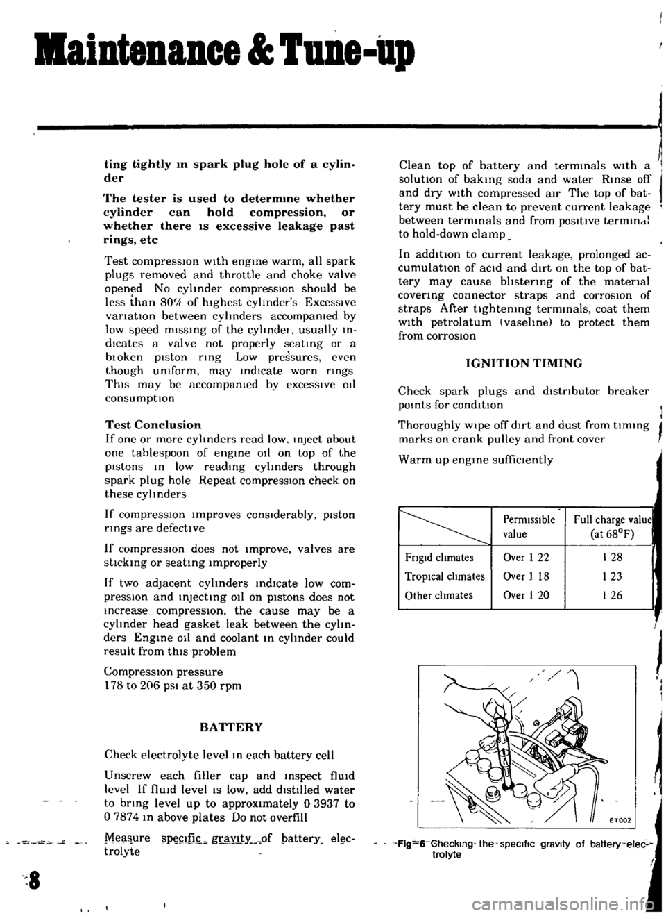
A
pellet
type
thermostat
IS
used
m
the
water
outlet
passage
to
control
the
flow
of
coolant
provldmg
fast
engme
warm
up
and
regulatmg
coolant
temperature
A
wax
pellet
m
the
ther
mo
tat
expands
when
heated
and
contracts
when
cooled
The
pellet
IS
connected
through
a
piston
to
a
valve
and
when
the
pellet
IS
heated
pressure
IS
exerted
agamst
a
rubber
dIaphragm
and
the
valve
opens
As
the
pellet
IS
cooled
the
contractIOn
allows
the
sprmg
to
close
the
valve
Removal
Dram
coohng
water
Remove
radiator
hose
Remove
water
outlet
elbow
Then
take
out
the
thermostat
Inspection
To
test
the
thermostat
for
proper
operatmg
temperature
submerg
he
umt
m
a
contamer
of
water
Heat
the
water
and
observe
the
tem
perature
Measure
temperature
when
the
thermostat
valve
Just
starts
rlsmg
If
thermostat
does
not
operate
at
the
above
specIfied
temperatures
It
must
be
replaced
Installation
When
mstalhng
the
thermostat
apply
adheSIve
Three
Bond
to
both
SIdes
of
the
packmg
for
preventIOn
of
water
leakage
In
stall
the
thermostat
m
reverse
sequence
of
removal
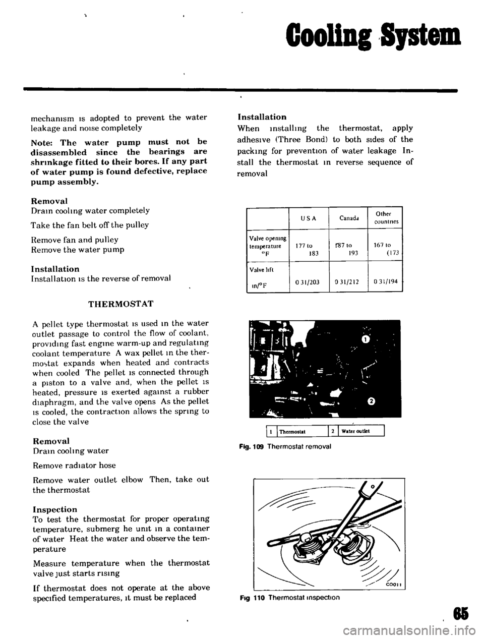
USA
Canadd
Olher
coun
t
nes
Valve
opemng
temperature
177
to
r8710
16710
F
183
193
173
Valve
lIft
O
oF
031
203
031
212
031
194
WI
fL
g
0
I
l
1
L
JI
I
I
I
I
a
J
i
o
wa
r
outlet
EI
Thermostat
Fig
109
Thermostat
removal
FIQ
110
Thermostat
inspection
81
Page 119 of 136

Specifications
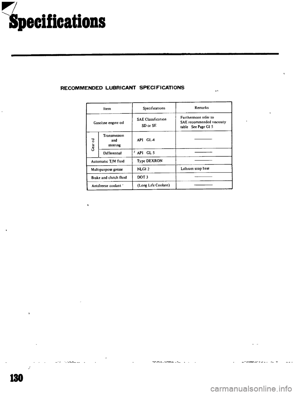
RECOMMENDED
LUBRICANT
SPECI
f
ICATIONS
Item
SpeCificatiOnS
Remarks
SAE
ClaSSIfIcatIon
Furthermore
refer
to
GasolIne
engme
011
SD
or
SE
SAE
recommended
VISCOSity
table
See
Page
GI
5
Transmission
and
API
GL4
0
steenng
l
Dlfferenllal
I
API
GLS
Automallc
TIM
flUId
Type
DEXRON
MultIpurpose
grease
NLGI2
LIthIUm
soap
base
Brake
and
clutch
flUId
OOT3
Antifreeze
coolant
Long
LIfe
Coolant
130