1969 DATSUN B110 oil pressure
[x] Cancel search: oil pressurePage 6 of 136

fable
of
Contents
BODY
WORK
SPECIFICATIONS
I
HOOD
112
SERVICE
DATA
130
Removal
112
ENGINE
134
InstallatIOn
112
General
SpeCificatIOn
134
HOOD
LOCK
112
Tlghtemng
Torque
134
Removal
112
SpeCIficatIOn
135
Adjustment
112
Coohng
System
139
LubncatlOn
114
Fuel
System
140
TRUNK
LID
LOCK
116
Starter
142
Removal
116
Alternator
143
Adjustment
116
Regulator
144
TRUNK
LID
TORSION
BAR
116
Dlstnbutor
145
DOOR
CONSTRUCTION
117
IgnItIOn
Cot
145
WIRING
DIAGRAMS
118
CLUTCH
146
BULB
SPECIFICATIONS
120
NOTES
174
HEADLAMP
121
THERMOMETER
AND
FUEL
METER
122
OIL
PRESSURE
AND
IGNITION
WARNING
LAMPS
126
I
I
t
I
3
Page 8 of 136
ainteDaDee
TUDe
up
VAL
VE
CLEARANCES
Valve
clearance
adjustment
should
be
made
while
engme
IS
stationary
To
adjust
proceed
as
follows
Start
engme
and
run
It
until
It
IS
heated
to
operatIng
temperature
or
at
least
more
than
17S
of
engIne
011
temperature
then
stop
engIne
Rotate
crankshaft
to
bnng
No
1
cylInder
In
top
dead
center
on
ItS
compressIOn
stroke
Remove
valve
rocker
cover
to
gaIn
access
to
valve
operatIng
mechamsm
Adjust
valve
clearance
at
follOWing
four
pOints
while
engIne
IS
still
hot
1
Exhaust
valve
of
No
1
cylinder
2
Intake
valve
of
No
1
cylinder
3
Intake
valve
of
No
2
cylinder
5
Exham
t
valve
of
No
3
cylInder
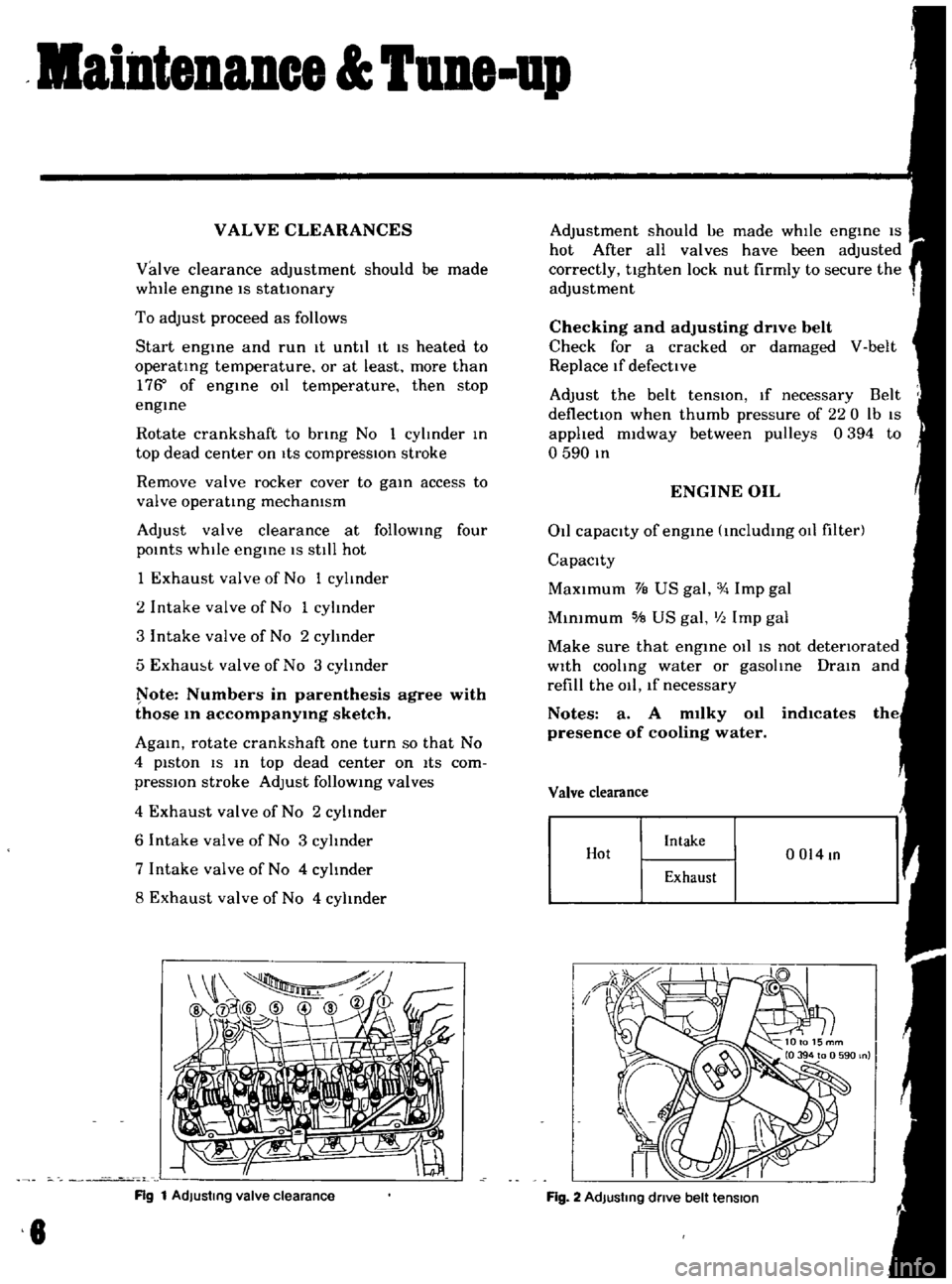
ote
Numbers
in
parenthesis
agree
with
those
10
accompanY1Og
sketch
AgaIn
rotate
crankshaft
one
turn
so
that
No
4
piston
IS
In
top
dead
center
on
ItS
com
pressIOn
stroke
Adjust
follOWIng
valves
4
Exhaust
valve
of
No
2
cylinder
6
Intake
valve
of
No
3
cylinder
7
Intake
valve
of
No
4
cylInder
8
Exhaust
valve
of
No
4
cylinder
Rg
1
AdJustmg
valve
clearance
8
Adjustment
should
ue
made
whIle
engIne
IS
hot
After
all
valves
have
been
adjusted
correctly
tighten
lock
nut
firmly
to
secure
the
adjustment
Checking
and
adjusting
drive
belt
Check
for
a
cracked
or
damaged
V
belt
Replace
If
defective
Adjust
the
belt
tenSIOn
If
necessary
Belt
deflectIOn
when
thumb
pressure
of
220
Ib
IS
applied
midway
between
pulleys
0394
to
o
590
In
ENGINE
OIL
011
capacity
of
engIne
IncludIng
011
filter
Capacity
MaXimum
VB
US
gal
Imp
gal
MInimum
5IB
US
gal
III
Imp
gal
Make
sure
that
engIne
011
IS
not
detenorated
With
cooling
water
or
gasolIne
DraIn
and
refill
the
011
lf
necessary
Notes
a
A
m1lky
011
indlcates
presence
of
cooling
water
Valve
clearance
Hot
Intake
0014
In
Exhaust
Fig
2
AdJustmg
dnve
belt
tension
Page 9 of 136

aintenIDce
une
up
Find
the
cause
for
necessary
corrective
action
b
Oil
with
extremely
low
viscosity
in
dicates
dllutton
with
gasoline
Check
011
level
If
found
below
L
mark
refill
to
H
mark
on
gauge
OIL
FILTER
The
011
filter
IS
of
a
cartndge
type
Check
for
011
leaks
through
gasketed
flange
If
any
leakage
IS
found
retIghten
shghtly
If
nece
sary
replaLe
filter
as
an
assembly
When
mstalhng
an
011
filter
tIghten
by
hand
Note
Do
not
overtighten
011
fIlter
or
oil
leakage
may
result
I
I
Fig
3
Checking
engine
011
level
Oc
OF
I
0
121
20141
30
21
401401
5015BI
I
EGOQl
I
10
20
Fig
4
Protection
concentration
COOLANT
L
L
C
IS
al
ethylene
glycol
base
product
con
tammg
chemical
mhlbltors
to
protect
the
coohng
system
from
rustmg
and
corrosIOn
The
L
I
C
does
not
con
tam
any
glycerme
ethyl
or
methyl
alcohol
It
wIll
not
evaporate
or
bOll
away
and
can
be
used
wIth
either
high
or
low
temperature
thermostat
It
flows
freely
transfers
heat
effiCiently
and
will
not
clog
the
passages
m
the
coohng
system
The
L
L
C
must
not
be
mIxed
wIth
other
products
ThiS
coolant
can
be
used
throughout
the
seasons
of
the
year
Whenever
any
coolant
IS
changed
the
coohng
system
should
be
flushed
and
refilled
wIth
a
new
coolant
Check
the
level
COMPRESSION
Compression
pressure
test
Note
To
test
cylinder
compression
remove
all
spark
plugs
and
hold
tester
fit
Percent
BOllIng
pomt
concen
09
kg
cm2
Freeze
tra
lion
Sea
level
coolmg
sys
protectIon
tern
pressure
30
2210F
2550F
50f
50
2280
F
2610F
31oF
ETO
104
Fig
5
Testing
compressIon
pressure
7
Page 37 of 136
Bmetrlcal
Spt
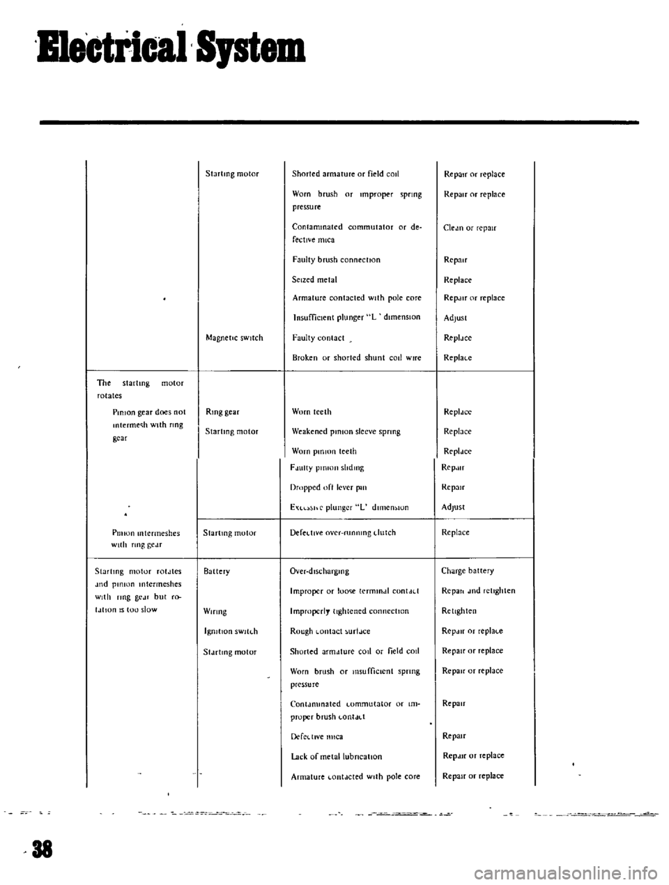
The
startmg
motor
rotates
PinIOn
gear
does
not
mtermec
h
with
flOg
gear
Pillion
mtermeshes
with
nng
gc
lT
Startmg
motor
roldles
Jud
pillion
Intermeshes
With
ring
gc
n
but
r
l
IlIan
IS
tou
slow
Startmg
motor
Magnetic
SWitch
Rmg
gear
Startmg
motor
Startmg
motor
Battery
Wiring
IgnitIOn
sWltl
h
Sldelmg
motor
38
Shorted
armature
or
field
cOIl
Worn
brush
or
Improper
spring
pressure
Contaminated
commutator
or
de
fective
mica
Faulty
brush
connection
Seized
metal
Armature
contacted
With
pole
core
Insufficient
plunger
L
dimenSIOn
Faulty
contact
Brok
en
or
shorted
shunt
call
wire
Worn
teeth
Weakened
pinion
sleeve
sprmg
Worn
pm
IOn
teeth
FJulty
plOlOJl
slldmg
Dropped
oft
lever
pill
EXl
hr
plunger
L
dlll1en
IOn
Defel
tlve
over
runnmg
dutch
Over
dlscharglOg
Improper
or
lome
termmdl
con
Lid
Improperly
tightened
connection
Rough
Lontact
urtJce
Shorted
armdture
COil
or
field
cOIl
Worn
brush
or
I11sufficlCnt
spnng
pressure
Conldmmated
Lomrnutator
or
Im
proper
brush
LonldLl
DercLllVe
nllca
Lack
or
metallubneallon
Armature
Lontdcted
With
pole
core
Repair
or
replace
Repair
or
replace
Cledn
or
repair
Repair
Replace
RepJlr
or
replace
AdjUst
ReplJee
Replace
ReplJee
Replnee
Rcpldce
RepJlr
Rep
m
Adjust
Re
place
Charge
battery
Repall
l11d
retIghten
Rellghten
RepJIr
or
replaLc
Repair
or
replace
Repair
or
replace
Repair
Repau
Repdlf
or
replace
Repair
or
replace
Page 45 of 136
Icnition
Sptem
Ovcrhc
Jtmg
Norm
Jl
i
r
rJ
I
ttr
I
i
V
Carbon
fould
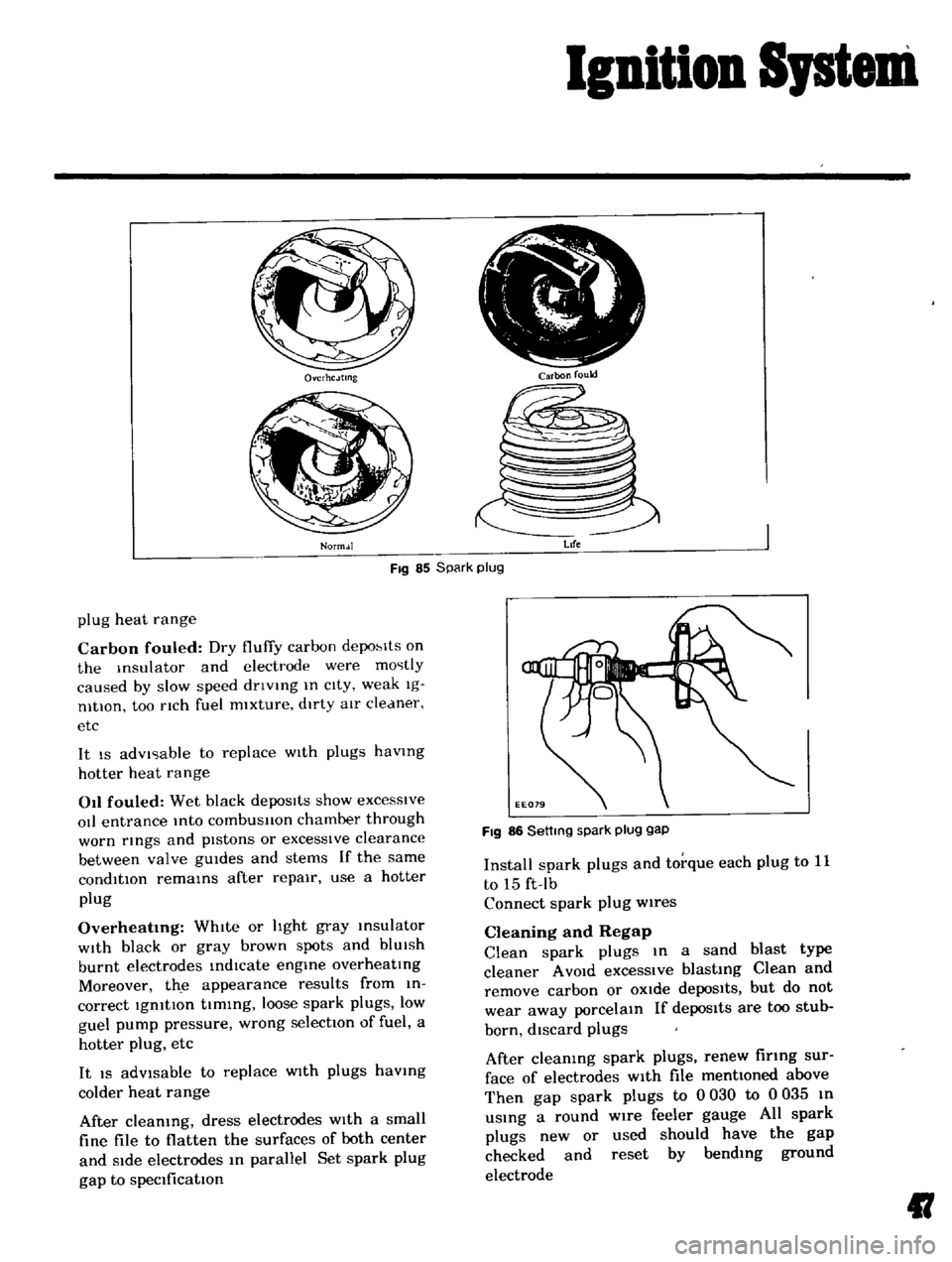
Fig
85
Spark
plug
Life
plug
heat
range
Carbon
fouled
Dry
fluffy
carbon
depo
lts
on
the
Insulator
and
electrode
were
mostly
caused
by
slow
speed
dnvlng
In
cIty
weak
Ig
nltlOn
too
nch
fuel
mixture
dirty
aIr
cleaner
etc
It
IS
advIsable
to
replace
WIth
plugs
havmg
hotter
heat
range
011
fouled
Wet
black
depoSits
show
excesSive
oIl
entrance
Into
combusllon
chamber
through
worn
rmgs
and
pIstons
or
excessIve
clearance
between
valve
gUIdes
and
stems
If
the
same
condition
remams
after
repair
use
a
hotter
plug
Overheatmg
WhIte
or
hght
gray
msulator
WIth
black
or
gray
brown
spots
and
blUIsh
burnt
electrodes
indIcate
engme
overheatIng
Moreover
th
e
appearance
results
from
in
correct
IgnitIon
tIming
loose
spark
plugs
low
guel
pump
pressure
wrong
selectIOn
of
fuel
a
hotter
plug
etc
It
IS
adVisable
to
replace
WIth
plugs
havmg
colder
heat
range
After
cleaning
dress
electrodes
With
a
small
fine
file
to
flatten
the
surfaces
of
both
center
and
Side
electrodes
In
parallel
Set
spark
plug
gap
to
specification
FIg
86
Settmg
spark
plug
gap
Install
spark
plugs
and
torque
each
plug
to
11
to
15
ft
Ib
Connect
spark
plug
wires
Cleaning
and
Regap
Clean
spark
plugs
In
a
sand
blast
type
cleaner
A
VOId
excessIve
blasting
Clean
and
remove
carbon
or
OXide
depoSits
but
do
not
wear
away
porcelain
If
depos1ts
are
too
stub
born
discard
plugs
After
cleaning
spark
plugs
renew
firing
sur
face
of
electrodes
With
file
mentioned
above
Then
gap
spark
plugs
to
0
030
to
0
035
In
uSing
a
round
wire
feeler
gauge
All
spark
plugs
new
or
used
should
have
the
gap
checked
and
reset
by
bending
ground
electrode
II
Page 75 of 136
Brakes
Thoroughly
Wipe
the
bleeder
screw
and
from
any
mud
or
dust
present
so
that
the
outlet
hole
IS
free
from
foreign
matter
Attach
a
VInyl
hose
to
the
wheel
cyhnder
bleeder
screw
Dip
the
end
of
the
VInyl
hose
In
a
Jar
contaInIng
some
brake
flUId
Depress
the
brake
pedal
two
to
three
times
and
keep
the
pedal
fully
depressed
With
the
brake
pedal
fully
depressed
loosen
the
bleeder
screw
exhaust
air
and
rettghten
the
bleeder
screw
qUIckly
Return
the
brake
pedal
slowly
Repeat
the
operatIons
above
Air
WIll
no
longer
come
out
from
the
bleeder
screw
but
brake
flUId
comes
out
When
atr
stIll
eXists
In
brake
flUId
It
appears
whIte
due
to
aIr
bub
ble
Conduct
aIr
bleedIng
on
other
wheel
cyhnders
In
the
same
manner
Note
a
Check
the
reservoir
for
fluid
level
during
bleeding
operation
b
FlUid
withdrawn
in
the
operation
should
not
be
used
refilling
bleeding
again
for
c
When
the
master
cylinder
is
dIsassem
bled
or
replaced
conduct
air
bleeding
on
the
wheel
cylinder
which
is
located
most
near
the
master
cyhnder
d
Ordinarily
air
bleeding
is
performed
in
the
following
sequence
Rear
left
Rear
right
Front
left
Front
right
e
Do
not
return
the
brake
pedal
before
retightening
the
bleeder
screw
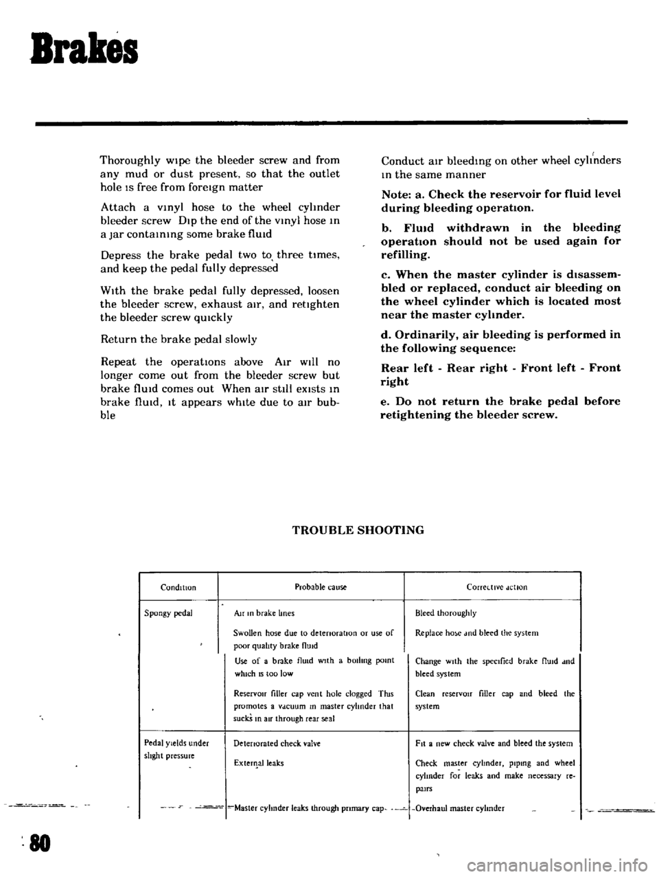
TROUBLE
SHOOTING
Condition
Probable
cause
Corretttve
dellon
Spongy
pedal
Au
In
brake
lines
Bleed
Ihoroughly
Swollen
hose
due
to
detenoratlOn
or
use
of
Replace
ho
e
md
bleed
the
system
poor
qualIty
brake
flUid
Use
of
a
brake
flu
d
wIth
a
bOilIng
pomt
Change
wIth
the
spectlied
brake
flUId
dnd
which
15
too
low
bleed
system
ReservOir
filler
cap
vent
hole
clogged
Tins
Clean
reserVOIr
filler
cap
and
bleed
the
promotes
a
Vdcuum
In
master
cylinder
that
system
suckS
In
air
through
rear
seal
Pedal
Yields
under
Detenorated
check
valve
Fit
a
new
check
valve
and
bleed
the
system
shght
pressure
ExterIlalleaks
Check
master
cyhnder
plpmg
and
wheel
cylInder
for
leaks
and
make
necessary
re
pairs
Master
cyhnder
leaks
through
pnmary
cap
Overhaul
master
cyhnder
80
Page 76 of 136
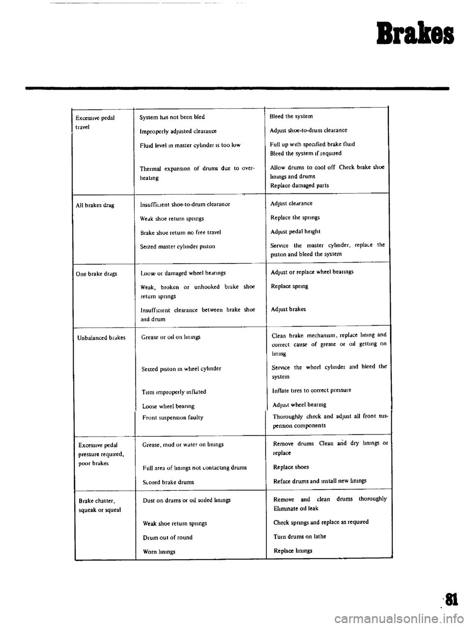
Brakes
Excessive
pedal
travel
All
b
rakes
drag
One
brake
drdgs
Unbalanced
brdkes
Excessive
pedal
pressure
required
poor
brak
es
Brake
chatter
squeak
or
squeal
System
hds
not
been
bled
Improperly
adjusted
clearance
FlUid
level
In
master
cylinder
IS
too
low
Thermal
expansIOn
of
drums
due
to
Qver
hea
lmg
lnsuffiuent
shoe
to
drum
clearance
Weak
shoe
return
springs
Brake
shoe
return
no
free
travel
Seized
master
cylinder
piston
Loose
or
damaged
wheel
bedfmgs
Weak
broken
or
unhooked
brake
shoe
return
spnngs
InsuffiCient
clearance
between
brake
shoe
and
drum
Grease
or
011
on
hnmgs
Seized
piston
In
wheel
cylInder
Tires
Improperly
mtl
lted
Loose
wheel
bearing
Front
suspension
faulty
Grease
mud
or
w
tter
on
Lmmgs
Full
area
of
Immgs
not
Lontaclmg
drums
SLOTed
brake
drums
Dust
on
drums
or
oIl
soLled
Immgs
Weak
shoe
return
springs
Drum
out
of
round
Worn
Itmngs
Bleed
the
system
Adjust
shoe
to
drum
clearance
Full
up
wIth
specIfied
brake
flUId
Bleed
the
system
If
requIred
Allow
drums
to
cool
off
Check
brake
shoe
lImngs
and
drums
Replace
damaged
parts
Adjust
cledrance
Replace
the
spnngs
Adjust
pedal
height
SerVJce
the
master
cyhnder
repla
e
the
pISton
and
bleed
the
syslem
Adjust
Of
replace
wheel
beanngs
Replace
spnng
Adjust
brakes
Clean
brake
mechamsm
repldce
hnmg
and
correct
cause
of
grease
or
011
getllng
on
Lmmg
SerVIce
the
wheel
cyhnder
and
bleed
the
system
Inflate
tires
to
correct
pressure
Adjust
wheel
bearing
Thoroughly
check
and
adlust
all
front
sus
pensIOn
components
Remove
drums
Clean
and
dry
hrongs
or
replace
Replace
shoes
Reface
drums
and
mstall
new
IImngs
Remove
and
clean
drums
thoroughly
ElImmale
oIl
leak
Check
spnngs
and
replace
as
required
Turn
drums
on
lathe
Replace
hrungs
II
Page 91 of 136
Clutch
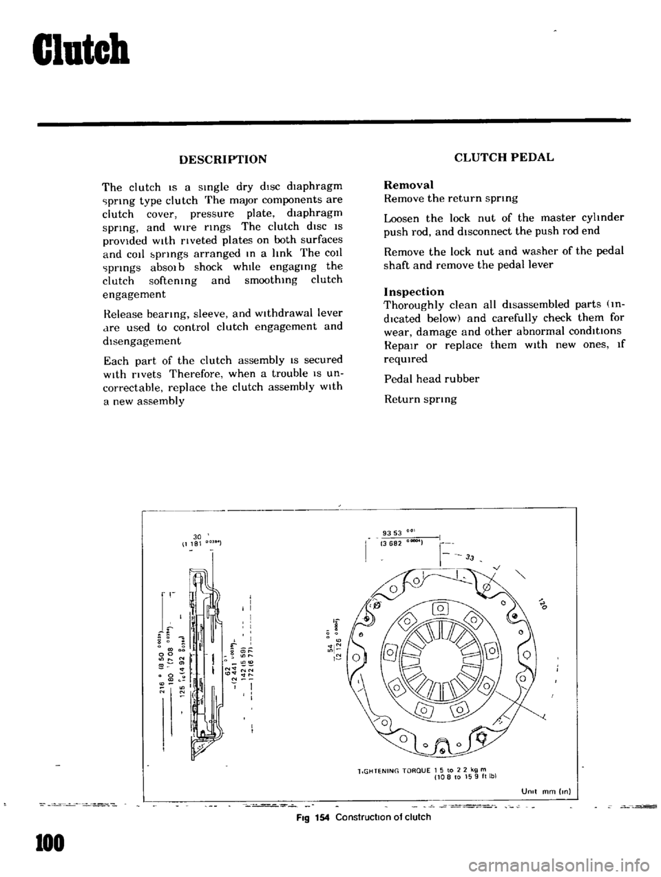
DESCRIPTION
The
clutch
IS
a
sIngle
dry
dIsc
diaphragm
prIng
type
clutch
The
major
components
are
clutch
cover
pressure
plate
diaphragm
sprIng
and
wire
rIngs
The
clutch
diSC
IS
provided
WIth
rIveted
plates
on
both
surfaces
and
cot
bprIngs
arranged
In
a
hnk
The
COIl
prIngs
absOl
b
shock
whIle
engagIng
the
clutch
softemng
and
smoothIng
clutch
engagement
Release
bearIng
sleeve
and
WIthdrawal
lever
dre
used
to
control
clutch
engagement
and
disengagement
Each
part
of
the
clutch
assembly
IS
secured
With
rivets
Therefore
when
a
trouble
IS
un
correctable
replace
the
clutch
assembly
With
a
new
assembly
30
1181
r
I
I
I
I
I
8
1
il
f
0
g
it
l
00
r
O
11
I
N
NN
0
to
lt
lt
ll
l
If
N
O
N
I
I
I
I
FIg
154
Construction
of
clutch
100
CLUTCH
PEDAL
Removal
Remove
the
return
sprmg
Loosen
the
lock
nut
of
the
master
cyhnder
push
rod
and
disconnect
the
push
rod
end
Remove
the
lock
nut
and
washer
of
the
pedal
shaft
and
remove
the
pedal
lever
Inspection
Thoroughly
clean
all
disassembled
parts
m
dlcated
below
and
carefully
check
them
for
wear
damage
and
other
abnormal
conditions
RepaIr
or
replace
them
With
new
ones
If
reqUIred
Pedal
head
rubber
Return
sprIng
9353
3682
00004
lIGHTENING
TORQUE
1
5
to
2
2
kg
m
108
to
159ft
lbl
UOIt
mm
Inl