Page 64 of 136

r
Brakes
Moreover
In
order
to
prevent
brake
squeahng
a
shIm
IS
Inserted
behind
the
pad
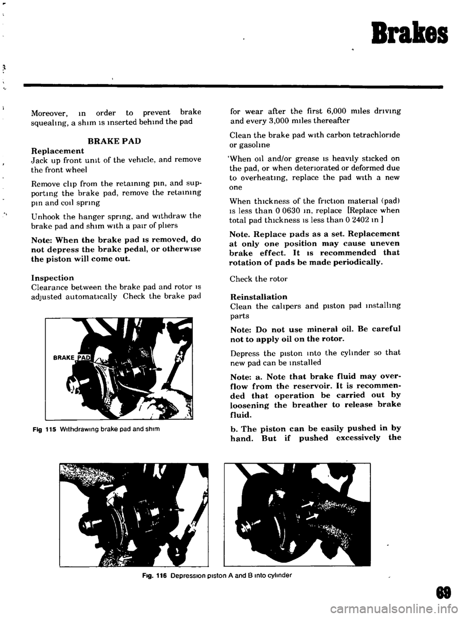
BRAKE
PAD
Replacement
Jack
up
front
UnIt
of
the
vehicle
and
remove
the
front
wheel
Remove
clip
from
the
retaining
pin
and
sup
porting
the
brake
pad
remove
the
retaining
pin
and
COil
spring
Unhook
the
hanger
spring
and
Withdraw
the
brake
pad
and
shim
With
a
pair
of
phers
Note
When
the
brake
pad
IS
removed
do
not
depress
the
brake
pedal
or
otherWise
the
piston
will
come
out
Inspection
Clearance
between
the
brake
pad
and
rotor
IS
adjusted
automatically
Check
the
brake
pad
Fig
115
WIthdraWing
brake
pad
and
shIm
for
wear
after
the
first
6
000
miles
driVing
and
every
3
000
miles
thereafter
Clean
the
brake
pad
With
carbon
tetrachloride
or
gasohne
When
011
and
or
grease
IS
heavIly
stlcked
on
the
pad
or
when
deteriorated
or
deformed
due
to
overheating
replace
the
pad
With
a
new
one
When
thickness
of
the
friction
material
pad
IS
less
than
0
0630
In
replace
Replace
when
total
pad
thIckness
IS
less
than
0
2402
In
Note
Replace
pads
as
a
set
Replacement
at
only
one
position
may
cause
uneven
brake
effect
It
IS
recommended
that
rotation
of
pads
be
made
periodically
Check
the
rotor
Reinstallation
Clean
the
calipers
and
piston
pad
installing
parts
Note
Do
not
use
mineral
oil
Be
careful
not
to
apply
oil
on
the
rotor
Depress
the
pIston
Into
the
cyhnder
so
that
new
pad
can
be
Installed
Note
a
Note
that
brake
fluid
may
over
flow
from
the
reservoir
It
is
recommen
ded
that
operation
be
carried
out
by
loosening
the
breather
to
release
brake
fluid
b
The
piston
can
be
easily
pushed
in
by
hand
But
if
pushed
excessively
the
Fig
116
DepreSSion
piston
A
and
B
Into
cylinder
88
Page 65 of 136

Brakes
groove
of
pIston
goes
insIde
of
seal
as
shown
in
Figure
117
and
the
seal
will
be
damaged
When
the
piston
is
pushed
ex
cesslvely
mto
the
cylinder
remove
the
brake
assembly
disassemble
It
push
out
the
piston
to
the
arrow
direction
as
shown
in
Figure
117
and
reassemble
Install
pad
and
antt
squeal
shim
assemble
the
anti
squeal
spring
and
retaining
pin
and
ecure
them
with
cltp
Install
the
shim
so
that
the
arrow
mark
pOints
the
rotor
forward
rotating
directIOn
Apply
the
COIl
spring
to
the
retaining
pin
which
IS
distanced
from
the
atr
bleeder
111
PlSton
seal
I
2
I
Normal
position
I
Fig
117
Piston
pushIng
In
posllIon
FIg
118
Arrow
mark
on
shim
78
When
the
pad
IS
Installed
depress
the
brake
pedal
several
tl
mes
so
as
to
settle
down
the
pad
In
the
posltton
CALIPER
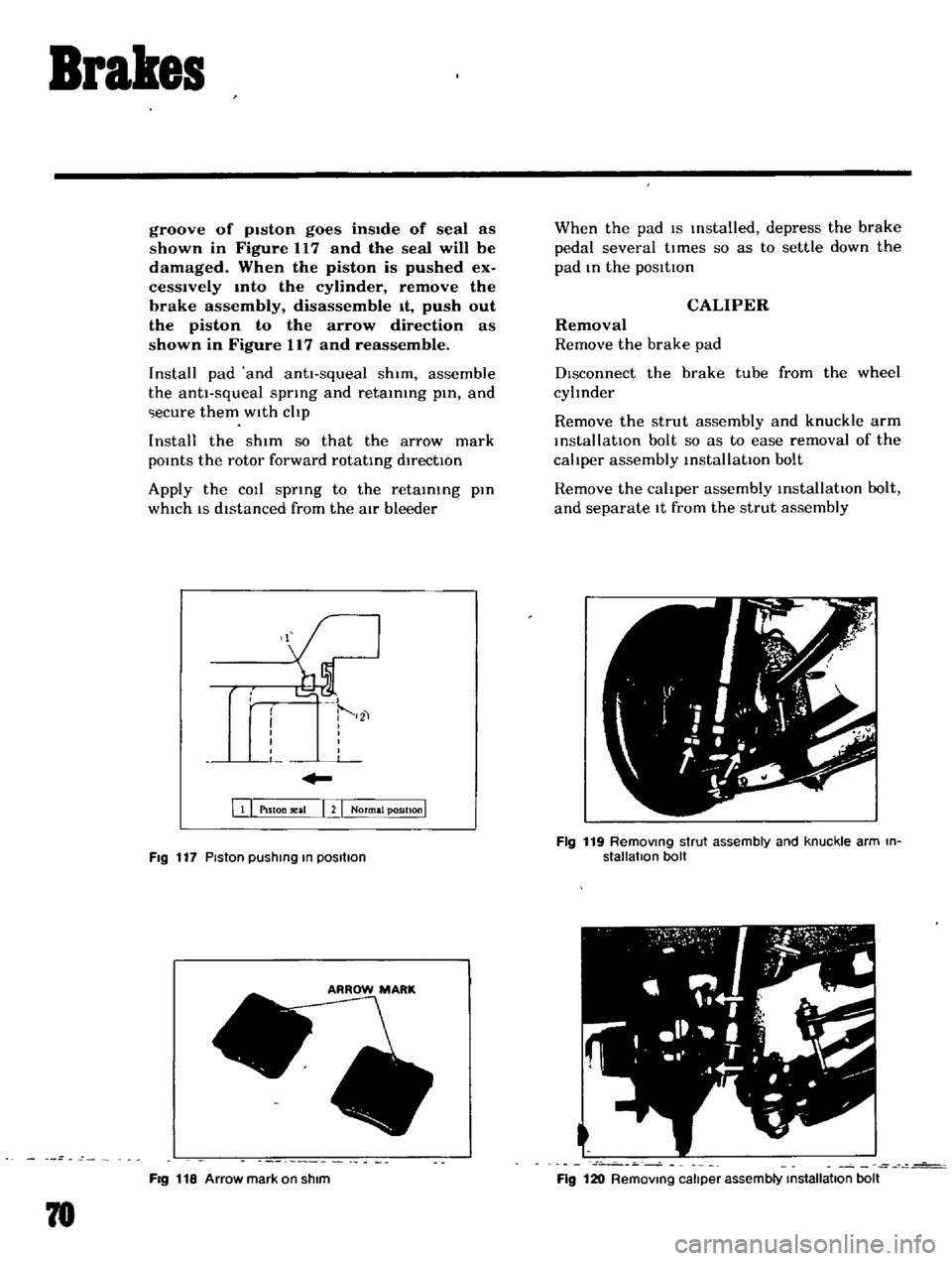
Removal
Remove
the
brake
pad
DIsconnect
the
brake
tube
from
the
wheel
cyltnder
Remove
the
strut
assembly
and
knuckle
arm
installatIOn
bolt
so
as
to
ease
removal
of
the
cahper
assembly
installatIOn
bolt
Remove
the
cahper
assembly
installatIOn
bolt
and
separate
It
from
the
strut
assembly
Fig
119
RemOVing
strut
assembly
and
knuckle
arm
in
stallatIon
bolt
Fig
120
RemOVing
caliper
assembly
Installallon
bolt
Page 67 of 136
Brakes
Note
The
piston
seal
affects
not
only
Ieakmg
but
also
piston
return
For
this
reason
replace
the
piston
seal
even
If
the
damage
IS
minor
Rotor
Check
the
rotor
and
If
It
shows
cOl
e
ex
cesslvely
out
of
round
and
so
forth
recon
ditIOnIng
by
machInIng
l
l
requIred
If
any
ab
normal
condItIOns
such
as
crack
dl
ltortlOn
and
excessIve
deflectIOn
replace
the
rotor
Standard
rotor
thlckne
ls
03740
In
Fig
123
MeaSUring
deflectoon
of
diSC
Fig
124
Installing
bias
ring
mto
piston
A
72
LImIt
of
I
econdltlOntng
lotOl
In
thlcknes
l
o
3307
In
DeflectIOn
of
the
rotor
Below
0
0012
In
Reassembly
Apply
the
rubber
grea
le
to
cylinder
bore
and
Install
the
pIston
seal
Insert
the
bIas
rIng
to
pIston
A
so
that
the
roundl
lh
portIon
of
bIas
ring
comes
to
the
bot
tom
of
pIston
A
PISTON
B
PISTON
A
Fig
125
Piston
A
and
B
Fig
126
Installing
boot
Page 73 of 136

Brakes
ADJUSTMENT
Front
Disc
Brake
Ordinarily
adJu
tment
IS
not
requIred
because
clearance
between
pad
and
rotor
IS
adjusted
automattcally
by
elasttclty
of
the
pIston
seal
I
iJ
1
el
i
C
1
FIg
142
AdJustmg
rear
brake
shoe
clearance
F
J
I
1
I
r
BRAKE
MASTER
CYLINDER
I
tI
Rear
Brake
Jack
up
the
vehicle
and
remove
the
wheel
ApplYing
your
hand
and
tool
from
reverse
side
of
the
brake
diSC
ttghten
the
brake
adjuster
wedge
clockWise
up
to
such
an
extent
that
the
brake
shoe
comes
Into
contact
With
the
brake
drum
Return
the
adjuster
wedge
properly
so
that
the
brake
shoe
IS
separated
from
the
brake
drum
slIghtly
Turn
the
brake
drum
and
If
the
brake
shoe
Interferes
the
brake
drum
readjust
In
ad
dition
depress
the
brake
pedal
and
make
sure
that
the
brake
operates
effecttvely
and
correctly
Loosen
the
stopper
up
to
such
extent
that
the
brake
pedal
stopper
IS
separated
from
the
pedal
arm
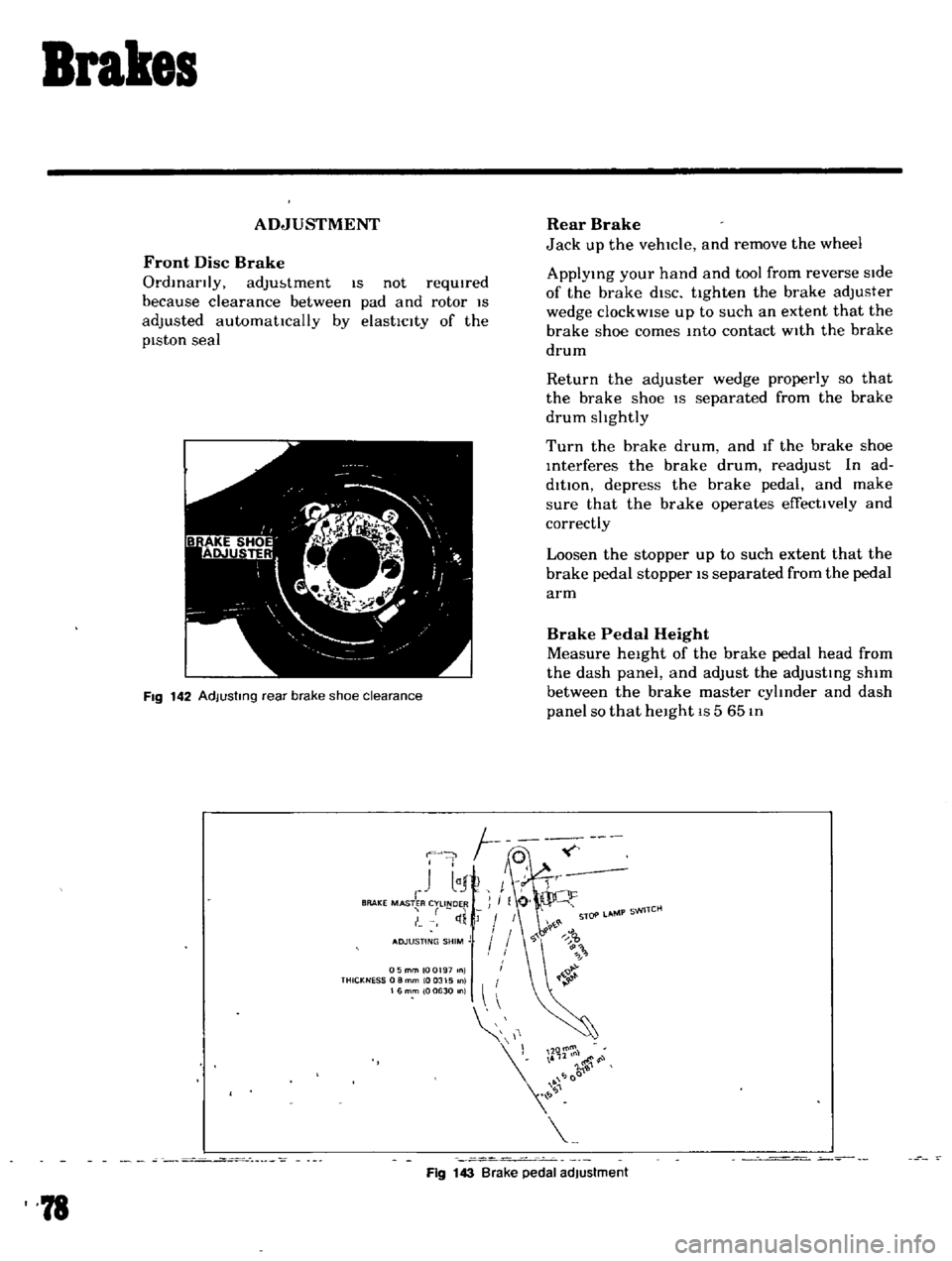
Brake
Pedal
Height
Measure
height
of
the
brake
pedal
head
from
the
dash
panel
and
adjust
the
adjusting
shim
between
the
brake
master
cylInder
and
dash
panel
so
that
height
IS
5
65
In
05mmlOQ197
nl
THICKNESS
0
8
mm
10
0315
0
16mm
100630
n
11
r
l00
Fig
143
Brake
pedal
adjustment
78