1969 DATSUN B110 ESP
[x] Cancel search: ESPPage 2 of 136
lI
I
DATSUN
1200
RANGE
1971
1973
MAINTENANCE
REPAIR
BY
DRAKE
AUTOMOTIVE
EDITORS
Quick
Referencelodel
MAINTENANCE
TUNE
UP
5
STEERING
89
ENGINEERING
13
REAR
DRIVE
ELECTRICAL
SYSTEM
35
SUSPENSION
93
IGNITION
SYSTEM
43
CLUTCH
99
FUEL
SYSTEM
49
TRANSMISSION
103
COOLING
SYSTEM
63
BODY
WORK
111
BRAKES
67
SPECIFICATIONS
129
FRONT
SUSPENSION
83
The
purpose
of
this
manual
IS
to
provide
the
automobile
owner
and
mechanic
with
a
reference
source
with
which
he
can
perform
normal
service
operations
We
endeavor
to
lOcorporate
the
latest
manufacturing
design
changes
and
up
to
date
specifications
at
the
time
of
publication
While
every
effort
IS
made
to
attain
accuracy
the
Publisher
cannot
be
held
responsible
for
manufacturing
changes
typographical
errors
or
omiSSions
Upon
compIling
the
information
contained
herein
we
have
tried
to
be
brief
and
Simple
relvlng
on
the
combination
of
photographs
Illustrations
and
text
to
make
thIS
manual
a
useful
tool
DRAKE
PUBLISHERS
INC
361
PARK
AVENUE
SOUTH
NEW
YORK
NY
10016
Page 10 of 136
aiDtenaDce
TUDe
up
ting
tightly
m
spark
plug
hole
of
a
cylin
der
The
tester
is
used
to
determme
whether
cylinder
can
hold
compression
or
whether
there
IS
excessive
leakage
past
rings
etc
Test
compressIOn
wIth
engme
warm
all
spark
plugs
removed
and
throttle
and
choke
valve
opened
No
cyhnder
compressIOn
should
be
less
than
80
of
highest
cyhnder
s
Excessive
variatIOn
between
cyhnders
accompamed
by
low
speed
missing
of
the
cyllndel
usually
10
dlcates
a
valve
not
properly
seating
or
a
blOken
pIston
ring
Low
preSsures
even
though
umform
may
indIcate
worn
rings
ThIs
may
be
accompamed
by
excessive
011
consumptIOn
Test
Conclusion
If
one
or
more
cyhnders
read
low
Inject
about
one
tablespoon
of
engine
011
on
top
of
the
plstons
In
low
readmg
cyhnders
through
spark
plug
hole
Repeat
compressIOn
check
on
these
cy
II
nders
If
compressIOn
Improves
conSiderably
piston
rings
are
defectIve
If
compressIOn
does
not
Improve
valves
are
stIcking
or
seatIng
Improperly
If
two
adjacent
cyhnders
mdlcate
low
com
pressIOn
and
mjectmg
011
on
pistons
does
not
Increase
compreSSIOn
the
cause
may
be
a
cylInder
head
gasket
leak
between
the
cyhn
ders
Engine
011
and
coolant
In
cylInder
could
result
from
this
problem
CompressIOn
pressure
178
to
206
pSI
at
350
rpm
BATIERY
Check
electrolyte
level
10
each
battery
cell
Unscrew
each
filler
cap
and
Inspect
flUId
level
If
flUId
level
IS
low
add
dIstilled
water
to
bring
level
up
to
approximately
03937
to
07874
In
above
plates
Do
not
overfill
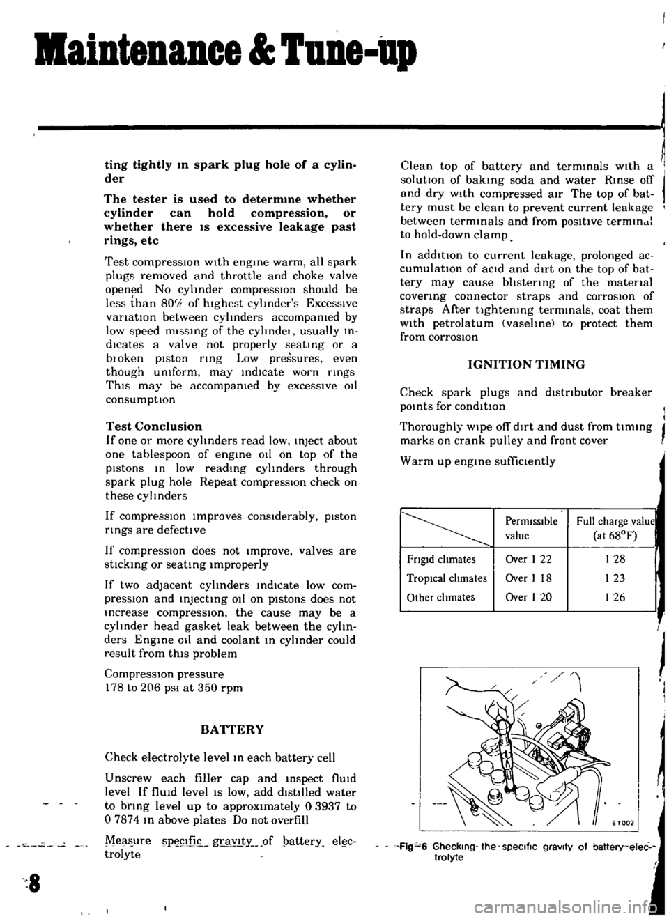
Mea
ure
P
illL
gravlty
of
pattery
el
c
trolyte
8
Clean
top
of
battery
and
terminals
With
a
solutIOn
of
baking
soda
and
water
Rinse
off
and
dry
WIth
compressed
atr
The
top
of
bat
tery
must
be
clean
to
prevent
current
leakage
between
terminals
and
from
poSItive
termlndl
to
hold
down
clamp
In
additIOn
to
current
leakage
prolonged
ac
cumulatIon
of
aCId
and
dirt
on
the
top
of
bat
tery
may
cause
bhstenng
of
the
material
covering
connector
straps
and
corrOSIOn
of
straps
After
tightening
terminals
coat
them
With
petrolatum
vasehnel
to
protect
them
from
corrosIOn
IGNITION
TIMING
Check
spark
plugs
and
dIstributor
breaker
pOints
for
conditIon
I
I
Thoroughly
wipe
off
dIrt
and
dust
from
tlmmg
j
marks
on
crank
pulley
and
front
cover
Warm
up
engine
suffiClently
PermIssIble
Full
charge
value
value
at
68OF
Fngld
chmates
Over
1
22
128
TropIcal
chmates
Over
I
18
123
Other
clunates
Over
1
20
126
j
J
I
ET002
Flg
S
Gheckmg
the
speCific
gravity
of
baltery
elec
trolyte
f
Page 24 of 136
BogiDe
27
00
to
27
05
1063
to
1
0651
1910
to
1940
1910
to
19
40
0752
to
07641
0752
to
0
7641
49951
to
49
964
dl
11
9666
to
1
9671
ALL
MAIN
BEARING
JOURNALS
34
97
to
35
03
1
377
to
1
3791
44
961
to
44
974
dl
1
7701
to
1
7706
ALL
CRANK
PINS
UNIT
mm
m
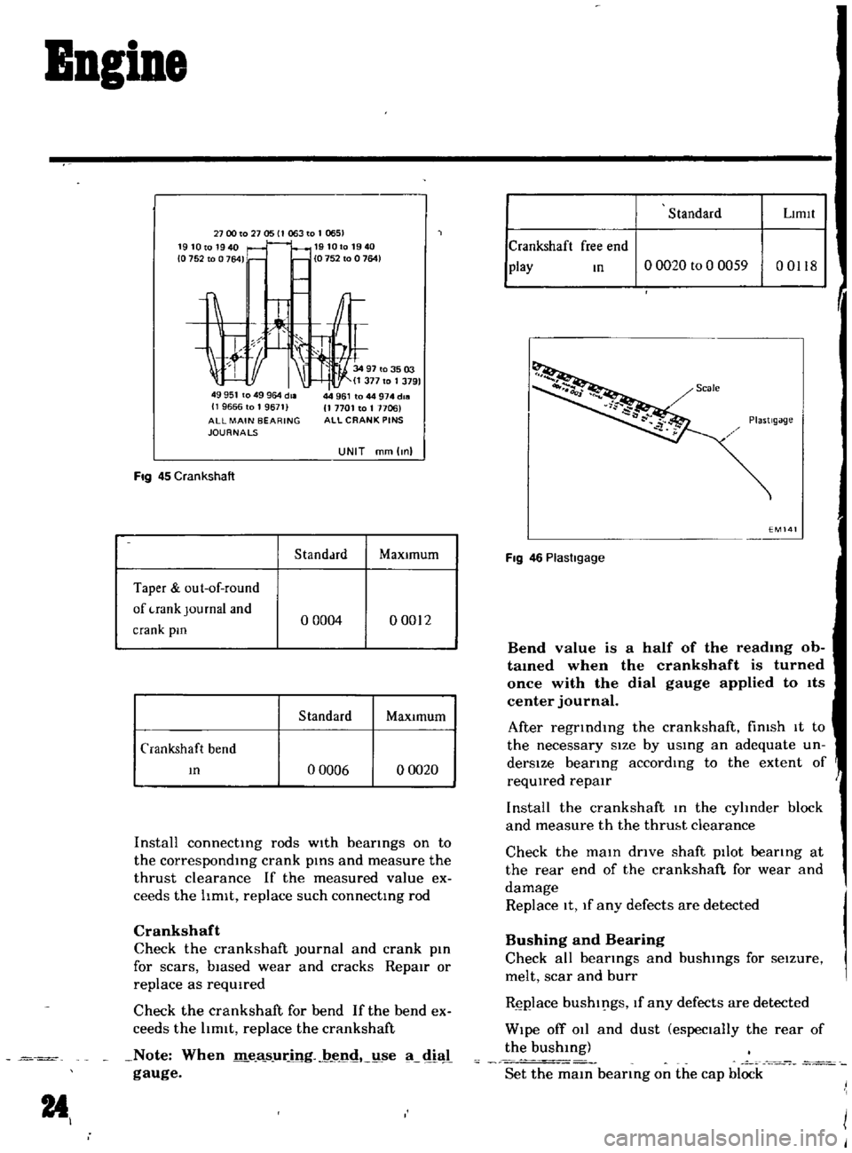
Fig
45
Crankshaft
S
tanddrd
MaXimum
Taper
out
of
round
of
uank
Journal
and
o
0004
00012
crank
pm
Standard
MaxJmum
Crankshaft
bend
m
o
0006
o
0020
Install
connecting
rods
wIth
bearings
on
to
the
corresponding
crank
pinS
and
measure
the
thrust
clearance
If
the
measured
value
ex
ceeds
the
hmlt
replace
such
connecting
rod
Crankshaft
Check
the
crankshaft
Journal
and
crank
pin
for
scars
biased
wear
and
cracks
Repair
or
replace
as
reqUired
Check
the
crankshaft
for
bend
If
the
bend
ex
ceeds
the
hmlt
replace
the
crankshaft
Note
When
me
8
sJlring
jJ
nc
ldtSe
dial
gauge
14
Standard
Llmtl
Crankshaft
free
end
play
m
o
0020
to
0
0059
00118
EM141
Fig
46
Plasllgage
Bend
value
is
a
half
of
the
readmg
ob
tamed
when
the
crankshaft
is
turned
once
with
the
dial
gauge
applied
to
Its
center
journal
After
regrInding
the
crankshaft
fimsh
It
to
the
necessary
size
by
uSing
an
adequate
un
derSize
bearing
according
to
the
extent
of
reqUIred
repair
Install
the
crankshaft
In
the
cyhnder
block
and
measure
th
the
thruht
clearance
Check
the
main
drIve
shaft
pilot
beating
at
the
rear
end
of
the
crankshaft
for
wear
and
damage
Replace
It
1f
any
defects
are
detected
Bushing
and
Bearing
Check
all
bearIngs
and
bushings
for
seIzure
melt
scar
and
burr
Rgj
Jlace
bushings
If
any
defects
are
detected
Wipe
off
011
and
dust
especially
the
rear
of
the
bushing
Set
the
main
bearing
on
the
cap
block
Page 27 of 136
Bogine
Note
Set
the
locate
plate
so
as
the
LOWER
mark
comes
to
the
engine
bot
tom
side
Set
the
maIn
bearIngR
on
theIr
posItIOns
on
the
cylinder
block
Notes
a
The
center
bearmg
No
3
bearmg
is
a
flanged
type
for
thrust
force
b
Two
lOner
bearmgs
No
2
and
No
4
are
of
the
same
type
c
The
front
bearmg
No
1
IS
the
same
type
as
the
rear
bearmg
No
5
d
All
bearings
except
for
No
I
bearing
are
interchangeable
between
upper
and
lower
bearings
Apply
engIne
OIl
to
the
mam
bearIng
surfaces
on
both
sIdes
of
the
cyltnder
block
and
cap
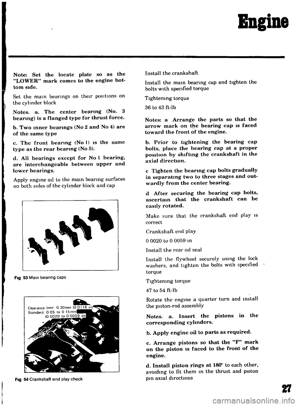
Fig
53
Mam
bearing
caps
Fig
54
Crankshaft
end
play
check
Install
the
crankshaft
Install
the
mam
bearmg
cap
and
tighten
the
bolts
with
specified
torque
Tlghtemng
torque
36
to
43
ft
Ib
Notes
a
Arrange
the
parts
so
that
the
arrow
mark
on
the
bearing
cap
IS
faced
toward
the
front
of
the
engine
b
Prior
to
tightening
the
bearing
cap
bolts
place
the
bearing
cap
at
a
proper
posItIon
by
shlftmg
the
crankshaft
in
the
axial
direction
c
Tighten
the
bearmg
cap
bolts
gradually
in
separatmg
two
to
three
stages
and
out
wardly
from
the
center
bearing
d
After
securing
the
bearing
cap
bolts
ascertam
that
the
crankshaft
can
be
easily
rotated
Make
sure
that
the
crankshaft
end
play
IS
correct
Crankshaft
end
play
o
0020
to
0
0059
In
I
nstalI
the
rear
011
seal
Install
the
flywheel
securely
USIng
the
lock
washers
and
tighten
the
bolts
with
specIfied
torque
Tlghtemng
torque
47
to
54
ft
Ib
Rotate
the
engine
a
quarter
turn
and
mstall
the
piston
rod
assembly
Notes
a
Insert
the
pistons
in
the
corresponding
cyhnders
b
Apply
engine
oil
to
parts
as
required
c
Arrange
pistons
so
that
the
F
mark
on
the
piston
IS
faced
to
the
front
of
the
engine
d
Install
piston
rings
at
18
Y
to
each
other
avoIdIng
to
fit
them
In
the
thrust
and
pIston
pIn
aXial
directIOns
27
Page 30 of 136
BDgiDe
Install
the
new
011
seal
to
the
front
cover
The
front
cover
011
seal
should
be
replaced
when
the
front
cover
IS
disassembled
Install
the
front
cover
applYing
the
seahng
agent
to
both
surfaces
of
the
gasket
Tlghtemng
torque
36
to
5
1
ft
lb
Install
the
ot
strainer
and
the
011
pan
uSing
the
gasket
Apply
seahng
agent
on
both
surfaces
of
the
gasket
especIally
on
the
front
and
rear
por
tlOns
of
the
011
pan
011
pan
tlghtemng
torque
2
9
to
4
3
ft
lb
Invert
the
engine
and
Install
the
cyhnder
head
assembly
and
gasket
Note
Apply
sealing
agent
overall
the
cylinder
block
surface
Place
the
gasket
on
It
and
apply
sealing
agent
to
the
gasket
top
Tighten
the
cylinder
head
bolts
to
the
peclfied
torque
Cylmder
bloLk
Side
Stecl
heet
Sealmg
agent
not
required
Cylinder
head
Side
Jomt
sheet
Remarks
Install
WIthout
applymg
sealing
agent
Be
careful
not
to
damage
the
push
rod
Side
because
thIS
SIde
has
prevIOusly
been
provIded
WIth
sealing
agent
J
30
v
o
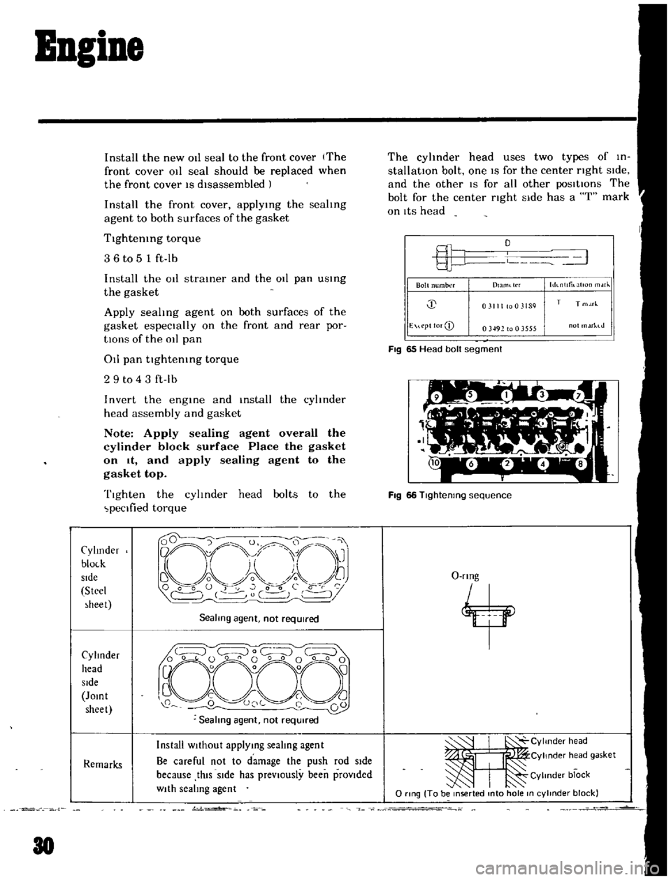
The
cyhnder
head
uses
two
types
of
in
stallatIOn
bolt
one
IS
for
the
center
nght
SIde
and
the
other
IS
for
all
other
posItIOns
The
bolt
for
the
center
nght
Side
has
a
I
mark
on
ItS
head
L
1
Bolt
number
hh
nlltilatlOn
rJ
Dlaml
tl
f
j
031111003189
T
T
1M
E
u
pt
lor
CD
03492
to
0
3555
ot
rhJ
FIg
65
Head
bolt
segment
Fig
66
Tlghtenmg
sequence
O
rmg
4
ItI
CYlmder
head
Cylinder
h
ad
gasket
Cylinder
block
o
rtng
To
be
mserted
mto
hole
m
cylmder
block
Page 56 of 136
Fuel
Sptem
In
removIng
Injector
weight
piston
return
sptlng
and
ball
care
should
be
exercIsed
to
prevent
them
from
beIng
scattered
and
lost
To
check
the
accelerator
pump
the
pump
cover
IS
removed
Be
careful
not
to
lose
the
return
spring
and
mlet
valve
bal
prOVided
at
the
lower
part
of
the
piston
dUring
dIsassembly
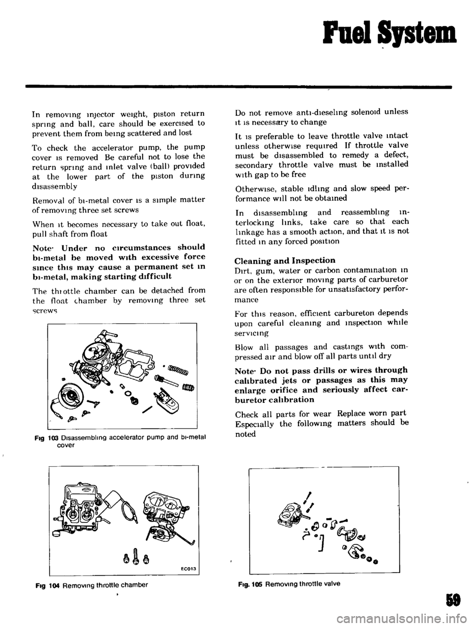
Removal
of
bl
metal
cover
IS
a
sImple
matter
of
removmg
three
set
screws
When
It
becomes
necessary
to
take
out
float
pull
shaft
from
float
Note
Under
no
C1rcumstances
should
bl
metaI
be
moved
with
excessive
force
Since
this
may
cause
a
permanent
set
In
b1
metal
making
starting
d1fficuIt
The
thlottle
chamber
can
be
detached
from
the
float
hamber
by
removmg
three
set
screws
Fig
103
Disassembling
accelerator
pump
and
bl
metal
cover
1
EC013
Fig
104
RemOVing
throttle
chamber
Do
not
remove
antl
dlesehng
solenOId
unless
It
IS
necessary
to
change
It
IS
preferable
to
leave
throttle
valve
mtact
unless
otherWise
reqUIred
If
throttle
valve
must
be
dIsassembled
to
remedy
a
defect
secondary
throttle
valve
must
be
Installed
wIth
gap
to
be
free
OtherWise
stable
Idlmg
and
slow
speed
per
formance
Will
not
be
obtamed
In
dlsassembhng
and
reassembhng
in
terlockIng
hnks
take
care
so
that
each
lInkage
has
a
smooth
action
and
that
It
IS
not
fitted
m
any
forced
posltton
Cleaning
and
Inspection
Dirt
gum
water
or
carbon
contammatIon
m
or
on
the
exterior
movmg
parts
of
carburetor
are
often
responsible
for
unsattsfactory
perfor
mance
For
thiS
reason
effiCient
carbureton
depends
upon
careful
cleamng
and
InspectIOn
whtle
servlcmg
Blow
all
passages
and
castmgs
wIth
com
pressed
aIr
and
blow
off
all
parts
unttl
dry
Note
Do
not
pass
drills
or
wires
through
calibrated
jets
or
passages
as
this
may
enlarge
orifice
and
seriously
affect
car
buretor
calibration
Check
all
parts
for
wear
Replace
worn
part
EspeCially
the
followmg
matters
should
he
noted
I
1
Q
o
Fig
105
RemOVing
throttle
valve
18
Page 80 of 136
Pront
Suspension
Shock
When
the
fronl
wheels
are
travel
Img
over
bumpy
roads
the
play
of
the
steenng
linkage
IS
transnutted
to
the
steering
wheel
This
IS
especially
notice
able
when
travellmg
rough
road
Shlmmymg
Abnormal
VIbratIOns
of
the
front
suspensIOn
group
and
lhe
whole
sleenng
hnkage
which
occur
when
a
specific
speed
IS
attamed
VehIcle
pulls
to
right
or
left
Vhen
driVing
With
hands
off
the
steering
wheel
over
a
flat
road
the
vehicle
gently
swerves
to
nght
or
lefl
Note
A
defective
rear
suspenSion
may
also
be
the
cause
of
tillS
trouble
and
therefore
see
also
the
chapter
dealing
With
the
rear
suspenSion
InstabilIty
of
vehIcle
Stoff
steering
wheel
checking
up
procedure
Jack
up
fronl
wheels
detach
the
steenng
g
nd
o
ra
h
ste
g
h
J
andk
88
Worn
fittmg
transverse
hnk
bushmgs
Insufficiently
tlghten
d
steenng
gear
housmg
Wear
of
steenng
hnkage
Worn
suspensIOn
ball
Jomt
E
xcesslve
backlash
due
to
improper
ad
Justment
of
the
ret
uner
parts
Worn
column
beanng
weakened
column
beanng
spnng
or
loose
clamp
MalfunctIOn
of
shock
absorber
inSIde
the
strut
or
loose
mstdllatJon
bolts
Unbalance
ofvehtcle
level
Improper
au
pressure
of
tire
or
msuf
ficlent
hghtenmg
of
wheel
nuts
Difference
In
height
of
nght
and
left
lIre
treads
Incorrect
adjustment
or
abraSIOn
of
front
wheel
beanng
Collapsed
or
tWisted
front
sprmg
Incorrect
wheel
alIgnment
Incorrect
brake
adjustment
bmdmg
Worn
rubber
bushmgs
for
transverse
link
and
tensIOn
rod
Deformed
steering
linkage
and
suspensIOn
lInk
Unbalanced
vehicle
level
Improper
au
pressure
of
tire
Worn
rubber
bushmgs
for
tmnsverse
Imk
and
tensIOn
rod
Incorrect
wheel
alignment
Worn
or
deformed
steenng
hnkage
and
suspensIOn
link
Incorrect
adjustment
of
steenng
gear
Deformed
unbalanced
wheel
Improper
au
pressure
of
lire
InsuffiCient
lubricants
or
nuxmg
Im
pun
ties
m
sleenng
linkage
or
exceSSively
o
steenng
Imkage
Replace
Rellghten
Replace
defective
p
uts
Replace
Adjust
correctly
Check
and
repdlT
cor
rectly
Replace
or
relighlen
Correl
t
the
unbaldnl
e
Adjust
or
tighten
Replace
tlTes
Adjust
or
replal
c
Repldcc
Adjust
Adlusl
Repl
n
e
Repldc
e
Correcl
the
unbdJdlKe
Adjust
AdlU
t
Adjust
Replace
AdJusl
Correcl
or
replaf
e
Adlust
Repl
msh
grease
or
re
place
the
pa
rt
Page 84 of 136
Steering
DESCRIPTION
mtles
and
replenIsh
recommended
011
as
reqUIred
The
steetlng
linkage
should
be
greased
up
WIth
wheel
bearing
grease
every
30
000
mtles
The
steering
ystem
consIsts
of
reclrculatmg
ball
type
gear
box
and
parallelogram
linkage
These
y
tems
gIve
good
respon
e
light
han
dlmg
and
utmost
durabIlity
Moreover
the
teermg
linkage
IS
eqUIpped
With
a
torsIOn
rubber
sy
tem
Idler
arm
whIch
absorbs
shock
from
the
wheel
RECOMMENDATIONS
Check
the
lubricant
of
gear
box
every
6
000
Due
to
the
need
for
a
large
number
of
specIal
tools
and
alignment
eqUIpment
It
IS
recom
mended
that
repairs
to
the
steering
com
ponents
be
left
to
a
completely
eqUIpped
shop
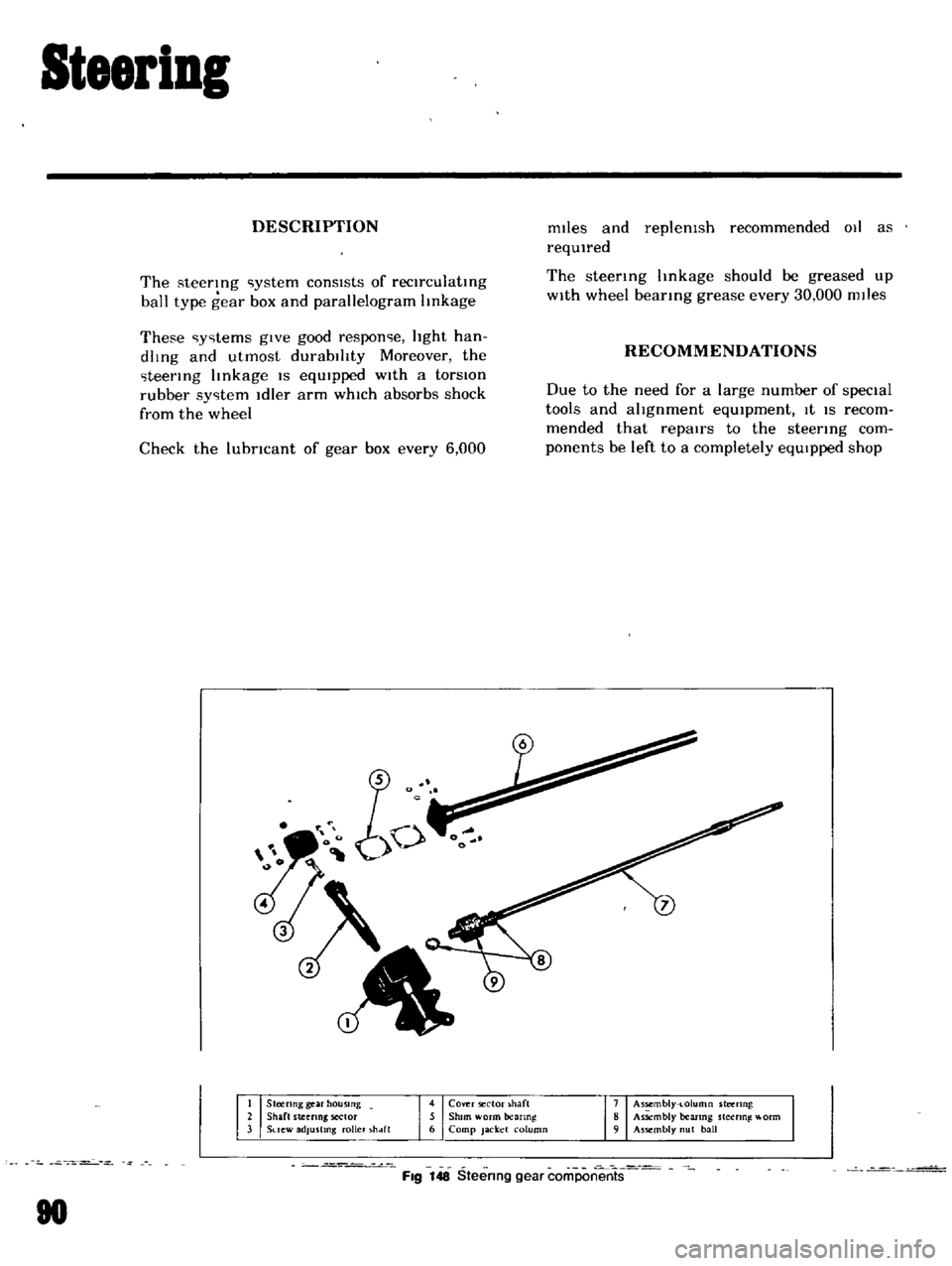
Steenng
gear
housing
Shaft
steeling
sector
Suew
adjusting
roller
hdft
4
Cover
ector
haft
5
Shim
worm
anng
6
Camp
Jacket
column
7
Assembly
t
olumn
steering
8
As
mbly
bearmg
steering
l
orm
9
Assembly
ut
ball
Fig
148
Steering
gear
coriiPon
rrts
80