1969 DATSUN B110 automatic transmission
[x] Cancel search: automatic transmissionPage 4 of 136

able
of
Contents
MAINTENANCE
TUNE
UP
DIsassembly
32
InspectIOn
RepaIr
33
VALVE
CLEARANCES
6
AdJustmg
Regulator
33
ENGINE
OIL
6
Assembly
33
OIL
FILTER
7
COOLANT
7
COMPRESSION
7
ELECTRICAL
SYSTEM
BATTERY
8
IGNITION
TIMING
8
STARTER
36
DIstributor
Breaker
Pomt
9
Removal
37
Condenser
9
InstallatIOn
37
Spark
Plugs
9
Trouble
Shootmg
37
Carburetor
9
ALTERNATOR
36
Idle
LImIter
Cap
10
Removal
37
Dash
Pot
automatic
transmISSIOn
11
InstallatIOn
37
model
only
11
REGULATOR
39
Carburetor
Return
Sprmg
11
DeSCriptIOn
39
Fuel
Filter
11
Trouble
Shootmg
40
ENGINE
IGNITION
SYSTEM
DESCRIPTION
14
DISTRIBUTOR
44
REMOVAL
14
ConstructIOn
44
INSTALLATION
14
Checkmg
and
Adjustment
44
CLEANING
INSPECTION
14
SP
ARK
PLUGS
46
DISASSEMBL
Y
14
DeSCriptIOn
46
INSPECTION
REPAIR
18
InspectIOn
46
PreparatIOn
18
Cleamng
Regap
47
Cyltnder
Head
18
Valve
Assembly
18
Valve
Spnng
19
Valve
Rocker
Shaft
Rocker
Arm
19
FUEL
SYSTEM
Valve
LIfter
Push
Rod
20
Camshaft
Camshaft
Bearmg
20
FUEL
FILTER
50
Valve
Tlmmg
20
DESCRIPTION
50
Cyltnder
Block
21
REMOVAL
50
PIston
Piston
Pm
Plsto
LRmg
21
INSTALLATION
50
Connectmg
Rod
23
FUEL
PUMP
50
Crankshaft
24
DeSCriptIOn
50
Bushmg
Bearing
24
Testmg
51
Crankshaft
Sprocket
Removal
DIsassembly
52
Camshaft
Sprocket
25
InspectIOn
52
Flywheel
25
Assembly
52
ASSEMBL
Y
25
CARBURETOR
52
PrecautIOn
25
DeSCription
52
Cyltnder
Head
25
Adjustment
53
PIston
ConnectIng
Rod
26
Removal
58
Engme
26
DIsassembly
58
OIL
PUMP
32
Cleanmg
InspectIOn
59
Removal
Engme
m
vehicle
32
Assembly
InstallatIOn
60
I
Page 12 of 136
aiDteDaDce
UDe
up
Adjust
throttle
adjusting
screw
so
that
engme
speed
1S
800
rpm
m
N
positIOn
for
automatic
transmIssIOn
Check
IgnitIOn
tlmmg
If
necessary
adjust
1t
to
the
specIficatIOns
IgnitIOn
timing
50
800
rpm
Adjust
Idle
adjusting
screw
so
that
CO
percen
tage
IS
1
5
t0
5
ff
Repeat
the
adjustments
as
desctlbed
In
steps
3
above
so
that
CO
percentage
IS
15
t0
5
ff
at
800
rpm
Cautions
a
On
automatic
transmission
equipped
model
check
must
be
done
in
the
D
position
Be
sure
to
apply
parking
brake
and
to
lock
both
front
and
rear
wheels
wIth
wheel
chocks
b
Hold
brake
pedal
while
stepping
down
on
accelerator
pedal
Otherwise
car
will
rush
out
dangerously
On
automatic
transmISSIOn
eqUIpped
model
make
sure
that
the
adjustment
has
been
made
wIth
the
selector
lever
In
N
posItion
And
then
check
the
specificatIOns
with
the
lever
In
D
posItion
Insure
that
CO
percent
and
Idle
speed
are
as
follows
Idle
rpm
650
Idle
Limiter
Cap
CO
percentage
Do
not
remove
this
Idle
hm1ter
cap
unless
necessary
If
this
Unit
IS
removed
It
IS
I
with
lever
In
D
PoSitIOn
1
5
t
0
5
k
necessary
to
re
adJust
It
at
the
time
of
In
If
necessary
adjust
by
progIesslvely
turmng
stallatlon
To
adjust
proceed
as
follows
throttle
adJustlng
screw
and
Idle
adJustmg
Make
sure
that
the
percentage
oLCO
contents
screw
until
correct
adjustments
are
made
satisfies
the
specifications
I
I
I
I
J
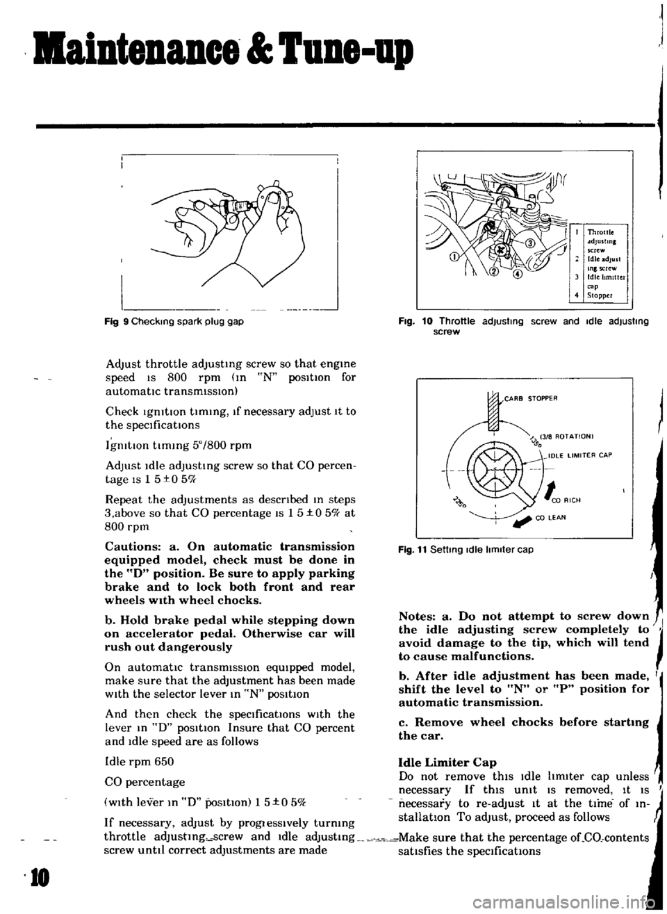
Fig
9
Checking
spark
plug
gap
10
Throttle
sdJustlnl
screw
Idle
adjust
Inlscrew
Idle
Itmlttc
r
cap
4
Stopper
Fig
10
Throttle
adjusting
screw
and
Idle
adjusting
screw
CARB
STOPPER
Fig
11
Setting
Idle
limiter
cap
Notes
a
Do
not
attempt
to
screw
down
the
idle
adjusting
screw
completely
to
JI
avoid
damage
to
the
tip
which
will
tend
to
cause
malfunctions
b
After
idle
adjustment
has
been
made
I
shift
the
level
to
N
or
P
position
for
automatic
transmission
c
Remove
wheel
chocks
before
startmg
the
car
Page 13 of 136
aiDtenuce
TUDe
up
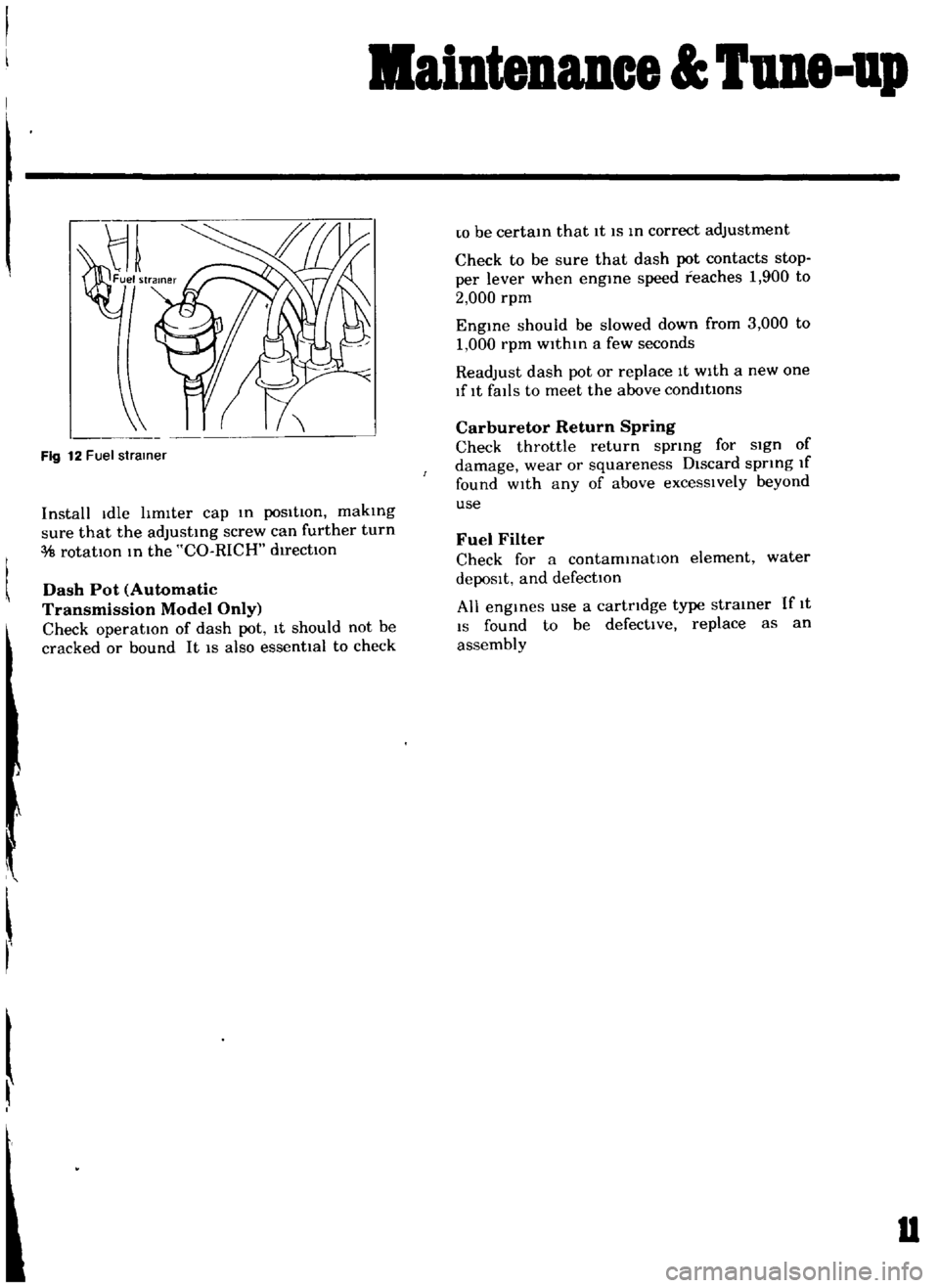
Fig
12
Fuel
strainer
Install
Idle
hmlter
cap
m
posItion
makmg
sure
that
the
adJustmg
screw
can
further
turn
rotatIOn
m
the
CO
RICH
d1rectlOn
Dash
Pot
Automatic
Transmission
Model
Only
Check
operation
of
dash
pot
It
should
not
be
cracked
or
bound
It
IS
also
essenttal
to
check
r
w
be
certam
that
It
IS
m
correct
adjustment
Check
to
be
sure
that
dash
pot
contacts
stop
per
lever
when
engme
speed
reaches
1
900
to
2
000
rpm
Engme
should
be
slowed
down
from
3
000
to
1
000
rpm
within
a
few
seconds
Readjust
dash
pot
or
replace
It
with
a
new
one
lflt
falls
to
meet
the
above
condItions
Carburetor
Return
Spring
Check
throttle
return
sprmg
for
sign
of
damage
wear
or
squareness
Discard
spring
If
found
wIth
any
of
above
excessIvely
beyond
use
Fuel
Filter
Check
for
a
contammatlOn
element
water
depoSIt
and
defection
All
engmes
use
a
cartridge
type
strainer
If
1t
IS
found
to
be
defective
replace
as
an
assembly
u
Page 15 of 136
Bngine
WIres
for
accelerator
and
choke
The
operatIOn
Will
be
carned
out
more
easily
by
removing
the
a1r
cleaner
Lift
up
the
engine
toward
the
front
INST
ALLA
TION
Install
the
engine
In
reverse
sequence
of
removal
Disconnecting
clutch
wire
on
nght
hand
dnve
model
On
left
hand
dnve
model
disconnect
hydraulIc
line
from
the
clutch
slave
cylInder
DIsconnect
the
clutch
WIre
at
the
JXlrtlOn
of
the
wIthdrawal
lever
Remove
the
exhaust
front
tube
Disconnect
the
the
cable
to
the
back
up
lamp
SWItch
D1sconnect
the
speedometer
cable
Remove
the
propeller
shaft
Remove
four
bolts
used
In
the
differential
carner
SIde
and
Withdraw
the
propeller
shaft
Remove
the
shift
lever
Model
With
remote
control
shIft
lever
Disconnect
the
remote
control
rod
at
the
JXlr
tlOn
of
transmiSSIOn
outer
lever
and
remove
the
remote
control
rod
Model
With
floor
Sh1ft
lever
Remove
the
boot
WIthdraw
the
lock
pin
and
remove
the
lever
The
operatIOn
IS
carned
out
In
the
passenger
compartment
Model
With
automatic
transmiSSIOn
Remove
pinS
from
both
ends
of
the
cross
shaft
and
remove
the
shIft
rod
Suspend
the
engine
With
wire
Remove
the
front
engine
mounting
installation
nuts
Remove
the
rear
engine
mounting
installation
nuts
When
removing
the
engine
mounting
in
stallation
nuts
be
sure
to
apply
a
Jack
beneath
the
transmiSSIOn
CLEANING
AND
INSPECTION
Clean
the
engine
thoroughly
before
disassem
bly
Before
cleaning
the
engine
remove
the
l
electncal
parts
and
plug
up
the
carburetor
air
horn
to
aVOid
intrusIOn
of
foreign
matter
The
engine
extenor
Check
the
covers
and
bolts
for
breakage
rust
damage
and
loss
CylInder
block
Check
thoroughly
the
water
Jacket
for
cracks
and
breakage
Clutch
hOUSing
Check
for
cracks
011
pan
Check
for
excessive
rust
DISASSEMBLY
Mount
engine
assembly
on
engine
stand
Remove
the
engine
mounting
bracket
R
H
Side
Install
the
engine
attachment
Mount
the
engine
on
the
stand
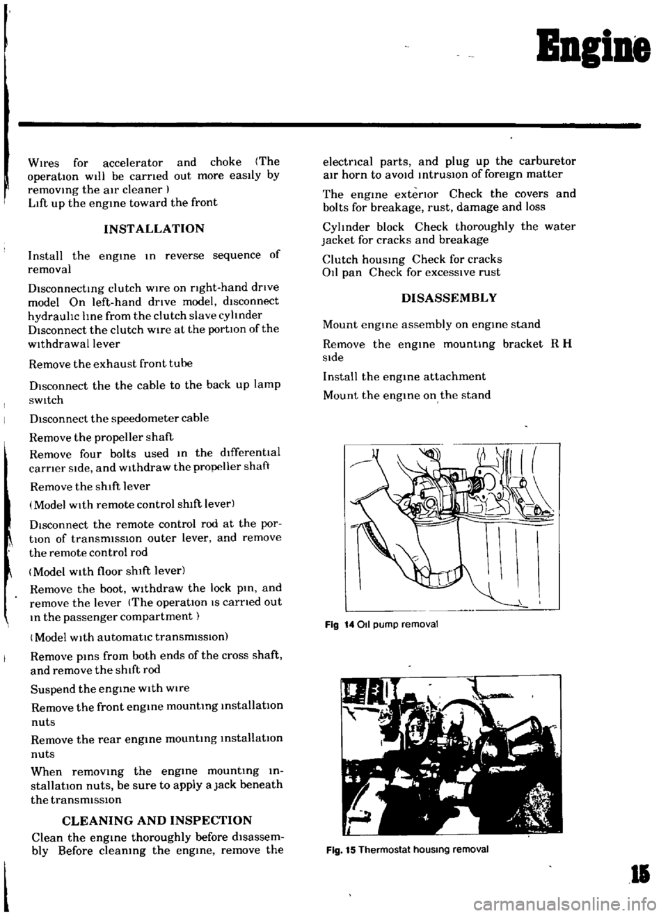
Fig
14011
pump
removal
Fig
15
Thermostat
hOUSing
removal
II
Page 50 of 136
Fuel
Sptem
The
power
valve
mechanIsm
IS
of
a
vacuum
actuated
boost
type
and
Improves
hIgh
speed
drivIng
The
throttle
opener
control
system
Incor
porates
a
servo
diaphragm
The
servo
dIaphragm
helps
open
the
throttle
valve
at
a
decreasIng
speed
so
as
to
reduce
the
emISSIOn
of
hydrocarbons
to
a
minImum
An
antI
dlesehng
olen01d
IS
used
as
a
means
of
preventIng
dlesehng
When
the
IgnItIOn
key
IS
turned
ofT
the
fuel
passage
Involved
In
the
slow
system
IS
closed
and
the
fuel
supply
IS
shut
down
completely
In
the
chok
mechanIsm
an
electric
automatIc
choke
IS
used
to
automatically
con
trol
the
choke
valve
operatIOn
durIng
the
war
m
up
of
the
engIne
The
carburetor
for
automatic
transmiSSIOn
IS
eqUIpped
WIth
so
called
dash
pot
that
IS
It
makes
smooth
deceleratIng
WIthout
engIne
stall
at
any
operatIng
conditIOn
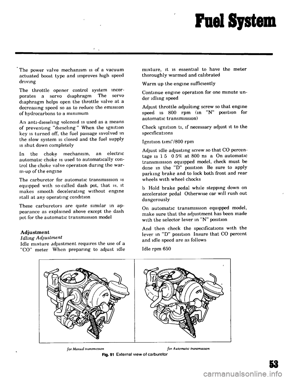
These
carburetors
are
qUIte
SImIlar
In
ap
pearance
as
explaIned
above
except
the
dash
pot
for
the
automatIc
transmISSion
model
Adjustment
Idhng
Adjustment
Idle
mixture
adjustment
requIres
the
use
of
a
CO
meter
When
prepatlng
to
adjust
Idle
mIxture
It
IS
essentIal
to
have
the
meter
thoroughly
warmed
and
cahbrated
Warm
up
the
engIne
suffiCiently
ContInue
engme
operatIOn
for
one
mmute
un
der
ldhng
speed
Adjust
throttle
adjustIng
screw
so
that
engme
speed
IS
800
rpm
m
N
pos1tIon
for
automatic
transmiSSIOn
Check
IgmtlOn
tl
If
necessary
adjust
It
to
the
speCificatIOns
IgnItIOn
tImlo
800
rpm
Adjust
Idle
adJustmg
screw
so
that
CO
percen
tage
IS
1
5
0
50
at
800
ns
a
On
automatIc
transmiSSIOn
eqUipped
model
check
must
be
done
In
the
D
poSItIon
Be
sure
to
apply
parkmg
brake
and
to
lock
both
front
and
rear
wheels
With
wheel
chocks
b
Hold
brake
pedal
while
steppIng
down
on
accelerator
pedal
OtherWise
car
Will
rush
out
dangerously
On
automatIc
transmiSSIOn
eqUIpped
model
make
sure
that
the
adjustment
has
been
made
With
the
selector
lever
In
N
posItIon
And
then
check
the
specificatIOns
With
the
lever
In
D
pOSitIOn
Insure
that
CO
percent
and
Idle
speed
are
as
follows
Idle
rpm
650
for
Manual
transmISSion
for
Automatic
transmISSion
Fig
91
External
view
of
carburetor
3
Page 51 of 136
ruel
Sptem
CO
percentage
with
lever
In
D
posltton
15
050
If
necessary
adjust
by
progressively
turmng
throttle
adjustIng
screw
and
Idle
adJusttng
screw
unttl
correct
adjustments
are
made
Notes
a
Do
not
attempt
to
screw
down
the
Idle
adjusting
screw
completely
to
aVOid
damage
to
the
tip
which
will
tend
to
cause
malfunctions
b
After
idle
adjustment
has
been
made
shift
the
lever
to
UN
or
P
position
for
automatic
transmission
c
Remove
wheel
chocks
before
starting
the
car
Idle
Limiter
Cap
Do
not
remove
this
Idle
hmlter
cap
unless
nccesbary
If
this
Unit
IS
removed
It
IS
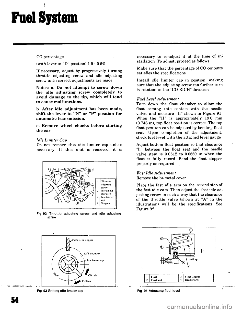
I
Throttle
adJu
tmg
suew
2
Idle
adJu
t
Ing
rcw
3
Idle
hmlter
p
4
Stopper
FIg
92
Throttle
adjusting
screw
and
Idle
adjusting
screw
rl1urdor
topper
Fig
93
Setting
Idle
limiter
cap
54
necessary
to
re
adJust
it
at
the
time
of
In
stallatIOn
To
adjust
proceed
as
follows
Make
sure
that
the
percentage
of
CO
contents
sattsfies
the
speClficattons
Install
idle
hmIter
cap
In
poSItIOn
makIng
sure
that
the
adjustIng
screw
can
further
turn
rotatIOn
In
the
CO
RICH
dIrectIOn
Fuel
Level
Adjustment
Turn
down
the
float
chamber
to
allow
the
float
comIng
Into
contact
WIth
the
needle
valve
and
measure
R
shown
In
Figure
91
When
the
H
IS
approximately
190
mm
0748
In
top
float
posltton
IS
correct
The
top
float
pOSitIOn
can
be
adjusted
by
bendIng
float
seat
Upon
completIOn
of
the
adjustment
check
fuel
level
WIth
the
attached
level
gauge
Adjust
bottom
float
posItion
so
that
clearance
h
between
the
float
seat
and
the
needle
valve
stem
IS
0
0512
to
00669
In
when
the
float
IS
fully
raIsed
Bend
the
float
stopper
properly
as
reqUIred
Fast
Idle
Adjustment
Remove
the
bl
metal
cover
Place
the
fast
Idle
arm
on
the
second
step
of
the
fast
idle
cam
Then
adjust
the
fast
Idle
ad
JustIng
screw
In
such
a
way
that
the
clearance
of
the
throttle
valve
shown
at
A
In
the
Illustratton
Will
be
the
speCificatIOns
See
Figure
92
IH
Float
Float
seat
3
noall
topper
4
Needle
alve
Fig
94
AdJusting
float
level
Page 53 of 136
ruel
Sptem
Clearance
of
throttle
Engme
revolutIon
valve
A
ill
rpm
Manual
transmiSSIOn
o
0315
to
0
0346
I
750
to
2
050
Automatic
transmISSIOn
00421
to
0
0461
2
650
to
2
950
c
Rubbu
bJ
nd
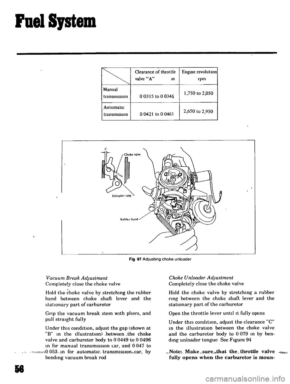
Fig
97
Adjusting
choke
unloader
Vacuum
Break
Adjustment
Completely
close
the
choke
valve
Hold
the
choke
valve
by
stretching
the
rubber
band
between
choke
shaft
lever
and
the
btatlOnary
part
of
carburetor
Grip
the
vacuum
break
stem
with
phers
and
pull
straIght
fully
Under
thIS
condltton
adjust
the
gap
shown
at
8
In
the
111ustratlOnl
between
the
choke
valve
and
carburetor
body
to
00449
to
0
0496
In
for
manual
transmission
tar
and
0047
to
0
053
1n
for
automattc
transrnlsslOn
car
by
bending
vacuum
break
rod
51
Choke
Unloader
Adjustment
Completely
close
the
choke
valve
Hold
the
choke
valve
by
stretching
a
rubber
ring
between
the
choke
shaft
lever
and
the
stattonary
part
of
the
carburetor
Open
the
throttle
lever
unttllt
fully
opens
Under
thiS
condltton
adjust
the
clearance
C
In
the
IllustratIOn
between
the
choke
valve
and
the
carburetor
body
to
0
079
In
by
ben
ding
unloader
tongue
See
Figure
94
Note
Make
sure
that
the
throttle
valve
fully
opens
when
the
carburetor
is
moun
Page 98 of 136
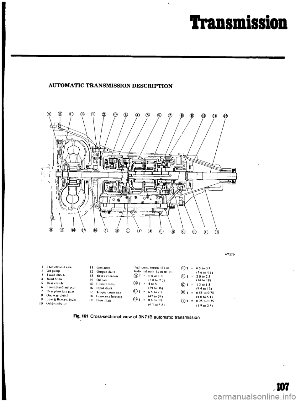
Transmission
AUTOMATIC
TRANSMISSION
DESCRIPTION
I
Ii
9
0
@
@
AT270
1
U
lllll
II
O
l
rn
lr
II
hkl1lllj
ItlrllUl
I
II
01
15
tu
07
011
pump
12
OUllJllt
holtl
h
llt
Ih
kl
Illllt
Ihl
16
to
i
II
1
1
runl
dUlth
13
Kl
JT
llhlOIl
01
10
01
20
to
2
5
4
B
H1d
brJkl
14
011
p
Jll
l
i
H
hl
7
14toHn
5
Re
u
du
h
15
lIT01
tlvt
@
41u5
@I
I
310
I
8
6
I
ronl
plJllctJry
lJr
16
Input
11
111
0
29101fll
194
013
1
Rldr
pIJIJC
IJ
ry
j
l
Lr
11
1
m
lu
n
lIh
T
6
5
tn
15
@
055toO
5
OIll
JYdutdt
rllT
11
l1
11l
@I
147
to
541
40
0
5
4
9
I
lW
RlVlr
l
bl
Jkl
19
Dm
l
plJh
16
III
8
CDT
l
2S
to
U
l
S
10
011
dl
nbulm
4
11n
i
HI
I
I
to
2
iJ
Flg
161
Cross
sectIonal
view
of
3N71B
automatic
transmIssIon
107