1969 DATSUN B110 ignition
[x] Cancel search: ignitionPage 2 of 136
lI
I
DATSUN
1200
RANGE
1971
1973
MAINTENANCE
REPAIR
BY
DRAKE
AUTOMOTIVE
EDITORS
Quick
Referencelodel
MAINTENANCE
TUNE
UP
5
STEERING
89
ENGINEERING
13
REAR
DRIVE
ELECTRICAL
SYSTEM
35
SUSPENSION
93
IGNITION
SYSTEM
43
CLUTCH
99
FUEL
SYSTEM
49
TRANSMISSION
103
COOLING
SYSTEM
63
BODY
WORK
111
BRAKES
67
SPECIFICATIONS
129
FRONT
SUSPENSION
83
The
purpose
of
this
manual
IS
to
provide
the
automobile
owner
and
mechanic
with
a
reference
source
with
which
he
can
perform
normal
service
operations
We
endeavor
to
lOcorporate
the
latest
manufacturing
design
changes
and
up
to
date
specifications
at
the
time
of
publication
While
every
effort
IS
made
to
attain
accuracy
the
Publisher
cannot
be
held
responsible
for
manufacturing
changes
typographical
errors
or
omiSSions
Upon
compIling
the
information
contained
herein
we
have
tried
to
be
brief
and
Simple
relvlng
on
the
combination
of
photographs
Illustrations
and
text
to
make
thIS
manual
a
useful
tool
DRAKE
PUBLISHERS
INC
361
PARK
AVENUE
SOUTH
NEW
YORK
NY
10016
Page 4 of 136

able
of
Contents
MAINTENANCE
TUNE
UP
DIsassembly
32
InspectIOn
RepaIr
33
VALVE
CLEARANCES
6
AdJustmg
Regulator
33
ENGINE
OIL
6
Assembly
33
OIL
FILTER
7
COOLANT
7
COMPRESSION
7
ELECTRICAL
SYSTEM
BATTERY
8
IGNITION
TIMING
8
STARTER
36
DIstributor
Breaker
Pomt
9
Removal
37
Condenser
9
InstallatIOn
37
Spark
Plugs
9
Trouble
Shootmg
37
Carburetor
9
ALTERNATOR
36
Idle
LImIter
Cap
10
Removal
37
Dash
Pot
automatic
transmISSIOn
11
InstallatIOn
37
model
only
11
REGULATOR
39
Carburetor
Return
Sprmg
11
DeSCriptIOn
39
Fuel
Filter
11
Trouble
Shootmg
40
ENGINE
IGNITION
SYSTEM
DESCRIPTION
14
DISTRIBUTOR
44
REMOVAL
14
ConstructIOn
44
INSTALLATION
14
Checkmg
and
Adjustment
44
CLEANING
INSPECTION
14
SP
ARK
PLUGS
46
DISASSEMBL
Y
14
DeSCriptIOn
46
INSPECTION
REPAIR
18
InspectIOn
46
PreparatIOn
18
Cleamng
Regap
47
Cyltnder
Head
18
Valve
Assembly
18
Valve
Spnng
19
Valve
Rocker
Shaft
Rocker
Arm
19
FUEL
SYSTEM
Valve
LIfter
Push
Rod
20
Camshaft
Camshaft
Bearmg
20
FUEL
FILTER
50
Valve
Tlmmg
20
DESCRIPTION
50
Cyltnder
Block
21
REMOVAL
50
PIston
Piston
Pm
Plsto
LRmg
21
INSTALLATION
50
Connectmg
Rod
23
FUEL
PUMP
50
Crankshaft
24
DeSCriptIOn
50
Bushmg
Bearing
24
Testmg
51
Crankshaft
Sprocket
Removal
DIsassembly
52
Camshaft
Sprocket
25
InspectIOn
52
Flywheel
25
Assembly
52
ASSEMBL
Y
25
CARBURETOR
52
PrecautIOn
25
DeSCription
52
Cyltnder
Head
25
Adjustment
53
PIston
ConnectIng
Rod
26
Removal
58
Engme
26
DIsassembly
58
OIL
PUMP
32
Cleanmg
InspectIOn
59
Removal
Engme
m
vehicle
32
Assembly
InstallatIOn
60
I
Page 6 of 136

fable
of
Contents
BODY
WORK
SPECIFICATIONS
I
HOOD
112
SERVICE
DATA
130
Removal
112
ENGINE
134
InstallatIOn
112
General
SpeCificatIOn
134
HOOD
LOCK
112
Tlghtemng
Torque
134
Removal
112
SpeCIficatIOn
135
Adjustment
112
Coohng
System
139
LubncatlOn
114
Fuel
System
140
TRUNK
LID
LOCK
116
Starter
142
Removal
116
Alternator
143
Adjustment
116
Regulator
144
TRUNK
LID
TORSION
BAR
116
Dlstnbutor
145
DOOR
CONSTRUCTION
117
IgnItIOn
Cot
145
WIRING
DIAGRAMS
118
CLUTCH
146
BULB
SPECIFICATIONS
120
NOTES
174
HEADLAMP
121
THERMOMETER
AND
FUEL
METER
122
OIL
PRESSURE
AND
IGNITION
WARNING
LAMPS
126
I
I
t
I
3
Page 10 of 136
aiDtenaDce
TUDe
up
ting
tightly
m
spark
plug
hole
of
a
cylin
der
The
tester
is
used
to
determme
whether
cylinder
can
hold
compression
or
whether
there
IS
excessive
leakage
past
rings
etc
Test
compressIOn
wIth
engme
warm
all
spark
plugs
removed
and
throttle
and
choke
valve
opened
No
cyhnder
compressIOn
should
be
less
than
80
of
highest
cyhnder
s
Excessive
variatIOn
between
cyhnders
accompamed
by
low
speed
missing
of
the
cyllndel
usually
10
dlcates
a
valve
not
properly
seating
or
a
blOken
pIston
ring
Low
preSsures
even
though
umform
may
indIcate
worn
rings
ThIs
may
be
accompamed
by
excessive
011
consumptIOn
Test
Conclusion
If
one
or
more
cyhnders
read
low
Inject
about
one
tablespoon
of
engine
011
on
top
of
the
plstons
In
low
readmg
cyhnders
through
spark
plug
hole
Repeat
compressIOn
check
on
these
cy
II
nders
If
compressIOn
Improves
conSiderably
piston
rings
are
defectIve
If
compressIOn
does
not
Improve
valves
are
stIcking
or
seatIng
Improperly
If
two
adjacent
cyhnders
mdlcate
low
com
pressIOn
and
mjectmg
011
on
pistons
does
not
Increase
compreSSIOn
the
cause
may
be
a
cylInder
head
gasket
leak
between
the
cyhn
ders
Engine
011
and
coolant
In
cylInder
could
result
from
this
problem
CompressIOn
pressure
178
to
206
pSI
at
350
rpm
BATIERY
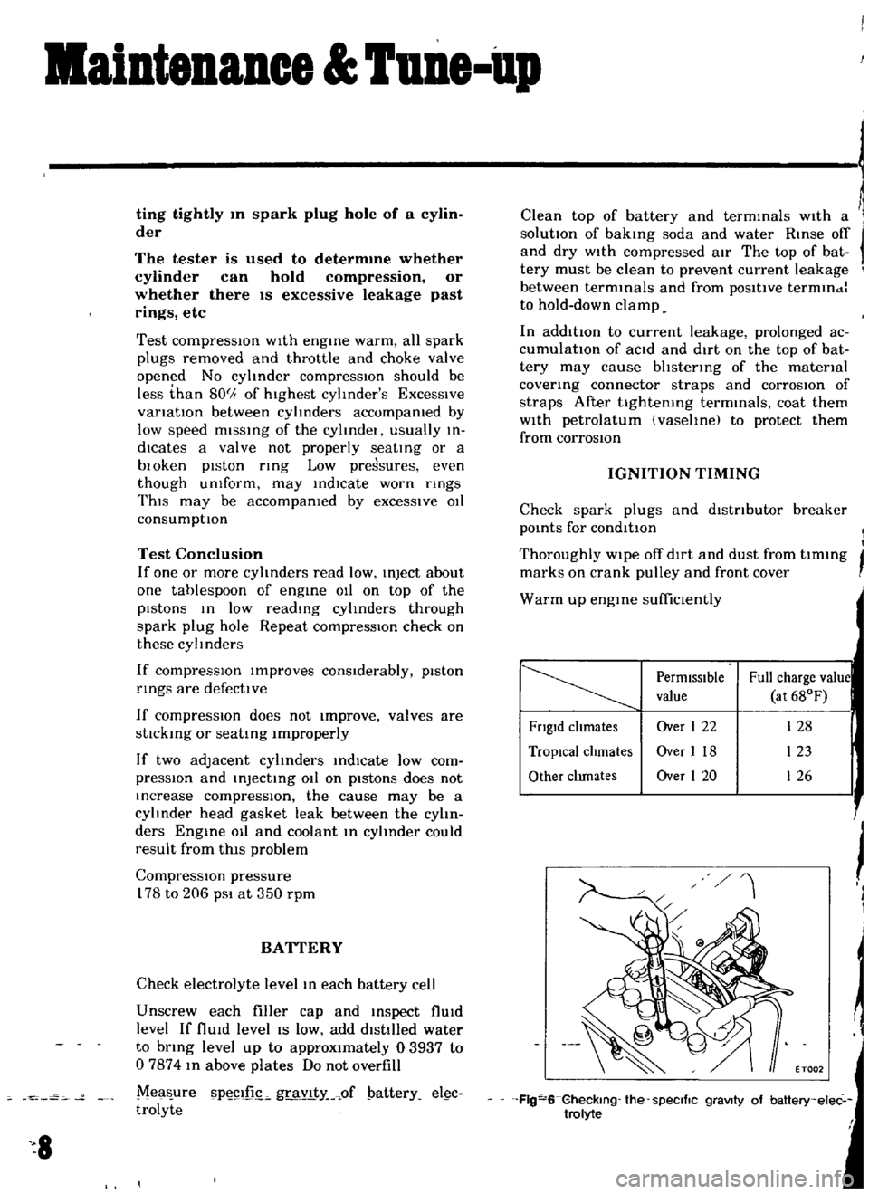
Check
electrolyte
level
10
each
battery
cell
Unscrew
each
filler
cap
and
Inspect
flUId
level
If
flUId
level
IS
low
add
dIstilled
water
to
bring
level
up
to
approximately
03937
to
07874
In
above
plates
Do
not
overfill
Mea
ure
P
illL
gravlty
of
pattery
el
c
trolyte
8
Clean
top
of
battery
and
terminals
With
a
solutIOn
of
baking
soda
and
water
Rinse
off
and
dry
WIth
compressed
atr
The
top
of
bat
tery
must
be
clean
to
prevent
current
leakage
between
terminals
and
from
poSItive
termlndl
to
hold
down
clamp
In
additIOn
to
current
leakage
prolonged
ac
cumulatIon
of
aCId
and
dirt
on
the
top
of
bat
tery
may
cause
bhstenng
of
the
material
covering
connector
straps
and
corrOSIOn
of
straps
After
tightening
terminals
coat
them
With
petrolatum
vasehnel
to
protect
them
from
corrosIOn
IGNITION
TIMING
Check
spark
plugs
and
dIstributor
breaker
pOints
for
conditIon
I
I
Thoroughly
wipe
off
dIrt
and
dust
from
tlmmg
j
marks
on
crank
pulley
and
front
cover
Warm
up
engine
suffiClently
PermIssIble
Full
charge
value
value
at
68OF
Fngld
chmates
Over
1
22
128
TropIcal
chmates
Over
I
18
123
Other
clunates
Over
1
20
126
j
J
I
ET002
Flg
S
Gheckmg
the
speCific
gravity
of
baltery
elec
trolyte
f
Page 11 of 136
l
aiDteDaDce
UDe
up
Install
a
timing
lIght
on
No
1
cyhnder
spark
plug
WIre
and
Install
a
tachometer
Set
Idhng
ipeed
to
approximately
800
rpm
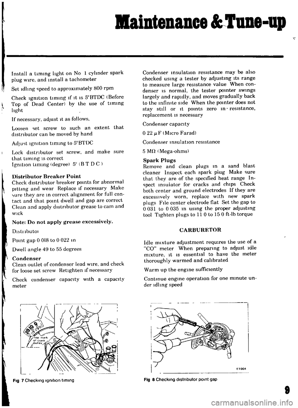
Check
19mtlOn
tImmg
If
It
IS
50BTDC
Before
Top
of
Dead
Center
by
the
use
of
tlmmg
hght
If
necessary
adjust
It
as
follows
Loosen
iet
screw
to
such
an
extent
that
dlstnbutor
can
be
moved
by
hand
AdJu
it
IgmtlOn
tIming
to
50BTDC
Lock
dlstnbutor
set
screw
and
make
sure
that
tlmmg
IS
correct
IgnitIOn
tImmg
degreel
50
B
T
DC
Distributor
Breaker
Point
Check
dlstnbutor
breaker
pomts
for
abnormal
pItting
and
wear
Replace
If
necessary
Make
wre
they
are
In
correct
ahgnment
for
full
con
tact
and
that
pOint
dwell
and
gap
are
correct
Clean
and
apply
dlstnbutor
grease
to
cam
and
WIck
Note
Do
not
apply
grease
excessively
Dl
tI
IbutOl
POint
gap
0
018
to
0
022
In
Dwell
angle
49
to
55
degrees
Condenser
Clean
outlet
of
condenser
lead
WIre
and
check
for
loose
set
screw
RetIghten
If
necessary
Check
condenber
capacIty
With
a
capacity
meter
Fig
7
Checking
Igmllon
timing
Condenser
msulatlOn
resistance
may
be
also
checked
usmg
a
tester
by
adjusting
ItS
range
to
measure
large
resIstance
value
When
con
denser
IS
normal
the
tester
pomter
swmgs
largely
and
rapidly
and
moves
gradually
back
to
the
Infimte
SIde
When
the
pomter
does
not
stay
still
or
It
pomts
zero
m
reSIstance
replacement
IS
necessary
Condenser
capacIty
022
J
F
MIcro
Farad
Condenser
InsulatIOn
resIstance
5
Mn
Mega
ohms
Spark
Plugs
Remove
and
clean
plugs
In
a
sand
blast
cleaner
Inspect
each
spark
plug
Make
iure
that
they
are
of
the
specified
heat
range
In
ipect
msulator
for
cracks
and
chIps
Check
both
center
and
ground
electrodes
If
they
are
excessIVely
worn
replace
WIth
new
spark
plugs
File
center
electrode
flat
Set
the
gap
to
0031
to
0035
m
USIng
the
proper
adjustIng
tool
Tighten
plugs
to
11
0
to
150
ft
Ib
torque
CARBURETOR
Idle
mixture
adjustment
requIres
the
use
of
a
CO
meter
When
preparIng
to
adjust
Idle
mixture
It
IS
essential
to
have
the
meter
thoroughly
warmed
and
cahbrated
Warm
up
the
engme
suffiCiently
ContInue
engIne
operatIOn
for
one
mmute
un
der
ldhng
speed
I
i
I
I
I
I
I
I
ETOQ4
Fig
8
Checking
dlstnbutor
POint
gap
Page 12 of 136
aiDteDaDce
UDe
up
Adjust
throttle
adjusting
screw
so
that
engme
speed
1S
800
rpm
m
N
positIOn
for
automatic
transmIssIOn
Check
IgnitIOn
tlmmg
If
necessary
adjust
1t
to
the
specIficatIOns
IgnitIOn
timing
50
800
rpm
Adjust
Idle
adjusting
screw
so
that
CO
percen
tage
IS
1
5
t0
5
ff
Repeat
the
adjustments
as
desctlbed
In
steps
3
above
so
that
CO
percentage
IS
15
t0
5
ff
at
800
rpm
Cautions
a
On
automatic
transmission
equipped
model
check
must
be
done
in
the
D
position
Be
sure
to
apply
parking
brake
and
to
lock
both
front
and
rear
wheels
wIth
wheel
chocks
b
Hold
brake
pedal
while
stepping
down
on
accelerator
pedal
Otherwise
car
will
rush
out
dangerously
On
automatic
transmISSIOn
eqUIpped
model
make
sure
that
the
adjustment
has
been
made
wIth
the
selector
lever
In
N
posItion
And
then
check
the
specificatIOns
with
the
lever
In
D
posItion
Insure
that
CO
percent
and
Idle
speed
are
as
follows
Idle
rpm
650
Idle
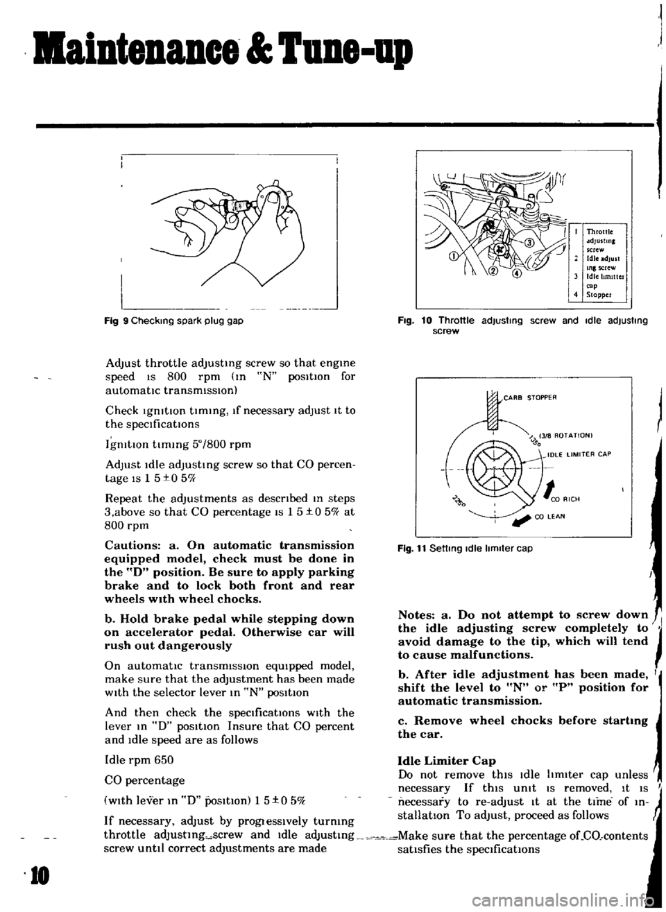
Limiter
Cap
CO
percentage
Do
not
remove
this
Idle
hm1ter
cap
unless
necessary
If
this
Unit
IS
removed
It
IS
I
with
lever
In
D
PoSitIOn
1
5
t
0
5
k
necessary
to
re
adJust
It
at
the
time
of
In
If
necessary
adjust
by
progIesslvely
turmng
stallatlon
To
adjust
proceed
as
follows
throttle
adJustlng
screw
and
Idle
adJustmg
Make
sure
that
the
percentage
oLCO
contents
screw
until
correct
adjustments
are
made
satisfies
the
specifications
I
I
I
I
J
Fig
9
Checking
spark
plug
gap
10
Throttle
sdJustlnl
screw
Idle
adjust
Inlscrew
Idle
Itmlttc
r
cap
4
Stopper
Fig
10
Throttle
adjusting
screw
and
Idle
adjusting
screw
CARB
STOPPER
Fig
11
Setting
Idle
limiter
cap
Notes
a
Do
not
attempt
to
screw
down
the
idle
adjusting
screw
completely
to
JI
avoid
damage
to
the
tip
which
will
tend
to
cause
malfunctions
b
After
idle
adjustment
has
been
made
I
shift
the
level
to
N
or
P
position
for
automatic
transmission
c
Remove
wheel
chocks
before
startmg
the
car
Page 36 of 136
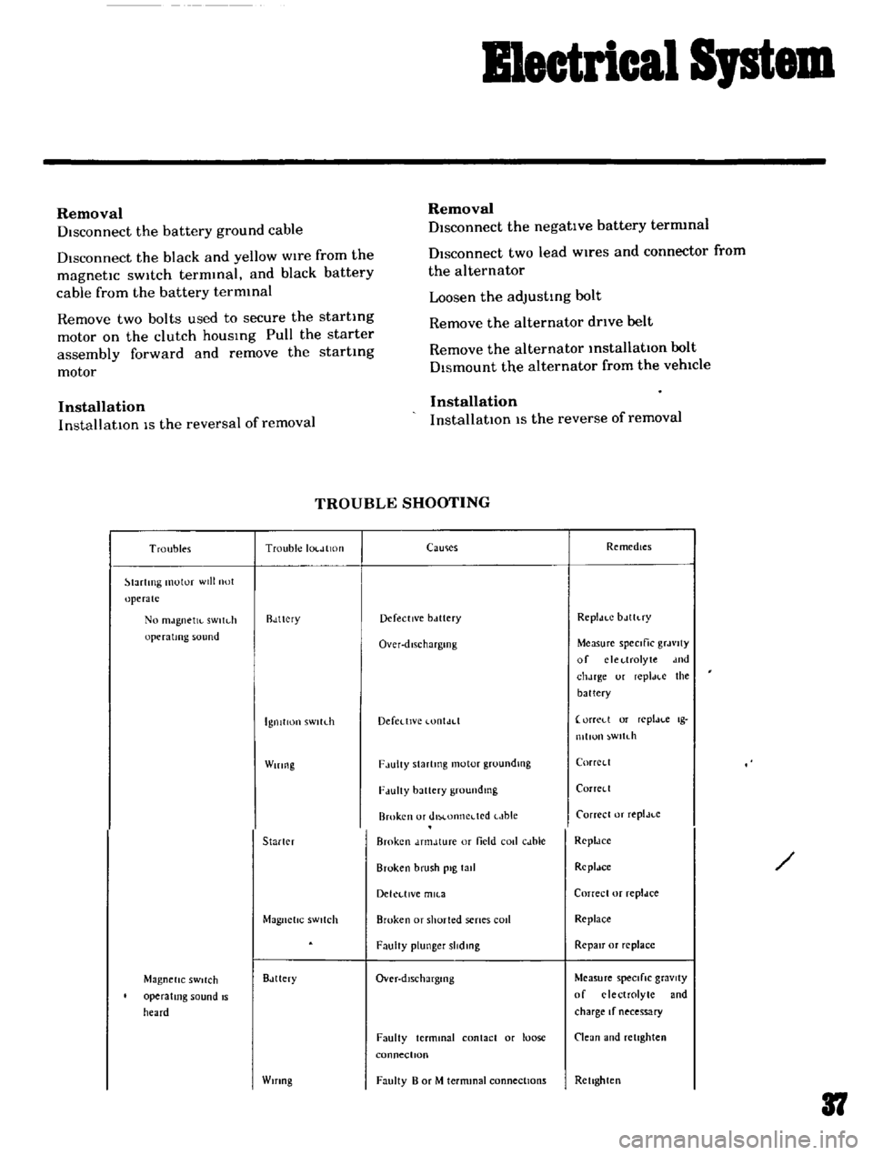
B1eetrical
Iptem
Removal
DIsconnect
the
battery
ground
cable
Disconnect
the
black
and
yellow
wIre
from
the
magnetic
sWitch
termmal
and
black
battery
cable
from
the
battery
termmal
Remove
two
bolts
used
to
secure
the
startmg
motor
on
the
clutch
housing
Pull
the
starter
assembly
forward
and
remove
the
starting
motor
Installation
InstallatlOn
IS
the
reversal
of
removal
Removal
Disconnect
the
negatIve
battery
termmal
DIsconnect
two
lead
wires
and
connector
from
the
alternator
Loosen
the
adjusting
bolt
Remove
the
alternator
drIve
belt
Remove
the
alternator
installation
bolt
Dismount
the
alternator
from
the
vehIcle
Installation
InstallatlOn
1S
the
reverse
of
removal
TROUBLE
SHOOTING
Troubles
Trouble
IOl
JlltHI
lartlTlg
motor
will
not
operate
No
mJgnetJl
sWltdl
operating
sound
Rdttcry
IgnitIon
sWltLh
Wiring
Starler
Magnetic
SWitch
Magnetic
SWitch
operating
sound
IS
heard
Bdttery
Wifing
CaUlies
Remedies
Defective
bclttery
Rcpldt
C
bJlh
ry
Over
dlschargmg
Measure
speCific
grJvlty
of
clcl
lrolyte
dnd
chJrge
ur
repl
H
e
the
battery
Defedlvc
lontJd
orreLl
or
replJl
c
Ig
mllun
wltdl
F
lulty
Slartmg
motor
groundlllg
CorrCl
l
F
lUlty
battery
groundmg
Corrcll
Broken
or
dlM
onncdcd
t
Jble
Carrece
or
replJt
c
Broken
dnnJture
or
field
coli
cJble
RcpldCC
Broken
brush
pig
tall
Rcpldce
Dekl
llVe
mll
3
Correcl
or
repldce
Broken
or
shorted
senes
cod
Replace
FaulIy
plunger
slidmg
RepaIr
or
replace
Over
dlschargmg
Measure
speCifiC
gravity
of
electrolyte
and
charge
If
necessary
Faulty
terminal
contact
or
loose
connectIOn
Clean
and
retighten
Faulty
B
or
M
termmal
connections
Rellghten
37
Page 37 of 136
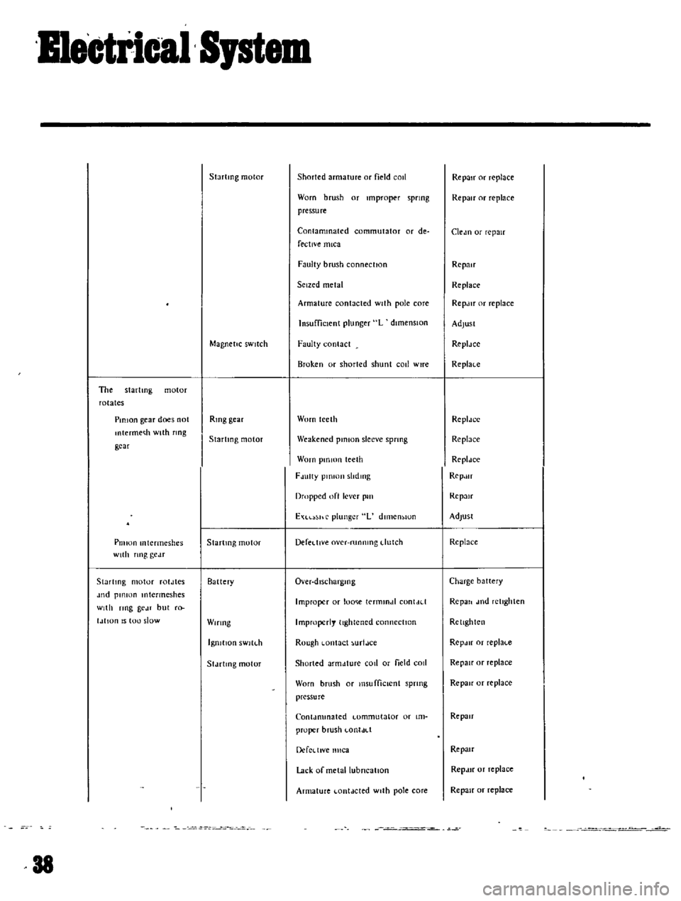
Bmetrlcal
Spt
The
startmg
motor
rotates
PinIOn
gear
does
not
mtermec
h
with
flOg
gear
Pillion
mtermeshes
with
nng
gc
lT
Startmg
motor
roldles
Jud
pillion
Intermeshes
With
ring
gc
n
but
r
l
IlIan
IS
tou
slow
Startmg
motor
Magnetic
SWitch
Rmg
gear
Startmg
motor
Startmg
motor
Battery
Wiring
IgnitIOn
sWltl
h
Sldelmg
motor
38
Shorted
armature
or
field
cOIl
Worn
brush
or
Improper
spring
pressure
Contaminated
commutator
or
de
fective
mica
Faulty
brush
connection
Seized
metal
Armature
contacted
With
pole
core
Insufficient
plunger
L
dimenSIOn
Faulty
contact
Brok
en
or
shorted
shunt
call
wire
Worn
teeth
Weakened
pinion
sleeve
sprmg
Worn
pm
IOn
teeth
FJulty
plOlOJl
slldmg
Dropped
oft
lever
pill
EXl
hr
plunger
L
dlll1en
IOn
Defel
tlve
over
runnmg
dutch
Over
dlscharglOg
Improper
or
lome
termmdl
con
Lid
Improperly
tightened
connection
Rough
Lontact
urtJce
Shorted
armdture
COil
or
field
cOIl
Worn
brush
or
I11sufficlCnt
spnng
pressure
Conldmmated
Lomrnutator
or
Im
proper
brush
LonldLl
DercLllVe
nllca
Lack
or
metallubneallon
Armature
Lontdcted
With
pole
core
Repair
or
replace
Repair
or
replace
Cledn
or
repair
Repair
Replace
RepJlr
or
replace
AdjUst
ReplJee
Replace
ReplJee
Replnee
Rcpldce
RepJlr
Rep
m
Adjust
Re
place
Charge
battery
Repall
l11d
retIghten
Rellghten
RepJIr
or
replaLc
Repair
or
replace
Repair
or
replace
Repair
Repau
Repdlf
or
replace
Repair
or
replace