1969 DATSUN B110 ignition
[x] Cancel search: ignitionPage 38 of 136
llectrical
Spt
When
Harting
lWltch
I
IgllltlUn
iwltch
FJuhy
rctuflung
Repldce
set
10
OFf
the
slJrl
motor
do
nut
MJgnclK
Wltdl
Seiad
contJr
l
Repldcc
IIlg
I
op
Shorted
1
011
Replace
Faulty
plunger
slidmg
Replace
StJflillg
motOr
Pillion
does
not
dlsengJge
from
the
Repair
or
replace
nng
gedr
smoothly
Pinion
sphne
dot
110t
disengage
Repan
or
replJce
moothly
SCl7Cd
pinIOn
metal
Replace
REGULATOR
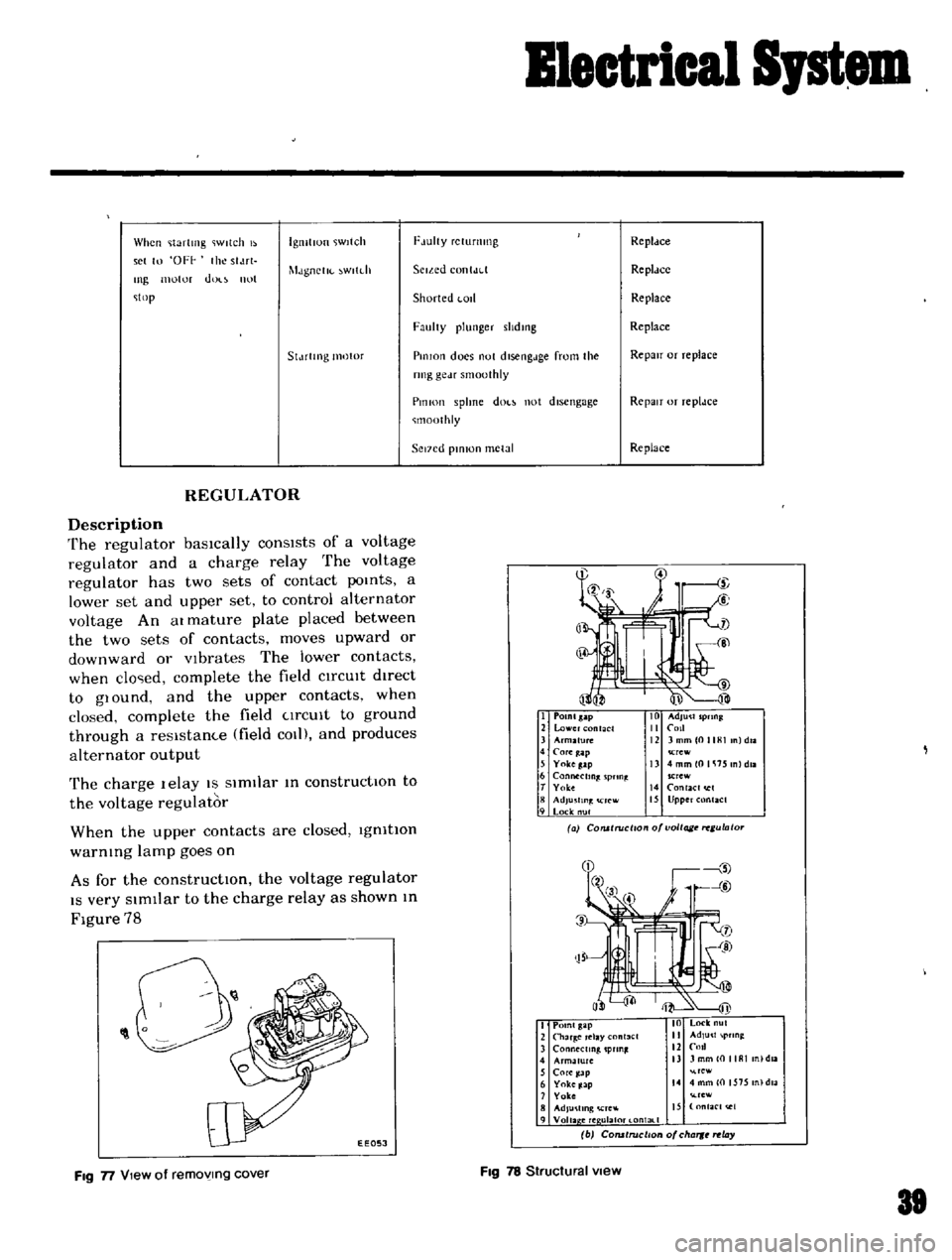
Description
The
regulator
basically
consists
of
a
voltage
regulator
and
a
charge
relay
The
voltage
regulator
has
two
sets
of
contact
poInts
a
lower
set
and
upper
set
to
control
alternator
voltage
An
at
mature
plate
placed
between
the
two
sets
of
contacts
moves
upward
or
downward
or
Vibrates
The
lower
contacts
when
clo
ed
complete
the
field
CIrCUIt
dIrect
to
glOund
and
the
upper
contacts
when
closed
complete
the
field
CIrCUIt
to
ground
through
a
resIstam
e
field
COl
and
produces
alternator
output
The
charge
lelay
IS
SimIlar
In
constructIOn
to
the
voltage
regulator
When
the
upper
contacts
are
closed
IgnitIOn
warnIng
lamp
goes
on
As
for
the
constructIOn
the
voltage
regulator
IS
very
SImIlar
to
the
charge
relay
as
shown
In
Figure
78
I
POlnlsap
2
lower
nt
CI
3
Arm2fu1C
4
COfe
ap
5
Yokeg
lp
6
Connecting
pnn
t
T
Yolce
8
AdJu
fln
rcw
9
Lock
nul
Crew
13
4mmlOlli15
nldll
SCrew
14
RlaCI
I
15
Upper
Rlact
a
COlUlruci
o
o
voltage
ulato
O
0
1
EEOSJ
I
Point
gap
2
Char
Clay
nl3el
3
ConMctmg
pun
4
Armature
nl
daa
5
Core
ap
re
6
Yoke
Jap
14
4
mm
0
1575
n
dla
7
Yoke
rew
8
AdJu
llng
Cre
IS
nfaC
t
e1
9
Voila
ere
ulal0t
l
ontal
1
b
COfUtruclton
of
cha
rt
ay
FIg
n
View
of
removing
cover
FIg
78
Structural
view
81
Page 42 of 136
lenition
Sptem
IGNITION
SECONDARY
COI
L
COI
L
CAP
BREAKER
POTNT
cr
r
7
W
tc
l
uToRI
8
TO
STARTER
l
J
ROTOR
HEAD
SPARK
PLUG
Fig
19
Igmtlon
system
Circuit
diagram
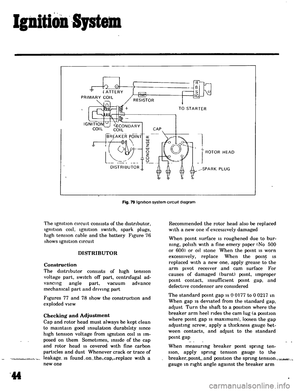
The
IgmtlOn
CirCUIt
conSIsts
of
the
distributor
IgmtIon
cOli
IgmtIon
sWitch
spark
plugs
hIgh
tensIOn
cable
and
the
battery
Figure
76
shows
IgmtlOn
CirCUIt
DISTRIBUTOR
Construction
The
dIstributor
consists
of
high
tension
voltage
part
SWitch
off
part
centrifugal
ad
vancing
angle
part
vacuum
advance
mechamcal
part
and
drlvmg
part
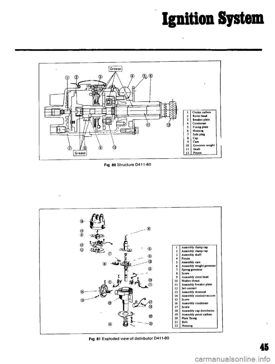
Figures
77
and
78
show
the
constructIOn
and
exploded
view
Checking
and
Adjustment
Cap
and
rotor
head
must
always
be
kept
clean
to
maintain
good
insulation
durability
since
high
tensIOn
voltage
from
IgmtIon
cOil
IS
Im
posed
on
them
SometImes
inside
of
the
cap
and
rotor
head
IS
covered
wIth
fine
carbon
partIcles
and
dust
Whenever
crack
or
trace
of
leakage
IS
found
on
the
cap
replace
w1th
a
new
one
44
Recommended
the
rotor
head
also
be
replaced
wIth
a
new
one
If
excessively
damaged
When
pomt
surface
IS
roughened
due
to
bur
nlng
polish
with
a
fine
emery
paper
No
500
or
600
or
011
stone
When
the
point
IS
worn
excessively
replace
When
the
POIn
IS
replaced
with
a
new
one
apply
grease
to
the
arm
pivot
receiver
and
cam
surface
For
causes
of
damaged
burnt
point
Improper
pomt
contact
msufficlent
point
gap
and
defective
condenser
are
conSidered
The
standard
pomt
gap
IS
0
0177
to
0
0217
m
When
gap
IS
devIated
from
the
standard
gap
adjust
Turn
the
shaft
to
a
posItIon
where
the
breaker
arm
heel
rides
the
cam
lug
a
posItIon
where
pomt
gap
IS
maxImum
loosen
the
gap
adjusting
screw
apply
a
thIckness
gauge
bet
ween
contacts
and
adjust
to
the
standard
pomt
gap
When
measurmg
breaker
pomt
spring
ten
SIOn
apply
sprmg
tensIOn
gauge
to
the
breaker
pomt
and
posItIon
the
sprmg
tenslOn
gauge
m
right
angle
agamst
the
breaker
arm
Page 43 of 136
Ignition
Iptem
FIg
80
Structure
D411
80
CID
0
A
t
CID
l@J
rf
@
@
@
2
@
@
ID
@
FIg
81
Exploded
View
of
dlstnbutor
D411
80
1
Center
carbon
2
Rotor
head
3
Breaker
plate
4
Condenser
5
FIxing
plate
6
Housing
1
Side
plug
8
Cap
9
Com
10
Governor
werght
11
Sh
lft
l2
PIRIOn
1
Assembly
clamp
cap
2
Aucmbly
clamp
cap
3
Assembly
shaft
4
PlOlon
5
A
uembly
eam
6
Assembly
weight
governor
7
Spnng
governor
8
Screw
9
Assembly
rotor
head
10
Washer
thrust
II
Assembly
breaker
plate
12
Set
contact
13
Assembly
termmaJ
14
Assembly
control
vacuum
IS
Screw
16
AssembJy
condenser
17
Screw
J
8
Assembly
cap
dJstnbutor
19
Assembly
pomt
carbon
20
Plate
fixing
21
Bolt
22
Housing
45
Page 44 of 136
Ignition
Sptem
The
standard
breaker
pOint
spring
tensIOn
IS
1
1
to
1
4
lb
Replace
If
devIated
Performance
of
condenser
IS
affected
by
Im
proper
setting
contaminatIOn
and
reductIOn
of
In
ulatlOn
resIstance
Thus
pellOdlcal
checking
I
I
eqlJ
lred
to
maintain
the
outlet
of
lead
wire
clean
and
to
prevent
et
screw
from
loosening
Checking
the
condenser
capacIty
IS
checked
USing
a
capacity
meter
It
may
be
also
checked
condenser
Isolate
resl
tance
USing
a
tester
by
adjusting
ItS
I
ange
to
measure
large
I
eSlstance
value
When
the
condenser
IS
normal
the
tester
pOinter
SWings
1m
gely
and
rapIdly
and
moves
gradually
back
to
the
Infimte
SIde
When
the
pOinter
does
not
stay
stili
or
It
points
Zero
In
reSIstance
replacement
IS
necessary
Fig
82
AdJusllng
POint
gap
Fig
83
Measunng
breaker
POint
spnng
tension
g
SPARK
PLUGS
Description
The
spark
plugs
are
of
the
re
lster
type
haVing
0
551
In
threads
and
0031
to
0035
11i
gap
Note
All
spark
plugs
installed
on
an
engme
must
be
of
the
same
brand
and
number
of
heat
range
Inspection
Remove
spark
plug
wIre
by
pulhng
on
boot
not
on
WIre
Itself
Remove
spark
plugs
Check
electrodes
and
Inner
and
outer
por
celams
of
plugs
noting
the
type
of
depOSits
and
the
degree
of
electrode
erO
lOn
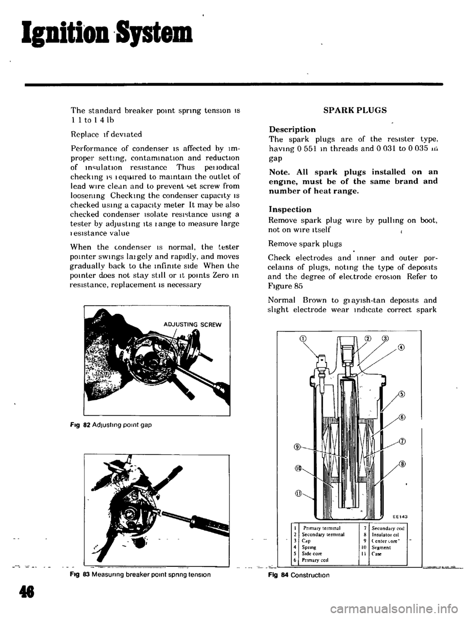
Refer
to
Figure
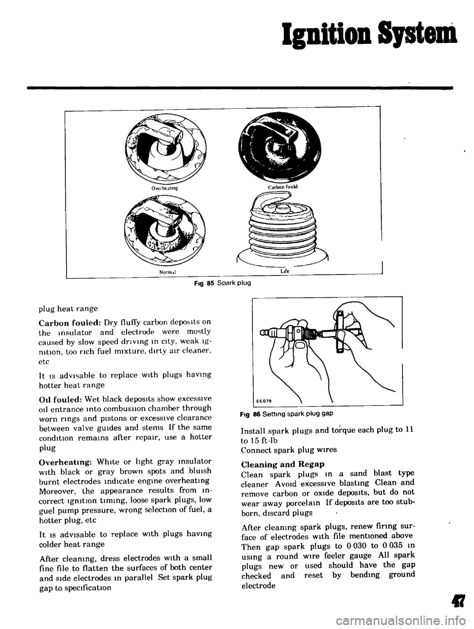
85
Normal
Brown
to
gl
aYlsh
tan
depoSits
and
shght
electrode
wear
indIcate
correct
spark
@
I
Pnmary
terminal
2
Secondary
terminal
3
Cdp
4
Sprang
5
SIde
core
6
Prrmary
coil
7
Secondary
COIl
8
Insulator
011
9
enter
lore
10
Segment
II
Case
Fig
84
Construction
Page 45 of 136
Icnition
Sptem
Ovcrhc
Jtmg
Norm
Jl
i
r
rJ
I
ttr
I
i
V
Carbon
fould
Fig
85
Spark
plug
Life
plug
heat
range
Carbon
fouled
Dry
fluffy
carbon
depo
lts
on
the
Insulator
and
electrode
were
mostly
caused
by
slow
speed
dnvlng
In
cIty
weak
Ig
nltlOn
too
nch
fuel
mixture
dirty
aIr
cleaner
etc
It
IS
advIsable
to
replace
WIth
plugs
havmg
hotter
heat
range
011
fouled
Wet
black
depoSits
show
excesSive
oIl
entrance
Into
combusllon
chamber
through
worn
rmgs
and
pIstons
or
excessIve
clearance
between
valve
gUIdes
and
stems
If
the
same
condition
remams
after
repair
use
a
hotter
plug
Overheatmg
WhIte
or
hght
gray
msulator
WIth
black
or
gray
brown
spots
and
blUIsh
burnt
electrodes
indIcate
engme
overheatIng
Moreover
th
e
appearance
results
from
in
correct
IgnitIon
tIming
loose
spark
plugs
low
guel
pump
pressure
wrong
selectIOn
of
fuel
a
hotter
plug
etc
It
IS
adVisable
to
replace
WIth
plugs
havmg
colder
heat
range
After
cleaning
dress
electrodes
With
a
small
fine
file
to
flatten
the
surfaces
of
both
center
and
Side
electrodes
In
parallel
Set
spark
plug
gap
to
specification
FIg
86
Settmg
spark
plug
gap
Install
spark
plugs
and
torque
each
plug
to
11
to
15
ft
Ib
Connect
spark
plug
wires
Cleaning
and
Regap
Clean
spark
plugs
In
a
sand
blast
type
cleaner
A
VOId
excessIve
blasting
Clean
and
remove
carbon
or
OXide
depoSits
but
do
not
wear
away
porcelain
If
depos1ts
are
too
stub
born
discard
plugs
After
cleaning
spark
plugs
renew
firing
sur
face
of
electrodes
With
file
mentioned
above
Then
gap
spark
plugs
to
0
030
to
0
035
In
uSing
a
round
wire
feeler
gauge
All
spark
plugs
new
or
used
should
have
the
gap
checked
and
reset
by
bending
ground
electrode
II
Page 50 of 136
Fuel
Sptem
The
power
valve
mechanIsm
IS
of
a
vacuum
actuated
boost
type
and
Improves
hIgh
speed
drivIng
The
throttle
opener
control
system
Incor
porates
a
servo
diaphragm
The
servo
dIaphragm
helps
open
the
throttle
valve
at
a
decreasIng
speed
so
as
to
reduce
the
emISSIOn
of
hydrocarbons
to
a
minImum
An
antI
dlesehng
olen01d
IS
used
as
a
means
of
preventIng
dlesehng
When
the
IgnItIOn
key
IS
turned
ofT
the
fuel
passage
Involved
In
the
slow
system
IS
closed
and
the
fuel
supply
IS
shut
down
completely
In
the
chok
mechanIsm
an
electric
automatIc
choke
IS
used
to
automatically
con
trol
the
choke
valve
operatIOn
durIng
the
war
m
up
of
the
engIne
The
carburetor
for
automatic
transmiSSIOn
IS
eqUIpped
WIth
so
called
dash
pot
that
IS
It
makes
smooth
deceleratIng
WIthout
engIne
stall
at
any
operatIng
conditIOn
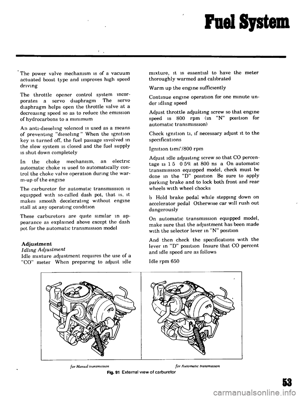
These
carburetors
are
qUIte
SImIlar
In
ap
pearance
as
explaIned
above
except
the
dash
pot
for
the
automatIc
transmISSion
model
Adjustment
Idhng
Adjustment
Idle
mixture
adjustment
requIres
the
use
of
a
CO
meter
When
prepatlng
to
adjust
Idle
mIxture
It
IS
essentIal
to
have
the
meter
thoroughly
warmed
and
cahbrated
Warm
up
the
engIne
suffiCiently
ContInue
engme
operatIOn
for
one
mmute
un
der
ldhng
speed
Adjust
throttle
adjustIng
screw
so
that
engme
speed
IS
800
rpm
m
N
pos1tIon
for
automatic
transmiSSIOn
Check
IgmtlOn
tl
If
necessary
adjust
It
to
the
speCificatIOns
IgnItIOn
tImlo
800
rpm
Adjust
Idle
adJustmg
screw
so
that
CO
percen
tage
IS
1
5
0
50
at
800
ns
a
On
automatIc
transmiSSIOn
eqUipped
model
check
must
be
done
In
the
D
poSItIon
Be
sure
to
apply
parkmg
brake
and
to
lock
both
front
and
rear
wheels
With
wheel
chocks
b
Hold
brake
pedal
while
steppIng
down
on
accelerator
pedal
OtherWise
car
Will
rush
out
dangerously
On
automatIc
transmiSSIOn
eqUIpped
model
make
sure
that
the
adjustment
has
been
made
With
the
selector
lever
In
N
posItIon
And
then
check
the
specificatIOns
With
the
lever
In
D
pOSitIOn
Insure
that
CO
percent
and
Idle
speed
are
as
follows
Idle
rpm
650
for
Manual
transmISSion
for
Automatic
transmISSion
Fig
91
External
view
of
carburetor
3
Page 58 of 136
ruel
Sptem
Troubles
Power
shortage
Improper
IdlIng
Rough
engIne
Idle
or
eogme
stop
Engme
Idle
too
fast
Possible
causes
Gauge
plate
adjustment
mcorrect
Choke
valve
does
not
open
Outlet
valve
seat
of
accelerator
pump
1m
proper
Lmked
openmg
of
secondary
throttle
valve
too
early
each
mam
Jet
clogged
EaLh
throttle
valve
does
not
fully
open
Fuel
pump
operated
Improperly
uel
stramer
clogged
Vacuum
Jet
clogged
Power
vdlve
operated
Improperly
Slow
Jel
dugged
Fat
h
thronle
valve
does
not
close
Secondary
throttle
valve
operated
Im
properly
Eal
h
throttle
valve
shaft
wear
Packing
between
mamfold
and
carburetor
defective
Fuel
overflows
Incorrect
carburetor
adjustment
Idle
speed
Idle
miXture
choke
settmg
Incorrect
baSIC
1
OIt100
tunmg
Incorrect
automatic
temperature
control
air
cleaner
Defect
or
malfunction
of
Igmtlon
system
spark
plug
lugh
tenSion
cable
breaker
JX
Int
Ignition
COIl
etc
Trouble
In
throttle
lInk
and
cable
Incorred
throttle
opener
adjustment
Trouble
In
PCV
valve
Trouble
In
automatic
choke
Defect
or
malfunctIOn
of
Igmhon
s
stem
spark
plug
hIgh
tenSion
cable
breaker
pomt
Ignition
Call
elc
Remedies
Correct
adjustment
Adjust
Lap
or
replace
Adlust
Clean
Adjust
Repair
Clean
Clean
Adlust
Clean
Adlusl
Overhaul
and
dedn
Replace
ReplaLe
tlghtenlllg
See
the
fust
Item
Adjust
Idle
speed
mixture
dnd
tUllIng
Adjust
19mtlon
timing
Adjust
automatlL
temperature
control
air
cleaner
Adjust
or
replaLe
IgllltIun
system
Chel
k
throttle
hnk
and
Lable
Adjust
throttle
opener
Replace
PCV
vJlve
Adjust
auotmJtIL
l
hoke
Adjust
or
replac
e
IgllltIun
system
J
81
Page 110 of 136
Bod
Work
BULB
SPECIFICATIONS
Speclflca
tlons
SAE
Trade
Number
Headlight
umt
2V
50
40W
60
2
Duectlonal
and
parking
light
2V
23
8W
1034
SIde
marker
light
2V
8W
67
LIcense
plate
light
2V
7
5W
89
Rear
combination
light
TaIllight
2V
23
8W
1034
Stop
brake
light
2V
23
8W
Turn
sIgnal
light
2V
23W
073
Back
up
lIght
2V
23W
Meter
Illuminating
lamp
2V
7W
6
WIper
Washer
Illumination
lamp
12V
3
4W
58
Heater
control
Illumination
lamp
2V
3
4W
57
Ignition
warmng
light
12V
17W
6
Turn
signal
indicator
light
2V
7W
6
Headlight
beam
indIcator
light
2V
7W
61
all
pressure
warning
lIght
2V
17W
16
Brake
warning
light
2V
I
7W
6
I
Room
light
2V
lOW
120