1969 DATSUN B110 recommended oil
[x] Cancel search: recommended oilPage 42 of 136

lenition
Sptem
IGNITION
SECONDARY
COI
L
COI
L
CAP
BREAKER
POTNT
cr
r
7
W
tc
l
uToRI
8
TO
STARTER
l
J
ROTOR
HEAD
SPARK
PLUG
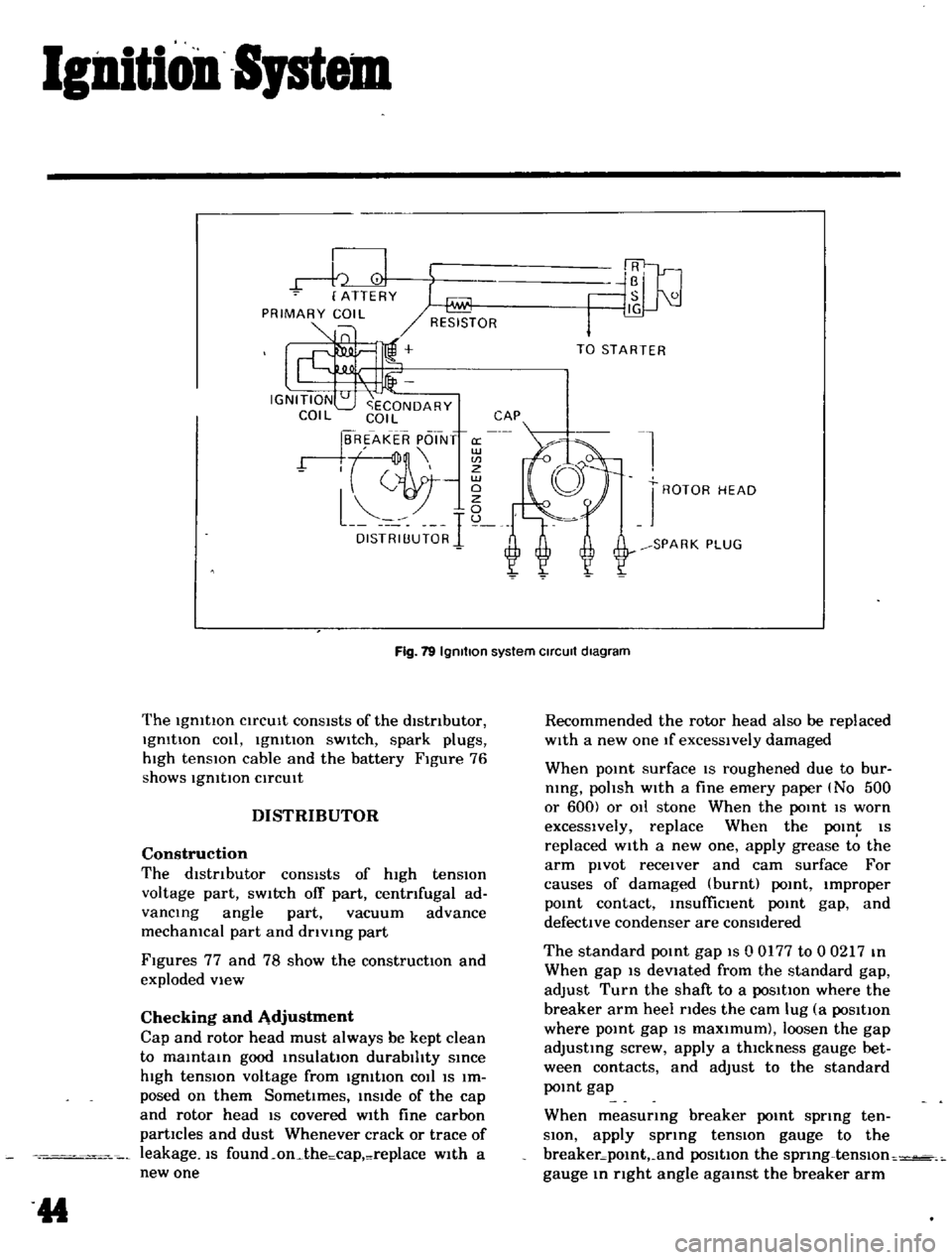
Fig
19
Igmtlon
system
Circuit
diagram
The
IgmtlOn
CirCUIt
conSIsts
of
the
distributor
IgmtIon
cOli
IgmtIon
sWitch
spark
plugs
hIgh
tensIOn
cable
and
the
battery
Figure
76
shows
IgmtlOn
CirCUIt
DISTRIBUTOR
Construction
The
dIstributor
consists
of
high
tension
voltage
part
SWitch
off
part
centrifugal
ad
vancing
angle
part
vacuum
advance
mechamcal
part
and
drlvmg
part
Figures
77
and
78
show
the
constructIOn
and
exploded
view
Checking
and
Adjustment
Cap
and
rotor
head
must
always
be
kept
clean
to
maintain
good
insulation
durability
since
high
tensIOn
voltage
from
IgmtIon
cOil
IS
Im
posed
on
them
SometImes
inside
of
the
cap
and
rotor
head
IS
covered
wIth
fine
carbon
partIcles
and
dust
Whenever
crack
or
trace
of
leakage
IS
found
on
the
cap
replace
w1th
a
new
one
44
Recommended
the
rotor
head
also
be
replaced
wIth
a
new
one
If
excessively
damaged
When
pomt
surface
IS
roughened
due
to
bur
nlng
polish
with
a
fine
emery
paper
No
500
or
600
or
011
stone
When
the
point
IS
worn
excessively
replace
When
the
POIn
IS
replaced
with
a
new
one
apply
grease
to
the
arm
pivot
receiver
and
cam
surface
For
causes
of
damaged
burnt
point
Improper
pomt
contact
msufficlent
point
gap
and
defective
condenser
are
conSidered
The
standard
pomt
gap
IS
0
0177
to
0
0217
m
When
gap
IS
devIated
from
the
standard
gap
adjust
Turn
the
shaft
to
a
posItIon
where
the
breaker
arm
heel
rides
the
cam
lug
a
posItIon
where
pomt
gap
IS
maxImum
loosen
the
gap
adjusting
screw
apply
a
thIckness
gauge
bet
ween
contacts
and
adjust
to
the
standard
pomt
gap
When
measurmg
breaker
pomt
spring
ten
SIOn
apply
sprmg
tensIOn
gauge
to
the
breaker
pomt
and
posItIon
the
sprmg
tenslOn
gauge
m
right
angle
agamst
the
breaker
arm
Page 64 of 136

r
Brakes
Moreover
In
order
to
prevent
brake
squeahng
a
shIm
IS
Inserted
behind
the
pad
BRAKE
PAD
Replacement
Jack
up
front
UnIt
of
the
vehicle
and
remove
the
front
wheel
Remove
clip
from
the
retaining
pin
and
sup
porting
the
brake
pad
remove
the
retaining
pin
and
COil
spring
Unhook
the
hanger
spring
and
Withdraw
the
brake
pad
and
shim
With
a
pair
of
phers
Note
When
the
brake
pad
IS
removed
do
not
depress
the
brake
pedal
or
otherWise
the
piston
will
come
out
Inspection
Clearance
between
the
brake
pad
and
rotor
IS
adjusted
automatically
Check
the
brake
pad
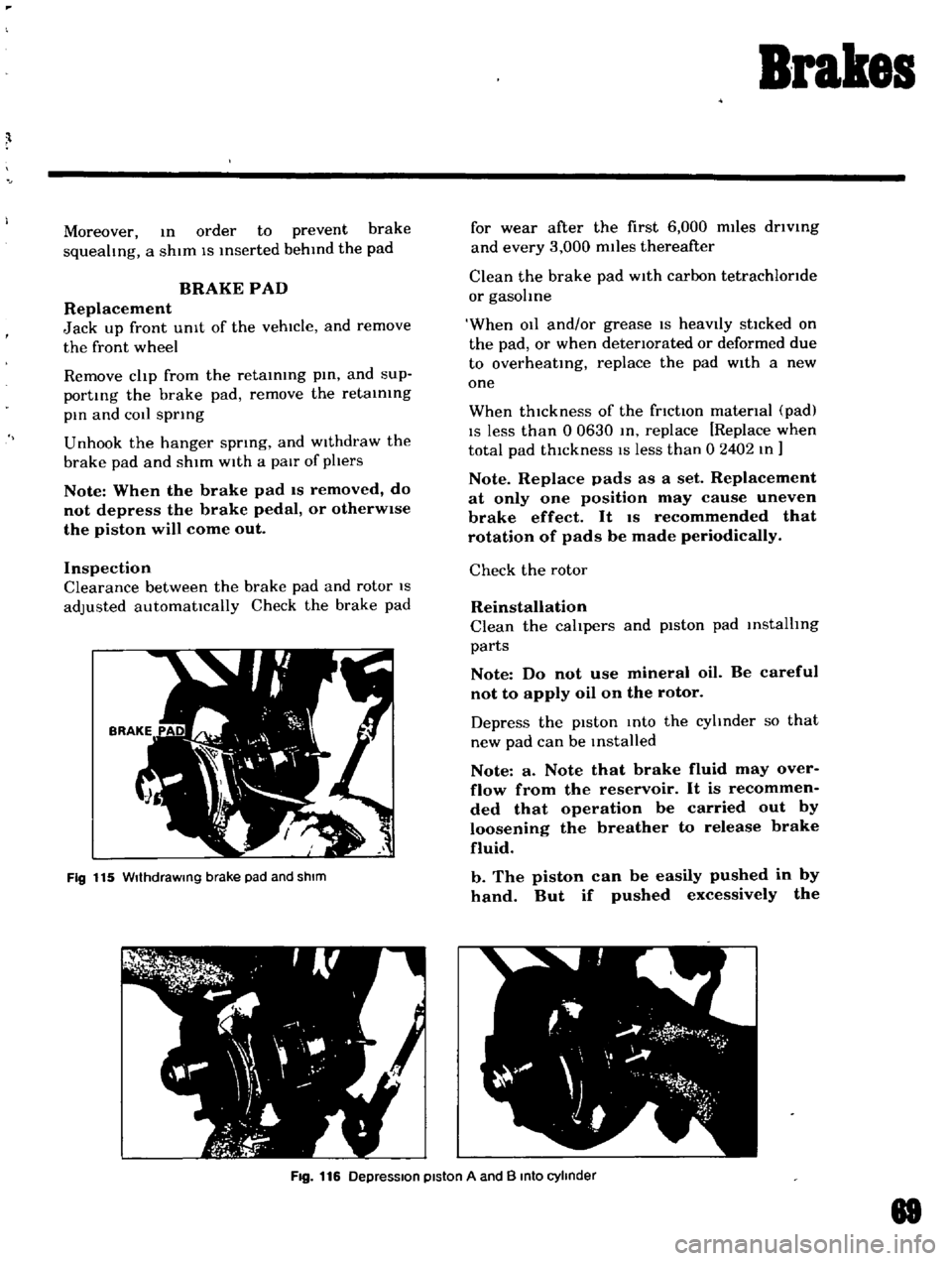
Fig
115
WIthdraWing
brake
pad
and
shIm
for
wear
after
the
first
6
000
miles
driVing
and
every
3
000
miles
thereafter
Clean
the
brake
pad
With
carbon
tetrachloride
or
gasohne
When
011
and
or
grease
IS
heavIly
stlcked
on
the
pad
or
when
deteriorated
or
deformed
due
to
overheating
replace
the
pad
With
a
new
one
When
thickness
of
the
friction
material
pad
IS
less
than
0
0630
In
replace
Replace
when
total
pad
thIckness
IS
less
than
0
2402
In
Note
Replace
pads
as
a
set
Replacement
at
only
one
position
may
cause
uneven
brake
effect
It
IS
recommended
that
rotation
of
pads
be
made
periodically
Check
the
rotor
Reinstallation
Clean
the
calipers
and
piston
pad
installing
parts
Note
Do
not
use
mineral
oil
Be
careful
not
to
apply
oil
on
the
rotor
Depress
the
pIston
Into
the
cyhnder
so
that
new
pad
can
be
Installed
Note
a
Note
that
brake
fluid
may
over
flow
from
the
reservoir
It
is
recommen
ded
that
operation
be
carried
out
by
loosening
the
breather
to
release
brake
fluid
b
The
piston
can
be
easily
pushed
in
by
hand
But
if
pushed
excessively
the
Fig
116
DepreSSion
piston
A
and
B
Into
cylinder
88
Page 93 of 136

Clutch
Pedal
lever
bush
Fulcrum
pedal
pIn
etc
Remstallation
Reinstall
the
clutch
pedal
In
reverse
sequence
of
removal
Adjustment
Adjust
pedal
pad
heIght
to
565
In
Without
stopper
The
adjustment
IS
made
by
selectmg
and
applYIng
shlm
s
haVing
adequate
thIckness
Be
Ule
to
use
shIms
haVIng
same
thIckness
for
both
upper
and
lower
Next
adjust
the
pedal
stopper
properly
so
that
the
pedal
pad
height
IS
557
In
and
secure
the
pOSitIOn
WIth
lock
nut
Note
Make
sure
that
chaSSIS
grease
has
been
applied
to
the
CG
marked
portions
two
places
Grease
if
reqUired
CLUTCH
MASTER
CYLINDER
Removal
DIsconnect
the
push
rod
from
the
cleVIS
DIsconnect
the
clutch
lIne
from
the
master
cylinder
and
draIn
flUid
Remove
the
ecunng
bolts
and
remove
the
master
cyhnder
assembly
from
the
vehIcle
DIsassembly
Remove
the
filler
cap
and
draIn
flUId
Pull
back
the
dust
cover
and
remove
the
snap
rIng
The
stopper
push
rod
pIston
assembly
pnmary
cup
and
return
sptlng
assembly
can
be
removed
Inspection
Thoroughly
clean
all
parts
With
brake
flUId
before
InspectIOn
Check
the
cyhnder
and
piston
for
uneven
wear
or
damage
Replace
If
required
When
clearance
between
the
cylinder
and
pIston
IS
more
than
O
0059
In
replace
the
cyhnder
102
Replace
the
pIston
cup
pnmanly
whenever
the
master
cyhnder
IS
dIsassembled
It
must
also
be
replaced
when
wear
or
deformatIOn
due
to
fatIgue
or
damage
IS
found
Check
the
dust
cover
OIl
reservOIr
filler
cap
and
clutch
lIne
for
damage
or
deformatIOn
If
abnormal
condItIOn
IS
found
replace
With
new
one
Reassembly
Reassemble
the
master
cylInder
assembly
In
reverse
sequence
of
dIsassembly
notIng
the
follOWIng
matters
The
pIston
cup
should
be
soaked
In
brake
flUId
before
reassembly
Install
the
pIston
cup
carefully
so
that
It
IS
correctly
faced
Apply
brake
flUId
suffiCIently
to
the
cyhnder
and
pIston
and
assemble
them
Reinstallation
ReInstall
the
master
cyhnder
assembly
In
reverse
sequence
of
removal
and
adjust
as
follows
Adjust
the
pedal
heIght
by
changmg
the
push
rod
length
Bleed
air
out
of
the
hydrauhc
system
BLEEDING
CLUTCH
SYSTEM
Remove
the
bleed
screw
dust
cap
from
the
operatIng
cyhnder
Open
the
bleed
screw
approximately
three
quarters
of
a
turn
Attach
a
tube
Immer
SIng
the
open
end
mto
a
clean
contaIner
which
contaInS
a
small
amount
of
brake
flUId
Fill
the
master
cyhnder
reservOIr
With
the
recommended
flUId
Depress
the
clutch
pedal
qUIckly
while
keepIng
It
down
retighten
the
bleed
screw
and
allow
It
to
return
slowly
Repeat
thiS
pumpIng
actIOn
unttl
the
flUId
entenng
the
contaIner
IS
free
from
air
bubbles
Screw
up
the
bleed
screw
on
a
down
stroke
of
the
pedal
remove
the
bleec
t1
1
nd
rel1lace
the
dust
cap